Table of Contents
Advertisement
Quick Links
Advertisement
Table of Contents

Related Manuals for Shining 3D EXScan H


Summary of Contents for Shining 3D EXScan H
-
Page 2: Table Of Contents
Scanner Component Connect the cable Installation Computer & Operating system requirement OpenGL Get the installation package Install the software Activation Register for Shining 3D User Account Login Activate the device Online activation Offline activation Upgrade Firmware upgrade Software upgrade Interface... - Page 3 White balance Quick calibration Scan Workflow Preparation Preparation for portrait scan Hair Preparation for different object Scan mode White light mode IR mode Project and project group Project group Create project group Open project group Project Project setting Alignment Resolution Texture Alignment Resolution...
- Page 4 Post Processing Mesh Mesh type Mesh optimization Mesh editing Left panel Bottom panel Right panel Measurement Create Features Movement Measurement...
-
Page 5: Overview
Overview... -
Page 6: Welcome
This document is related to your safety, lawful rights and responsibilities. Read it carefully before installing and using the product. SHINING 3D Tech Co., Ltd. (hereinafter referred to as “the Company”) owns complete intellectual property rights for the contents of this document and, without the written consent of the Company, it is not allowed to copy, transmit, publish, reedit, compile or translate any contents of this document for any purpose or in any form. -
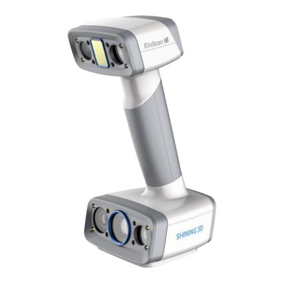
Page 7: Device
Device Please read carefully before the first time of using EinScan H2 (hereinafter referred to as the "Scanner"). Appearance Scanner... - Page 8 Appearance Description Working distance indicator Zoom in / Zoom out Brighter / Darker Preview / Scan / Pause USB port Power port...
-
Page 9: Component
Component... -
Page 10: Connect The Cable
Connect the cable Warning Make sure you are using the correct power adapter. Steps 1. Plug USB and DC IN into the bottom of Scanner. - Page 11 2. Plug the power cable into the connection cable. 3. Power on and the LED indicator should show white.
- Page 12 4. Plug the other side of connection cable into the USB port of computer. Now you can see our device in your Device Manager.
-
Page 14: Installation
Installation To use the scanner, you need to install the EXScan software first (hereinafter referred to as the "software"). Computer & Operating system requirement Recommended computer: Component Model Intel® Core™ i7-8700 or above Graphics card NVIDIA GTX 3060 or above Graphics memory 4GB or above 32GB or above... -
Page 15: Opengl
OpenGL To use the scanner, you need a graphics card (integrated or discrete) which can support OpenGL4.3 or above. OpenGL Extensions Viewer (https://realtech-vr.com/home/glview) to check the OpenGL version, if it's lower than 4.3, please update the graphics card driver and check again. If it's still lower than 4.3, it means that the graphic card CAN NOT support the scanner. -
Page 16: Gpu
Highly recommend to use a NVIDIA discrete graphics card for the scanner. The NVIDIA discrete graphics card should support CUDA10.2 or above. Use NVIDIA Control Panel to get the CUDA version with follow steps. Launch NVIDIA Control Panel Go to Help>>System information>>Components. -
Page 17: Get The Installation Package
Use a discrete graphics card on desktop Connect your monitor to the port of discrete graphics card on the back of your computer, OS will use the discrete graphics card automatically. Use a discrete graphics card on laptop Launch NVIDIA Control Panel on your laptop. In 3D Settings -->... -
Page 18: Install The Software
Please visit the following website to get the installation package: https://www.einscan.com/support/download (https://www.einscan.com/support/download/) Install the software Please follow the installation wizard to install the software. Note ● Administrator rights are required for the software installation. The initial installation environment may take a long time, please wait patiently. -
Page 19: Activation
Activation When using the scanner for the first time, please register an account to activate the device. Register for Shining 3D User Account Click Register and fill in the account information in the registration pop-up. -
Page 20: Login
Fill in correct user information for better service. Login Log in Shining 3D User Account from the pop-up window when launching the software. If your computer failed to connect to the network: ● Check the network connection and click Refresh to reconnect to the network. It will jump back to the login interface after successfully connecting to the network. -
Page 21: Offline Activation
Offline activation You need another computer which is connected to Internet to help you finish the offline activation. 1. Connect scanner to the computer with no network, export C2V file. 2. Copy the C2V file to the other computer connected to Internet. 3. - Page 22 4. Copy the V2C file to the computer with no network, import the file into the software.
- Page 23 Note If you fail to activate the device in neither way, please contact your supplier or our support team (https://support.einscan.com/)
-
Page 24: Upgrade
Upgrade When new software is released, you will get prompted when launching the software. If the firmware in the software is newer than that in the scanner, you will get prompted too. Firmware upgrade The firmware is running on the scanner, it will be upgraded for better performance, stability or bug fixing. Warning Make sure that the device is powered on during the upgrade;... - Page 25 Click Download Now will download the new installation package in the background, you can continue using the software. Please do not close the software before the download has finished. Once it finished, the following prompt will show. Click Yes to start the installation of the new version.
-
Page 26: Interface
Interface Navigation bar Navigation Description Device Displays the device status: online / offline Calibration Click to start calibration. Scan Mode Select different scan mode: white light mode / IR mode Scan Into scan process. Post Processing Into post processing after generating the point cloud, includes mesh mesh editing. -
Page 27: Settings And Feedback
Settings and feedback Social Function Description Official Open the official website (https://www.einscan.com) of Shining 3D to learn about the company’s Website products and information. Facebook Enter Shining 3D’s facebook (https://www.facebook.com/groups/einscan) to view product introduction and other operations. Support Enter Shining 3D’s support platform (https://support.einscan.com/en/support/home) -
Page 28: Help
Help Function Description Calibration Checked by default. It will display guide in calibration. Guide User Manual Open a browser to show user manual. Teamviewer The quick access to remote assistance. Send the ID and password in the pop-up window to the technical supporters for remote assistance. -
Page 29: Other Components
Other components Component Description Camera Window This is the camera window in scan process. Show one by default, you can open other camera windows through Right-click menu. Project Group Here you can manage your project group, for more detail please refer Project and project group. - Page 30 Component Description Working distance indicator Indicate working distance between the scanner and the object. Green: proper Red: too close Blue: too far Edit Please refer to Data edit. Sidebar Please refer to Scan function.
-
Page 31: Quick Guide
Quick guide 1. Select scan mode. 2. Create a project group, setup project settings. 3. Set scan parameters while preview Scan generate point clouds. 5. Mesh. Save the scan data. -
Page 32: Calibration
Calibration With calibration, the scanner parameters are recalculated, which not only ensures the accuracy of the scanner, but also improve the quality of scanning. Note Calibration is required under the following conditions: When the scanner is used for the first time. The scanner was severely shaken or shocked, such as shocked during transportation. - Page 33 2. Press the scan button on the scanner to start calibration. 3. Move the device slowly and adjust the distance between the scanner and the calibration board according to the height indicating box. 4. Keep moving until all height boxes turn green. 5.
- Page 34 Note If the calibration fails, please try it again from step1. If you cannot get the pass result anyway, please contact your supplier or our support team (https://support.einscan.com/) White balance 1. Place the calibration board on a horizontal flat surface with its back site (white) lying towards up. 2.
- Page 35 After finishing the white balance calibration, click Next on the following pop-up for entering the scan mode. Note Do not do white balance or scan under strong light, it may cause color deviation. If white balance fails, please try it again. If you cannot get the pass result anyway, please contact your supplier or our support team (https://support.einscan.com/)
- Page 36 1. Place the calibration board onto the holder, with its front site (black with markers) towards the scanner. 2. Place the scanner as shown in the software, then press the scan button on the scanner to start calibration. 3. Move the device slowly and adjust the distance between the scanner and the calibration board according to the height indicating box.
- Page 37 Scan...
- Page 38 Workflow Below is the workflow of the scanner. There are two different workflows: Basic workflow, Global marker workflow. The basic workflow can fulfill most of your needs, if you want higher accuracy, you can use global marker workflow.
- Page 39 Basic Workflow Select scan White light mode 选择扫描模式 选择扫描模式 选择扫描模式 选择扫描模式 mode IR mode Create new 创建多工程 创建多工程 创建多工程 创建多工程 创建多工程 创建多工程 project group IR mode White light mode Select scan object Alignment Project settings 工程设置 工程设置 工程设置 工程设置 工程设置 工程设置...
- Page 40 Global Marker Workflow Select scan White light mode 选择扫描模式 选择扫描模式 选择扫描模式 选择扫描模式 mode IR mode Create new 创建多工程 创建多工程 创建多工程 创建多工程 创建多工程 创建多工程 project group White light mode / IR mode Global marker alignment Project settings 工程设置 工程设置 工程设置 工程设置 工程设置...
- Page 41 Preparation Object has good geometry or texture features will get scanned easily and fast with good quality. If not, you need to do some preparation before scanning. Note Not recommend to scan following objects: Moving or vibrating objects, which cause the shape of object changed during scanning process. Soft material object.
- Page 42 Preparation for different object Object Preparation Notes while scanning Transparent, shiny, reflective surface Use washable or vanishing scanning Scan as normal objects spray Objects with less features or repetitive - Place markers on the object. - Select hybrid alignment. features - Mark/draw on the surface to add - Select texture alignment features...
- Page 43 Scan mode There are two scan modes: White light mode and IR mode. White light mode Use white light source for scanning, with higher scan data quality and accuracy, suitable for scanning non- reflective, non-black material objects.
- Page 44 IR mode Use the infrared light for scanning, the data quality and scan accuracy are lower than the white light mode, it is often used to scan people and black or slightly reflective materials.
- Page 45 Project and project group Project group To start scanning, you need to create / open a project group. Project group is the standard file structure of the software, it contains one project or more. Each project contains the scan data of its own. Project Group Scenario Description...
- Page 46 Note Current project group will be saved automatically. Two ways to open a project group: 1. Before scanning, select scan mode, then click open project group in prompt. 2. In scan window, click project group in side bar, then click open project group in prompt. In the prompt window, select the project group file and then open.
- Page 47 icon function instruction note & warning Create new Two ways to create a project: Only can create project when project 1. A project will be created scanner connected. automatically when you create a project group. 2. In scan window, click to create a new project.
- Page 48 Project setting White light mode Alignment Alignment Instruction Feature Uses object geometric features for auto aligning during scanning. Rich features on the object are required for this mode. Texture Uses objects surface texture to align the scans. Compared with feature alignment, texture alignment takes longer and consumes more memory.
- Page 49 Note Texture switch cannot be changed once the project group been created. IR mode The scanner support two scan targets: Portrait scan, Object scan. You need to choose scan target when you create the project. With different scan target, the settings below will be different.
- Page 50 Note FEATURE ALIGNMENT uses object geometric features for auto aligning during scanning. Rich features on the object are required for this mode. TEXTURE ALIGNMENT uses objects surface texture to align the scans. Compared with feature alignment, texture alignment takes longer and consumes more memory. It is recommended to use the texture alignment only in cases where the object's geometrical features are insufficient.
- Page 51 Note Texture switch cannot be changed once the project group been created.
- Page 52 Scanning...
- Page 53 Scan setting Following parameters can be set when scanning. Brightness Adjust the brightness for different material / color of the object to get better scan data. Too high Proper Too low Working distance Use short working distance to get more detail, but need more time to scan the whole object. Use long working distance to get large FOV, scan time will be shorter, but will lose some detail of the data.
- Page 54 Other function Function Value Instruction Data Quality ON/OFF To indicate the data quality of your scan, help you to get better scan data. Indicator - Only available before generating point cloud. Texture LED ON/OFF Please turn on the LED light when there is not enough light for better Light texture scanning ( This function is enabled by default).
- Page 55 Scanning Preview / Scan / Pause You can always switch in these 3 status with the trigger on the scanner, or click the button in the software. The basic switch order is: Preview -- Scan -- Pause Function Icon Instruction Preview In this mode, only show data for preview, but not record the data, you can modify scan parameters...
- Page 56 Preview Caution When scanning the recessed areas of an object, please hold the scanner directly towards the area to be scanned. Generate point clouds When you finish the scan, you can Generate Point Clouds or Optimize and Generate Point Clouds .
- Page 57 1. To generate point cloud directly without any optimization, will be fast and less memory been used; Only available in Object Scan. 2. Optimize then generate point cloud, suggest choosing this option when you have higher accuracy requirement or when there is layering problem caused by accumulated aligning errors during scanning.
- Page 58 Scan data edit We provide functions to edit the scan data when you pause scanning or after you generate point cloud.
- Page 59 Icon Function Instruction Multi View There are 6 different view angles for you to choose. Create Cutting Create a plane to do quick cut, check below for detail. Plane Rectangular Click and hold LMB to drag to select / deselect an area of the data. Polygon Click LMB one-by-one to select / deselect an area of the data.
- Page 60 Icon Function Instruction Cancel Undo all edit, and exit edit mode. Apply Click the button or space bar to apply the edit, and exit edit mode. Note press Shift + LMB to select the area. press Ctrl + LMB to deselect the area. Cutting plane Cutting plane is very useful when a base needs to be removed during scanning.
- Page 61 Set cutting plane Method Instruction Rotation axis Cutting plane can be rotated around the axis by dragging the small ball. Move cutting Move the cutting plane by operating the active bar, editing the text box or dragging the arrow. plane Delete Click this option, data in the reverse direction will be shown in red.
- Page 62 Scan functions Before or after scanning, you can access the other scan functions through the sidebar function buttons. Icon Function Instruction Project Group Create / open a project group. About project group, please refer to Project Group. Clean Data Clean the current point cloud data to redo scan. Align Align the data as you need, please refer to Align.
- Page 63 Align point cloud This is how you align multiple projects in one project group. Click on the right side of the interface to enter the project alignment interface. Align Instruction Note Mode Choose Feature Alignment and Regular shaped objects (circular objects and square click Apply, alignment will be objects included) or small sized objects are not suitable performed automatically.
- Page 64 Post Processing...
- Page 65 Mesh Meshing is to convert the point cloud into a triangular mesh surface. The data after mesh can be directly used for rendering, measurement or printing. Mesh type Icon Function Instruction Unwatertight Unclosed model stays the way it is scanned. Processing time is quicker than Watertight.
- Page 66 Mesh optimization Optimization Instruction Note Filter Optimize the data and improve the - None: No optimization clarity of the data. The higher the level, - Low: Optimizes data slightly and preserves the less the small details . data characteristics - Med: Reduce the noise on the surface of the scan data - High: Reduce the noise on the surface of the scan data and sharpen it powerfully.
- Page 67 Optimization Instruction Note Remove spike Remove spike-like data on the image edge. Marker hole fill Fill in the surface of the object that is not scanned to the pasting marker. Click Apply to confirm the settings and start meshing, you can click to restore or click Confirm to confirm the mesh result.
- Page 68 Mesh editing Left panel Click + to open each function.
- Page 69 Function Instruction Note Brightness and Contrast can be Confirm to apply, Cancel to restore Texture adjusted. Simplification After simplification, the polygon High level may cause detail loss. Set the ratio from numbers, file size and detail of data 1 to 100, the default is 0. will be reduced universally.
- Page 70 Function Instruction Note Cutting Plane Define a plane by drawing a straight line. Delete the selection Tool and close the mesh at the intersection. Use the cutting plane to align the mesh to the CSYS. Mirror Mirror the mesh through a plane defined by a straight line. After mirroring, texture remapping cannot be performed.
- Page 71 Right panel Icon Function Instruction Open file Open a file (STL, OBJ, PLY) for post processing. Save Data Save scan data. Sketchfab Use your Sketchfab (https://sketchfab.com) account to share the model. Upload Third-party Save the data and open with third-party software. software Texture After the post-processing, hole filling on texture scanned data will affect the...
- Page 72 Measurement...
- Page 73 You can measure on the model you just scanned, or you can open a model file to do the measurement. Click to select the file to be measured; or directly drag the file (STL, OBJ, PLY) to the measurement interface. Create Features Click to display the menu of creating features.
- Page 74 Point Creation Method Description Note Selected Points ● Click on the data to select a point. ● Click Create to create a point. Line-Plane ● Click on the created line, or select it on the Line and Plane should be Intersection dropdown.
- Page 75 Plane Creation Description Note Method 3 Points Fit ● The plane is generated by 3 points not co-linear. The 3 points can't be on the ● Click on the data to select one point or click on a previous same line. created feature point.
- Page 76 Movement Use this mode to modify the alignment of the data to the global coordinate. This action is useful for post processing or reverse engineering. Caution ● The shape and accuracy of the model will not be changed by the movement. ●...
- Page 77 Exact Movement Click "Move to" to align the model center with the input coordinates, and the axis direction is adjusted to match the input rotation angle. The coordinate system displayed on the interface is the global coordinate system, in which the direction of the red line is the positive direction of X-axis, green is the positive direction of Y-axis and blue is the positive direction of Z- axis.
- Page 78 Select a feature line in the drop-down menu of the line, and select an axis in the drop-down menu of the line. The arrow of the line indicates the positive direction of the line, and the direction of the selected axis will be consistent with the direction of the projection of the line on the selected plane.
- Page 79 Measurement Click to enter the measurement interface and the menu is displayed. Click it again to exit. Measurement Description Steps Distance Calculate the distance between two Click on the surface of the model to pick two points on the surface of the model. points, the calculation will be done automatically.
Need help?
Do you have a question about the EXScan H and is the answer not in the manual?
Questions and answers