Table of Contents
Advertisement
Quick Links
Advertisement
Table of Contents

Subscribe to Our Youtube Channel
Related Manuals for Shining 3D EinScan H


Summary of Contents for Shining 3D EinScan H
-
Page 2: Safety Instructions
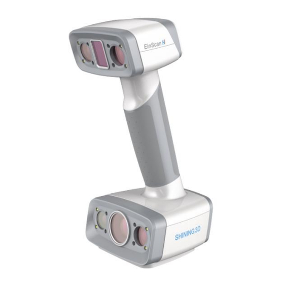
This document is related to your safety, lawful rights and responsibilities. Read it carefully before installing and using the product. SHINING 3D Tech Co., Ltd. (hereinafter referred to as “the Company”) owns complete intellectual property rights for the contents of this document and, without the written consent of the Company, it is not allowed to copy, transmit, publish, reedit, compile or translate any contents of this document for any purpose or in any form. - Page 3 In the event of any ambiguity and/or any advice on the contents of the document, contact us by the contact For more information, please visit our support website: support.einscan.com Please read carefully before the first time of using EinScan H (hereinafter referred to as the "Scanner"). Appearance Scanner...
- Page 4 Appearance Description Working distance indicator Zoom in / Zoom out Brighter / Darker Preview / Scan / Pause USB port Power port Component...
-
Page 5: Connect The Cable
Connect the cable Warning Make sure you are using the correct power adapter. Steps 1. Plug USB and DC IN into the bottom of Scanner. - Page 6 2. Plug the power cable into the connection cable. 3. Power on and the LED indicator should show white.
- Page 7 4. Plug the other side of connection cable into the USB port of computer. Now you can see our device in your Device Manager. To use the scanner, you need to install the EXScan software first (hereinafter referred to as the "software").
- Page 8 Computer & Operating system requirement Recommended computer: Component Model Intel® Core™ i7-8700 or above Graphics card NVIDIA GTX 1080 or above Graphics memory 4GB or above 32GB or above 3.0 or above Recommended operating system: Windows 10, Windows 11 (both 64-bit only) Improper computer configuration or hardware issues will cause CPU performance degradation and affect the user experience, it is recommended to use the CPU-Z tool to check CPU performance before starting scanning.
- Page 9 OpenGL To use the scanner, you need a graphics card (integrated or discrete) which can support OpenGL4.3 or above. OpenGL Extensions Viewer to check the OpenGL version, if it's lower than 4.3, please update the graphics card driver and check again. If it's still lower than 4.3, it means that the graphic card CAN NOT support the scanner.
- Page 10 Highly recommend to use a NVIDIA discrete graphics card for the scanner. The NVIDIA discrete graphics card should support CUDA10.2 or above. Use NVIDIA Control Panel to get the CUDA version with follow steps. Launch NVIDIA Control Panel Go to Help>>System information>>Components.
- Page 11 Use a discrete graphics card on desktop Connect your monitor to the port of discrete graphics card on the back of your computer, OS will use the discrete graphics card automatically. Use a discrete graphics card on laptop Launch NVIDIA Control Panel on your laptop. In 3D Settings -->...
-
Page 12: Install The Software
You need a Shining 3D User Account before activating the device. Register for Shining 3D User Account For new user, you need to register a Shining 3D User Account first, click Register in the pop-up window when launching the software, or click Sign Up in our Shining 3D User Account website: https://passport.shining3d.com/... - Page 13 Note You need to enter valid email or phone number to get verify code for registration. Please enter correct user information for better service. Please read and then check Privacy Policy and Terms of use.
-
Page 14: Activate The Device
Log in Shining 3D User Account Log in Shining 3D User Account from the pop-up window when launching the software. Activate the device Online activation If the computer is connected to the Internet, the activation will be processed automatically after you login Shining 3D User Account. - Page 15 1. Connect scanner to the computer with no network, export C2V file. 2. Copy the C2V file to the other computer connected to Internet. 3. On the computer with network, login https://passport.shining3d.com/, upload your C2V file in offline activation page and complete the information of activation, you can then download the V2C file.
- Page 16 4. Copy the V2C file to the computer with no network, import the file into the software.
-
Page 17: Firmware Upgrade
Note If you fail to activate the device in neither way, please contact your supplier or our support team. When new software is released, you will get prompted when launching the software. If the firmware in the software is newer than that in the scanner, you will get prompted too. Firmware upgrade The firmware is running on the scanner, it will be upgraded for better performance, stability or bug fixing. - Page 18 Warning The software will be closed during upgrading, please save your projects properly before upgrading. It is highly recommended to use the latest version of software. If not, a reminder will pop up immediately when you launch the software. Click Download Now will download the new installation package in the background, you can continue using the software.
-
Page 19: Navigation Bar
Navigation bar Navigation Description Device Displays the device status: online / offline Calibration Click to start calibration. Scan Mode Select different scan mode: white light mode / IR mode Scan Into scan process. Post Into post processing after generating the point cloud, includes mesh Processing mesh... - Page 20 Social Function Description Official Open the official website of Shining 3D to learn about the company’s Website products and information. Facebook Enter Shining 3D’s Facebook to view product introduction and other operations. Support Enter Shining 3D’s support platform to view product introduction and Platform other operations.
- Page 21 Help Function Description Calibration Checked by default, will display guide in calibration. guide User Open a browser to show user manual. Manual Teamviewer The quick access to remote assistance. Send the ID and password in the pop-up window to the technical supporters for remote assistance. Other component Component Description...
- Page 22 Project Information In this area, you can check the project information and computer information. Working distance indicato Indicate working distance between the scanner and the object. Green: proper Red: too close Blue: too far Edit Please refer to Data edit. Sidebar Please refer to Scan...
-
Page 23: Standard Calibration
Note Calibration is required under the following conditions: When the scanner is used for the first time. The scanner was severely shaken or shocked, such as shocked during transportation. Severe accuracy reduction, such as frequent errors in alignment or unrecognized markers. - Page 24 2. Press the scan button on the scanner to start calibration. 3. Move the device slowly and adjust the distance between the scanner and the calibration board according to the height indicating box. 4. Keep moving until all height boxes turn green. 5.
-
Page 25: White Balance
Note If the calibration fails, please try it again from step1. If you cannot get the pass result anyway, please contact your supplier or our support team. White balance 1. Place the calibration board on a horizontal flat surface with its back site (white) lying towards up. - Page 26 After finishing the white balance calibration, click Next on the following pop-up for entering the scan mode. Note Do not do white balance or scan under strong light, it may cause color deviation. If white balance fails, please try it again. If you cannot get the pass result anyway, please contact your supplier or our support team.
-
Page 27: Quick Calibration
Quick calibration Quick calibration can be used for re-calibration when accuracy reduction or misalignment during scanning. Only one position should be done during quick calibration. 1. Place the calibration board onto the holder, with its front site (black with markers) towards the scanner. - Page 28 Below is the workflow of the scanner. There are two different workflows: Basic workflow, Global marker workflow. The basic workflow can fulfill most of your needs, if you want higher accuracy, you can use global marker workflow. Basic Workflow Select scan White light mode 选择扫描模式...
- Page 29 Create new 创建多工程 创建多工程 创建多工程 创建多工程 创建多工程 创建多工程 project group White light mode / IR mode Global marker alignment 工程设置 工程设置 工程设置 工程设置 工程设置 工程设置 Project settings Resolution Texture Import global marker Scan global 导入框架点 扫描框架点文件 扫描框架点文件 扫描框架点文件 扫描框架点文件 扫描框架点文件 扫描框架点文件...
- Page 30 Note Not recommend to scan following objects: Moving or vibrating objects, which cause the shape of object changed during scanning process. Soft material object. Lattice structures with many small deep holes. Preparation for portrait scan Hair Bad sample Good sample...
- Page 31 Preparation for different object Object Preparation Notes while scanning Transparent, shiny, reflective Use washable or vanishing Scan as normal surface objects scanning spray Objects with less features or - Place markers on the - Select hybrid repetitive features object. alignment. - Mark/draw on the surface - Select texture to add features...
- Page 32 Project and project group Project group To start scanning, you need to create / open a project group. Project group is the standard file structure of the software, it contains one project or more. Each project contains the scan data of its own. Scenario Project group Instruction...
- Page 33 Create project group Two ways to create a project group: 1. Before scanning, select scan mode, then click new project group in prompt. 2. In scan window, click project group in side bar, then click new project group in prompt. In the prompt window, name the project group and new to the path you choose, all the scan data will be saved to the folder with the name you just set.
- Page 34 icon function instruction note & warning Create new Two ways to create a Only can create project project: project when scanner 1. A project will be created connected. automatically when you create a project group. 2. In scan window, click to create a new project.
- Page 35 White light mode Alignment Alignment Instruction Feature uses object geometric features for auto aligning during scanning. Rich features on the object are required for this mode. Texture uses objects surface texture to align the scans. Global uses global markers file to help align the scans. You may add an existed Markers global markers file or scan one.
- Page 36 IR mode The scanner support two scan targets: Portrait scan, Object scan. You need to choose scan target when you create the project. With different scan target, the settings below will be different. Note You can select Medium object or Large object under object scan. Medium object: size between 100mm X 100mm X 100mm and 300mm X 300mm X 300mm.
- Page 37 FEATURE ALIGNMENT uses object geometric features for auto aligning during scanning. Rich features on the object are required for this mode. TEXTURE ALIGNMENT uses objects surface texture to align the scans. Texture Scan is required to select if you want to use texture align. GLOBAL MARKERS ALIGNMENT uses global markers file to help align the scans.
-
Page 38: Working Distance
Note Texture switch cannot be changed once the project group been created. Following parameters can be set when scanning. Brightness Adjust the brightness for different material / color of the object to get better scan data. Too high Proper Too low Working distance Use short working distance to get more detail, but need more time to scan the whole object. -
Page 39: Other Function
Other function Function Value Instruction Data ON/OFF To indicate the data quality of your scan, help you to get Quality better scan data. Indicator - Only available before generating point cloud. Texture ON/OFF Please turn on the LED light when there is not enough LED Light light for better texture scanning ( This function is enabled by default). - Page 40 Preview Generate point cloud When you finish the scan, you can Generate Point Cloud or Optimize and Generate Point Cloud . You may want to edit the data later. Note The time it takes to generate point cloud depends on the data size of your project and the hardware configuration of your PC.
- Page 41 Icon Function Instruction Multi View There are 6 different view angles for you to choose. Create Create a plane to do quick cut, check below for detail. Cutting Plane Rectangular Click and hold LMB to drag to select / deselect an area of the data.
- Page 42 Delete Click the button or “DELETE” on the keyboard to delete selected data. Undo Click the button to undo the most recently operations. Cancel Undo all edit, and exit edit mode. Apply Click the button or space bar to apply the edit, and exit edit mode.
- Page 43 Method Instruction Fitting Press Shift + LMB to select data, then click the button “Generate plane”. Point Cloud The cutting plane will be created by point cloud fitting. The direction of the plane will be calculated by the software according to the direction of point cloud.
- Page 44 Icon Function Instruction Project Group Create / open a project group. About project group, please refer to Project Group. Clean Data Clean the current point cloud data to redo scan. Align Align the data as you need, please refer to Align. Save Data Save scan data.
- Page 45 Align Instruction Note Mode Choose Feature Regular shaped objects (circular objects and Alignment and click square objects included) or small sized Apply, alignment will objects are not suitable for this mode. be performed automatically. Manually choose at - The chosen points should NOT in a line. least 3 common - Manual alignment is a supplement to feature points in the fixed...
- Page 46 Mesh type Icon Function Instruction Unwatertight Unclosed model stays the way it is scanned. Processing time is quicker than Watertight. Half Some of the holes will be filled automatically. watertight Holes with a diameter less than or equal to the resolution*5 will be filled.
-
Page 47: Left Panel
numbers, file size and detail will be selected by default. of data while meshing. - Resolution > 0.5mm, simplification will be deselected by default. Max triangles Set max plate number to get mesh model’s triangle plate number is within configured plate number. - Page 48 Simplification After simplification, the High level may cause detail loss. Set the polygon numbers, file ratio from 1 to 100, the default is 0. size and detail of data will be reduced universally. Mesh Mesh optimization can Optimization optimize the quality of the data by adding more triangles to curvature regions.
-
Page 49: Bottom Panel
Flip Normal To redefine the front Texture mapping will be unavailable after direction of the scanned flip Normal data in reversal design. Cutting Define a plane by Plane Tool drawing a straight line. Delete the selection and close the mesh at the intersection. -
Page 50: Right Panel
Right panel Icon Function Instruction Open file Open a file (STL, OBJ, PLY) for post processing. Save Data Save scan data. Sketchfab Use your Sketchfab account to share the model. Upload Third-party Save the data and open with third-party software. software Texture After the post-processing, hole filling on texture scanned... - Page 51 Point Creation Requirement Description Method Selected Click on the data to select a point. Points Click create to create a point. Line-Plane Line and Plane should Click on the created line, or select it on the Interface be created in advanced drop-down.
- Page 52 Plane Creation Requirement Description Method 3 Points Fit The plane is generated by 3 points not co-linear. Click on the data to select one point or click on a previous created feature point. In the Choice list select one of the points to re- select it.
- Page 53 Movement Description Steps method Exact - Offset: adjust the object 1. Enter the setting value then click Offset Movement data center coordinates in or Rotate. X, Y, Z axis. 2. Repeat step 1 until it meets your needs. - Rotation: adjust the 3.
- Page 54 Measurement Description Steps Distance Calculates the distance Click on the surface of the model to between two points on the pick two points, the calculation will be surface of the model. done automatically. Total is the 3D distance, X, Y and Z are the projection of the segment to the respective planes.
Need help?
Do you have a question about the EinScan H and is the answer not in the manual?
Questions and answers