Table of Contents
Advertisement
Advertisement
Table of Contents

Related Manuals for Shining 3D Einstar


Summary of Contents for Shining 3D Einstar
-
Page 2: Safety Instructions
Disclaimer Safety instructions Signal Meaning Additional information for particular situation. Improper actions or conditions that may damage the product, and consequently void your warranty or service contract or lose the customer data or system data. The safety instructions that you must precisely follow to avoid injury. Failure to observe can cause damages to your product, or result in personal injuries. -
Page 3: About This Document
This document is related to your safety, lawful rights and responsibilities. Read it carefully before installing and using the product. SHINING 3D Tech Co., Ltd. (hereinafter referred to as “the Company”) owns complete intellectual property rights for the contents of this document and, without the written consent of the Company, it is not allowed to copy, transmit, publish, reedit, compile or translate any contents of this document for any purpose or in any form. - Page 4 In the event of any ambiguity and/or any advice on the contents of the document, contact us by the contact For more information, please visit our support website: support.einstar.com Device Please read carefully before the first time of using Einstar (hereinafter referred to as the "Scanner").
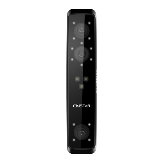
- Page 5 Appearance Scanner Appearance Description Working distance indicator Scanner status indicator Zoom in/Brighter Preview/Scan/Pause Zoom out/Darker...
- Page 6 Note During scan, press scan button twice to enter brightness adjustment, then you can use button 3 and 5. Component...
-
Page 7: Connect The Cable
Components Description wrist strap scanner body USB cable power adapter 12V/5A power cable calibration board markers quick start guide Connect the cable Warning Make sure you are using the correct power adapter (12V/5A). - Page 8 Steps 1. Plug USB cable into the bottom of Scanner, the red dot should be consistent with the front side of the scanner. 2. Plug the power cable into the USB cable. 3. Power on and the LED indicator should show blue.
- Page 9 4. Plug the other side of USB cable into the USB port of computer. Now you can see our device in your Device Manager.
-
Page 10: Install Software
Hold the scanner Put on and tighten the wrist strap. Hold the scanner securely as shown in the picture. Install software To use the scanner, you need to install the EXStar software first (hereinafter referred to as the "software"). Computer & Operating system requirement Recommended computer: Component Model... - Page 11 Improper computer configuration or hardware issues will cause CPU performance degradation and affect the user experience, it is recommended to use the CPU-Z tool to check CPU performance before starting scanning. CPU-Z: https://www.cpuid.com/softwares/cpu-z.html Install and launch CPU-Z, follow the steps in below figure to get a CPU multi thread performance score.
- Page 12 It is highly recommend to use a NVIDIA discrete graphics card for the scanner. The NVIDIA discrete graphics card should support CUDA10.2 or above. Use NVIDIA Control Panel to get the CUDA version with follow steps. Launch NVIDIA Control Panel Go to Help>>System information>>Components.
- Page 13 Use a discrete graphics card on desktop Connect your monitor to the port of discrete graphics card on the back of your computer, OS will use the discrete graphics card automatically. Use a discrete graphics card on laptop Launch NVIDIA Control Panel on your laptop. In 3D Settings -->...
-
Page 14: Install The Software
You need a Shining 3D User Account before activating the device. Register for Shining 3D User Account For new user, you need to register a Shining 3D User Account first, click Register in the pop-up window when launching EXStar, or click Sign Up in our Shining 3D User Account website: https://passport.shining3d.com/... - Page 15 Please read and then check Privacy Policy (Mandatory). Log in Shining 3D User Account Log in Shining 3D User Account from the pop-up window when launching EXStar. If your computer failed to connect to the network: ●Check the network connection and click Refresh to reconnect to the network. It will jump back to the login interface after successfully connecting to the network.
-
Page 16: Online Activation
Online activation If the computer is connected to the Internet, the activation will be processed automatically after you login Shining 3D User Account. Offline activation You need another computer which is connected to Internet to help you finish the offline activation. - Page 17 2.Copy the C2V file to the other computer which is connected to Internet. 3.On the computer with network, login https://passport.shining3d.com/, upload your C2V file in offline activation page, complete the information then click Activate button to go to download page. 4.Copy the V2C file to the computer with no network, import the file into the software.
-
Page 18: Firmware Upgrade
Upgrade When new software is released, you will get prompted when launching the software. If the firmware in the software is newer than that in the scanner, you will get prompted too. Firmware upgrade The firmware is running on the scanner, it will be upgraded for better performance, stability or bug fixing. - Page 19 It is highly recommended to use the latest version of software. If not, a reminder will pop up immediately when you launch the software. Click Download Now will download the new installation package in the background, you can continue using the software. Please do not close the software before the download has finished.
-
Page 20: Navigation Bar
Navigation bar Navigation Description Device Displays the device status: online / offline Calibration Click to start calibration. Scan Into scan process. Post Into post processing after generating the point cloud, includes mesh Processing mesh editing. Measurement Use the software to measure your model. - Page 21 Social Function Description Official Open the official website of Shining 3D to learn about the company’s Website products and information. Facebook Enter Shining 3D’s Facebook to view product introduction and other operations. Support Enter Shining 3D’s support platform to view product introduction and Platform other operations.
- Page 22 Help Function Description Calibration Checked by default, will display video guide in calibration. Guide User Open a browser to show user manual. Manual Teamviewer The quick access to remote assistance. Send the ID and password in the pop-up window to the technical supporters for remote assistance. Other component Component Description...
- Page 23 Project Information In this area, you can check the project information and computer information. Working distance indicato Indicate working distance between the scanner and the object. Green: proper Red: too close Blue: too far Edit Please refer to Data edit. Sidebar Please refer to Scan...
- Page 24 Note Calibration is required under the following conditions: When the scanner is used for the first time. The scanner was severely shaken or shocked, such as shocked during transportation. Severe accuracy reduction, such as frequent errors in alignment or unrecognized markers.
-
Page 25: White Balance
5. Keep moving until all height boxes turn green. 6. Place the scanner in the next position and repeat step3 to step5. 7. Check the calibration result. Note If the calibration fails, please try it again from step1. If you cannot get the pass result anyway, please contact your supplier or our support team. - Page 26 1. Place the calibration board on a horizontal flat surface with its back site (white) lying towards up. 2. Hold the scanner face to the center of board in upright position. 3. Press the scan button on the scanner to start calibration. 4.
- Page 27 Note Do not do white balance or scan under strong light, it may cause color deviation. If white balance fails, please try it again. If you cannot get the pass result anyway, please contact your supplier or our support team. Workflow Below is the workflow of the scanner.
- Page 28 Basic Workflow Create new project group Scan Mode Project Alignment Resolution settings Texture Preview & adjust Scan Pause & edit Generate New project point cloud Align(for multi- projects) Post Mesh Measurement Save Processing...
- Page 29 Global Marker Workflow Create new project group Project Global Marker settings Alignment Import Global Scan Global Marker file Marker file Generate Preview & Global adjust Marker file Scan Pause & edit Generate New project point cloud Align(for multi- projects) Post Mesh Measurement Save...
- Page 30 Preparation Object has good geometry or texture features will get scanned easily and fast with good quality. If not, you need to do some preparation before scanning. Note Not recommend to scan following objects: Moving or vibrating objects, which cause the shape of object changed during scanning process.
- Page 31 Preparation for different object Object Preparation Notes while scanning Transparent, shiny, reflective Use washable or vanishing Scan as normal surface objects scanning spray Objects with less features or - Place markers on the - Select hybrid repetitive features object. alignment. - Mark/draw on the surface - Select texture to add features...
- Page 32 Scenario Project group Instruction One object in the scene, one One project in Only need one project to finish align mode for the object the group the scan Multiple objects in the scene, all One project in only need one project to finish can align with the same mode the group the scan...
- Page 33 Open project group Note Current project group will be saved automatically. Two ways to open a project group: 1. Before scanning, click scan in navigation bar, then click open project group in prompt. 2. In scan window, click project group in side bar, then click open project group in prompt.
-
Page 34: Project Setting
Project setting Einstar support two scan modes: Portrait scan, Object scan. You need to choose scan mode when you create the project. With different scan mode, the settings below will be different. - Page 35 Note You can select Medium and large object or small object under object scan mode. Alignment Scan Alignment Instruction Mode Portrait - Features Hybrid alignment here means feature alignment plus Scan - Texture texture alignment. - Hybrid Object - Features - When select Global Markers alignment, if global Scan - Texture...
-
Page 36: Scan Setting
Resolution Scan Mode Resolution Instruction Portrait Scan 0.2mm~3.0mm 1.0mm by default Object Scan 0.2mm~3.0mm 0.5mm by default 0.1mm~0.5mm(Small object) 0.2mm by default(Small object) Note With smaller setting value, you will get more detail, but will lead to larger file size and longer processing time. -
Page 37: Working Distance
Too high Proper Too low Working distance Use short working distance to get more detail, but need more time to scan the whole object. Use long working distance to get large FOV, scan time will be shorter, but will lose some detail of the data. - Page 38 Other function s Function Value Instruction Data ON/OFF To indicate the data quality of your scan, help you to get Quality better scan data. Indicator - Only available before generating point cloud. Texture ON/OFF Please turn on the LED light when there is not enough LED Light light for better texture scanning ( This function is enabled by default).
- Page 39 Preview Generate point cloud When you finish the scan, you can Generate Point Cloud or Optimize and Generate Point Cloud . You may want to edit the data later. Note The time it takes to generate point cloud depends on the data size of your project and the hardware configuration of your PC.
- Page 40 Cutting Instruction Plane Create a plane to do quick cut, check below for detail. Rectangular Click and hold LMB to drag to select / deselect an area of the data. Polygon Click LMB one-by-one to select / deselect an area of the data.
- Page 41 Click the button or space bar to apply the edit, and exit Apply edit mode. Note press shift + LMB to select the area. press ctrl + LMB to deselect the area. Cutting plane Cutting plane is very useful when a base needs to be removed during scanning. After setting cutting plane, there will be no more data scanned below the cutting plane.
-
Page 42: Scan Functions
Set cutting plane Method Instruction Rotation Cutting plane can be rotated around the axis by operating the active bar, axis editing the text box or placing the cursor on the edge of the cutting plane and dragging. Move Move the cutting plane by operating the active bar, editing the text box or cutting placing the cursor in the center of the cutting plane and dragging. - Page 43 Icon Function Instruction Project Group Create / open a project group. About project group, please refer to Project Group. Clean Data Clean the current point cloud data to redo scan. Align Align the data as you need, please refer to Align. Save Data Save scan data.
- Page 44 Align Instruction Note Mode Choose Feature Regular shaped objects (circular objects and Alignment and click square objects included) or small sized Apply, alignment will objects are not suitable for this mode. be performed automatically. Manually choose at - The chosen points should NOT in a line. least 3 common - Manual alignment is a supplement to feature points in the fixed...
- Page 45 Mesh Meshing is to convert the point cloud into a triangular mesh surface. The data after mesh can be directly used for rendering, measurement or printing. Mesh type Icon Function Instruction Unwatertight Unclosed model stays the way it is scanned. Processing time is quicker than Watertight.
- Page 46 Remove Remove small floating parts small floating on the model. parts Simplification Select to reduce the polygon - Resolution <= 0.5mm, simplification numbers, file size and detail will be selected by default. of data while meshing. - Resolution > 0.5mm, simplification will be deselected by default.
-
Page 47: Left Panel
Mesh editing Left panel Click + to open each function. Function Instruction Note Texture Brightness and Confirm to apply, Cancel to restore Contrast can be adjusted. Simplification After simplification, the High level may cause detail loss. Set the polygon numbers, file ratio from 1 to 100, the default is 0. -
Page 48: Bottom Panel
- CURVATURE: calculates the solution considering the point position and the normal of the 2 last rows of triangles forming the boundary. Manual Hole The hole edges are Choose Curvature, Tangent or Flat Filling displayed green and get before picking a hole. red after picking. -
Page 49: Right Panel
Note The other editing functions are the same as point cloud editing Right panel Icon Function Instruction Open file Open a file (STL, OBJ, PLY) for post processing Save Data Save scan data. Sketchfab Use your Sketchfab account to share the model. Upload Third-party Save the data and open with third-party software. - Page 50 Point Two methods to create a point: Selected Points, Line-Plane Intersection. You can select different method from drop-down menu. Creation Requirement Description Method Selected 1, click on the data to select a point. Points 2, click Create to create a point. 3, repeat 1 and 2 to create more points.
- Page 51 Creation Requirement Description Method 3 Points Fit 3 points are not 1, click on the model to create a point, or select collinear. a created point from drop-down menu. 2, repeat to create two other points. 3, click Create to create a plane. Point-Line - line should be 1, select a line created.
- Page 52 Movement Description Steps method Exact - Offset: adjust the object 1. Enter the setting value then click Offset Movement data center coordinates in or Rotate. X, Y, Z axis. 2. Repeat step 1 until it meets your needs. - Rotation: adjust the 3.
- Page 53 Measurement Description Steps Distance Calculates the distance Click on the surface of the model to between two points on the pick two points, the calculation will be surface of the model. done automatically. - Total is the 3D distance, X, Y and Z are the projection of the segment to the respective planes.
Need help?
Do you have a question about the Einstar and is the answer not in the manual?
Questions and answers