
Related Manuals for Shining 3D EinScan Pro Series


Summary of Contents for Shining 3D EinScan Pro Series
-
Page 1: Table Of Contents
Table of Contents I Overview 1 About the User Manual 1.1 Symbol Convention 1.2 Legal Disclaimer 2 Device Introduction 3 Software Installation 3.1 Recommended PC configuration 3.1.1 CPU 3.1.2 GPU 3.2 Software Installation 4 Device Activation 4.1 Online Activation 4.2 Offline Activation 5 Software Interface 6 3D Mouse II Calibration... - Page 2 14 Scanning Settings 15 Scanning 15.1 Switch Scanning Status 15.2 Generate Point Cloud 16 Data Editing 16.1 Bottom Panel 16.2 Right Panel 16.3 Menu of the Right Mouse Button 16.4 Shortcut 16.5 Cutting Plane 16.5.1 Create a Cutting Plane 16.5.2 Edit the Cutting Plane 17 Alignment IV Post Processing 18 Mesh Model...
-
Page 4: About The User Manual
This document is related to your safety, lawful rights and responsibilities. Read it carefully before installing and using the product. SHINING 3D Tech Co., Ltd. (hereinafter referred to as “the Company”) owns complete intellectual property rights for the contents of this document and, without the written consent of the Company, it is not allowed to copy, transmit, publish, reedit, compile or translate any contents of this document for any purpose or in any form. -
Page 5: Device Introduction
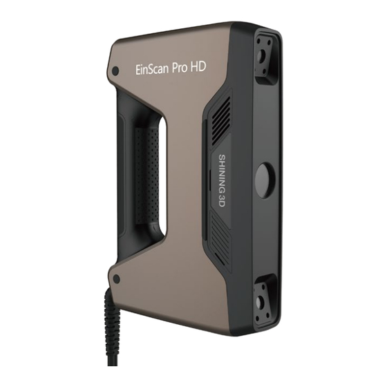
2 Device Introduction Inherited multi-functional and modular design of EinScan Pro series handheld 3D scanner, EinScan Pro HD delivers unparalleled performance in capturing high resolution and accuracy by handheld scanning. Exceptional versatility and powerful optimizations come together for the ultimate high-efficiency and professional-grade 3D scanning experience. - Page 6 Caution Please only use water to clean the calibration board, avoid touching any corrosive liquid. Industrial Pack (optional) Color Pack (optional)
- Page 7 Connection Turn on the device and connect it to the computer through USB 3.0 port. Warning Make sure you are using the correct power adapter. If you use a turntable, you need to connect the turntable power and data cables separately. Add-ons Industrial pack color pack...
- Page 8 Compatible with multiple scanning modes, including Fixed Scan, Handheld HD Scan and Handheld Rapid Scan. Compatible with multiple align modes, including Features, Markers, Texture alignment (with the color pack applied) and Hybrid alignment modes. Industrial Pack Installation 1. Remove the quick release plate from the tripod, fasten it onto the scanner tray, and fasten the scanner tray onto the tripod, then place the scanner on the tray.
-
Page 9: Software Installation
2. Insert the Color Pack and lock it with a rotary lever. 3 Software Installation To use the scanner, you need to install the EXScan Pro software first (hereinafter referred to as "the Software"). 3.1 Recommended PC configuration... -
Page 10: Cpu
Configuration Recommendation Operation Window 10 (64-bit) and Window 11 Pro (64-bit). System Intel® Core™ i7-11700 or above. Note Improper computer configuration or hardware issues will cause CPU performance degradation and affect the user experience, and it is recommended to use the CPU-Z tool to check CPU performance before starting scanning, for more see CPU. -
Page 11: Gpu
3.1.2 GPU It is necessary to use a NVIDIA discrete graphics card for the scanner. Note The NVIDIA discrete graphics card should support CUDA10.2 or above; you can use NVIDIA Control Panel > Help > System information > Components to get the CUDA version with follow steps. Use a discrete graphics card on desktop Connect your monitor to the port of discrete graphics card on the back of your computer, and OS will use the discrete graphics card automatically. -
Page 12: Software Installation
4.1 Online Activation If your computer is currently connected to the internet, please enter your account information in the Shining 3D Passport pop-up window that appears when you start the software, and click Login. The device will then automatically complete the activation process. -
Page 13: Offline Activation
Note For new users, you need to register a Shining 3D User Account first: click Register in the pop-up window when launching the software, or click Sign Up in our Shining 3D Passport official website Please read and then check Privacy Policy and Terms of use. -
Page 14: Software Interface
Note If you are a new user, please register a Shining 3D Passport account first. 4.Copy the V2C file to the computer without no network and import the file into the software. Note If you fail to activate the device in neither way, please contact your supplier or... - Page 16 ...
- Page 17 Refresh to trigger detection again. Support: provide the entrance to check user manuals and start up the Teamviewer (for remote assistance), and contact information for technical support. Shining 3D Passport: provide the entrance to login/logout, My Shining 3D account, Official Website and official Facebook...
-
Page 18: Mouse
Scanning Settings Camera Window: accurately adjust the parameters by previewing the actual scene through the camera window in the scanning process. Project Group: project group management module, refer to Project and Project Group for more information. Scanning parameters: set scanning parameters, refer to Scanning Settings for more information. - Page 19 Steps: 1. Take out the Space Mouse from its packaging. 2. Insert the connecting cable into a USB port on your computer. 3. Download and install the latest version of the 3Dconnexion software 4. Run the software. Software Interface...
- Page 20 Icon Description Click to open the 3Dconnexion quick training and guide. Click to view the 3Dconnexion product user manual. Click to open the settings panel and customize the button functions. Use 3Dconnexion Viewer to view 3D models. Supports STP, STEP, IGS, IGES, OBJ, STL, PLY, JT, and GLTF formats.
- Page 22 Button Description Color Display Screen Number 12 additional programmable function buttons. You can customize their functions using the Buttons 3Dconnexion settings. Refer to Number Buttons for specific operations. Custom View In this scanning software, long press to save the current view of the model (angle, position, Button zoom, etc.), or single click to switch to the saved view.
- Page 23 Icon Shortcut Function Toggle selection of markers/point clouds (only works in Scan). ⌃ C t r l Toggle selection of penetration/non-penetration (only works in Post- ⌃ C t r l processing). Toggle selection mode for data. For more selection modes, please refer ⌃...
-
Page 24: Calibration
Icon Description Tilt left or right button to adjust the model on the Z-axis. Rotate button to adjust the model on the Y-axis. Tilt forward or backward button to adjust the model on the X-axis. Push forward or pull backward button to zoom in or out the model. Push up or push down button to move the model up or down. - Page 25 With calibration, the scanner parameters are recalculated, which not only ensures the accuracy of the scanner, but also improves the quality of scanning. Thus, it is recommended to calibrate the device before each use. Calibration is required under the following conditions: When the scanner is used for the first time or there are more than 7 days since last calibration.
- Page 26 1.Place the calibration board with the front side (black background with white dots) facing up, flat on the table, and align it in the same orientation as shown in the diagram. 2.After picking up the scanner, move it above the calibration board. The scanner should be positioned vertically, facing directly towards the table, in the same direction as shown in the diagram.
-
Page 27: Accuracy Evaluation
Note Lift the scanner up when the interface shows too close; move the scanner down when the interface shows too far. 5.Please continue to follow the instructions provided by the software to complete the subsequent steps. Warning For positions 2 to 5, you will need to use the calibration board stand. You need to click button again to start capturing images for the new position. - Page 28 Note If the detected error is greater than 0.05 mm, it is recommended to perform a recalibration. 1.Place the calibration board with the front side (black background with white dots) facing up, flat on the table, and align it in the same orientation as shown in the diagram.
-
Page 29: White Balance
9 White Balance If the color pack is applied, you need to calibrate white balance, in order to calibrate the texture camera for the first use; when the texture scanning effect is not satisfactory in the subsequent scan, it is recommended to calibrate again. -
Page 30: Scanning
2.Point the scanner to the calibration board, and click Click to start or press button on the scanner to start calibration. 3.Hold the scanner and steadily move up from the bottom until one box is ticked. III. Scanning 10 Scanning Procedure Three scan modes are supported: Fixed Scan、Handheld HD Scan and Handheld Rapid Scan. - Page 31 Fixed Scan New/Open project group use the turntable Ye s Choose align mode Adjust angle and distance Adjust brightness Start scan Edit scanning data Continue scanning Ye s Automatic alignment succeeded? Manual alignment Scan&alignment completed? Ye s Global optimization & generate point cloud and save point cloud data(ASC) Mesh model (watertight/unwatertight)
-
Page 32: Preparation
Handheld HD Scan / Handheld Rapid Scan New project group Open project group Choose operation mode, mode of alignment, resolution and texture Preview and adjust brightness Start scanning Pause scanning Edit scanning data Continue scanning Generate point cloud and save point cloud data (ASC) Mesh model (watertight/unwatertight) Save data... -
Page 33: For Markers
Note Objects that are not recommended for scanning include: (In the Fixed Scan mode) Moving or vibrating objects, which cause the shape of object changed during scanning process. Soft material object that cannot be hung. Lattice structures with many small deep holes. 11.1 For Markers If the features of the scanned object are not rich enough, markers (3 mm) can be pasted on the object for scanning alignment. -
Page 34: Project And Project Group
Object Preparation Notes while scanning Transparent, shiny, reflective or Use washable or vanishing scanning spray. Scan as normal after black objects spraying. Thin wall objects Place markers on and around the objects and Scan as normal after select Markers mode. preparations. -
Page 35: Project
12.1.1 New Project Group To create a project group, please refer to two ways as follows: In the navigation bar, enter the Scan Mode step and select the scan mode. In the pop-up window, click on New project group. In the file dialog that appears, enter the name and path for the project group, then click Confirm. -
Page 36: Project Settings
Icon Function Description Notes Create new Click this button will create a new project You can only create a new project within the current project group. project when a device is connected. The last project in the project list is the current project, and only the current project can continue scanning. - Page 37 Texture Scan Texture Icon Description Texture Scan During the scanning process, you can simultaneously capture texture information to assign color to the data. Note If you want to choose the texture scan, please ensure that a color pack is installed. Non-texture Get the texture without color.
- Page 38 Align mode Description Features Automatically complete the alignment by the surface geometric features of the scanned object. This mode is used for objects that cannot paste markers and have rich surface features. Texture Texture alignment is a technique that utilizes the surface texture features of the scanned object to alignment automatically complete the alignment and merging process.
- Page 39 Select Mode of Alignment Align mode Description Features Automatically complete the alignment by the surface geometric features of the scanned object. This mode is used for objects that cannot paste markers and have rich surface features. Texture Texture alignment is a technique that utilizes the surface texture features of the scanned object to alignment automatically complete the alignment and merging process.
-
Page 40: Start Scanning
Note Under static object scanning scenarios, it is not recommended to enable this feature. Not applicable with Marker or Hybrid Alignment mode. III.I Start Scanning 14 Scanning Settings After entering the Scan step interface, you can perform scan settings on the left side of the interface. Fixed Scan Camera Window Preview the real-time image captured by the scanner camera. - Page 41 With Turntable (optional) With this feature being enabled, the turntable can be used to help scanning. Please select Align Mode (Hybrid is not supported) first before choosing to use the turntable. After scanning a full circle, you can reselect the stitching mode. Number of rotations: Before scanning, you can set the number of rotations for the turntable (8 ~ 180), with a default value of 8.
- Page 42 Brightness is too high Brightness is normal Brightness is too low Plane Detection With this feature being enabled, the software will automatically detect and erase the plane where the object is located. This helps reduce the chances of misaligning planes or objects with distinct features. Note If you need to scan objects that are flat or have few features, it is recommended to paste markers for helping alignment.
-
Page 43: Scanning
Note The unique plane marked during the scanning preview can change in real-time. The plane marked as the last one at the end of the scanning preview will be considered. This feature is disabled by default, and plane detection is enabled by default. If the Cutting Plane feature is used, this feature cannot be used. -
Page 44: Generate Point Cloud
Function Icon Description Preview Preview scanning effect. Note In this mode, the scanning data will not be saved and scan parameters be adjusted according to the scanning effect. Start Scan Scan the objects. Note In this mode, the scanning data will be saved. In the Fixed Scan mode, you can press to start scanning. -
Page 45: Bottom Panel
When you start Scanning, you can conduct Data Editing in Scan to generate accurate point clouds. You can also other functions. 16.1 Bottom Panel You can use following tools to edit data after the scanning paused or the point cloud is generated. - Page 46 ...
- Page 47 Icon Function Instruction Perspective The object appears larger when closer, and smaller when farther away. View Orthogonal The object does not appear larger when closer, and smaller when farther View away. Multi View Observe the data from 6 different views. Cutting Plane Create a Cutting Plane...
- Page 48 Up to 200 frames of data can be rewound. Rectangular Select/Deselect a rectangular area. The selected area is displayed in red. Polygon Select/Deselect a polygon area. Lasso Select/Deselect the area by using the Lasso tool. Straight line Move the cursor to draw a straight line to select/deselect the area. Brush Hold down and a red circle will appear.
-
Page 49: Right Panel
16.2 Right Panel You can use more functions on the right panel in Scanning. Icon Function Instruction Project Group Create / open a project group. About project group, please refer to Project Group. Align Align the data as you need, please refer to Align. Save Data Save scan data. -
Page 50: Cutting Plane
Shortcut Function Press and hold the and move the cursor Rotate the data L e f t B u t t o n Press and hold the and move the cursor Translate the data M i d d l e B u t t o n Hold down Select the area of data ⇧... -
Page 51: Alignment
Note It is not supported to deleted all point cloud data. At least four markers should be remained at the front appearance of the cutting plane. Translate the cutting plane: after generating the plane, you can enter numbers or drag the arrow of the cutting plane's normal in the editing box to translate the cutting plane. -
Page 52: Post Processing
Mode Description Note 1. Choose By Feature. Objects that have repeatable features (like rounds or rings) or small objects 2. Select the project which needs alignment in the are not suitable for this mode. fixed window and the floated window. By Feature 3. -
Page 53: Mesh Optimization
Icon Function Instruction Unwatertight Unclosed model stays the way it is scanned. Processing time is quicker than Watertight. Half- Some holes will be filled. watertight Watertight All holes will be filled automatically. The data can directly be 3D printed. (default) Only watertight mesh can set model quality: High, Med(default), Low. - Page 54 Set value as 50 Set value as 100 Original data 18.2.4 Simplification Set the triangle number (disenabled by default. If enabled, the default value is 20 with a range of 0 to 99). Note When the simplification is greater than the maximum triangles, prioritize the simplification. 18.2.5 Maximum triangles Disabled by default.
-
Page 55: Operation
Note In the Markers mode, this function is enabled as default for unwatertight or half-watertight models, and can not be disabled for watertight models; otherwise, this function can not be enabled. 18.2.8 Recommended Parameters When turning on, it will automatically use the recommended parameters for meshing. 18.3 Operation 1. - Page 56 ...
- Page 57 Optimization Description Instructions options Texture Brightness and Contrast can be adjusted. Only project files that exclusively contain textures are accessible to this function. Simplification Simplify the model data as the triangular mesh Over-simplification will result in the generated from the scan is in a large size. loss of data details.
-
Page 58: Bottom Panel
number of holes filled will be displayed on the Manually save the post-processing data. interface. Flip Normal To redefine the front direction of the scanned Texture blending should be performed data in reversal design. first as it is not accessible after flip Hold to select normal. -
Page 59: Right Panel
Note The other editing functions are the same as point cloud editing 19.3 Right Panel Icon Function Instruction Open file Open a file (STL, OBJ, PLY) for post processing. Save Data Save scan data to a location in the specified format. Sketchfab Use your Sketchfab... -
Page 60: Shortcuts
Function Instruction Select all/Unselect/Invert/Delete See in data editing and perform by using shortcuts. selected data Fitting view Display the data in the center according to the appropriate size. Select visible, select through See in data editing. Switching the display type You can select different display types(triangles, wireframe, point cloud data as well as triangles and wireframes) and the data display mode of the 3D scene will change synchronously after switching. -
Page 61: Create Feature
20 Create Feature After scanning some data, you can click Measurement on the navigation bar, import the data, and select the data to Create Feature and so on. On the right panel of measurement, click and a Create Feature window will pop up on the left. Note You can switch to Feature List to check the created features;... - Page 62 Creation Description Note Method Select Points Click the data or existing feature points to select the point. Click Create and create a feature point. Select Markers Click existing markers to select You can select Markers to create feature points for the point.
- Page 63 Creation Description Note Method 2 points Click the data or existing feature points to select the point. You can tick the checkbox before From or to and re-select the feature points. Click Create and create a line. Markers Click existing markers and select feature You can select Markers to create a feature points.
- Page 64 Creation Description Note Method 3 Points Click the data or existing feature The three points can't be in a line. points to select the point. Tick the checkbox before the three points and re-select the point. Click Create and create a plane. Point-Line Click existing feature lines or choose The point can't be in the line.
-
Page 65: Align
21 Align After scanning some data, you can click Measurement on the navigation bar, import the data, and select the data to carry out Align and so on. On the right panel of Measurement, Click and a Align window will pop up on the left. Note You can import the un-meshed data in Measurement, align the data and return to scan... - Page 66 Input value and adjust coordinates Input values in Offset or Rotation, and click Move to to align model center with input coordinates and axis direction with rotation value. Note Global coordinate system (disabled by default and need to be enabled manually) is the coordinate system on the right,in which red points to positive X-axis, green points to positive Y-axis and blue points to positive Z-axis;...
-
Page 67: Measurement Tool
Note Global coordinate system (disabled by default and need to be enabled manually) is the coordinate system on the right,in which red points to positive X-axis, green points to positive Y-axis and blue points to positive Z-axis; if the global coordinate system does not appear on the interface, roll the mouse wheel to zoom out the model. Click Align to move coordinate axes. - Page 68 After scanning some data, you can click Measurement on the navigation bar, import the data, and select the data to carry out Measurement and so on.You can calculate surface distance between data, surface area of selected area, and the volume of watertight model. On the right panel of Measurement, click and a Measurement window will pop up on the left.
-
Page 69: Save
Calculate selected area of the scanned model. You can use edition tools, right panel, or shortcuts on the bottom panel to select the area. Click Calculate and the area will show itself with a unit of mm². Click Close and close the front window. Note This function is only available for meshed models. -
Page 70: Share Data
You can save the scan data. In the Scan, Post-processing, or Measurement interface, click to select the save path and the file format, enter the file name as well. Format Data Type Saved as Application ASC (whole Optimized cloud Scan.asc Check the data;... -
Page 71: Third-Party Softwares
Export data to Geomagic Control X Metrology Export data to Verisurf Metrology Export data to Geomagic Design X Reverse Engineering Export data to Geomagic Essentials Mesh Editing Export data to Solid Edge SHINING 3D Edition Reverse Engineering QUICKSURFACE Reverse Engineering... -
Page 72: Contact Us
Email: einscan_support@shining3d.com Support platform: https://support.einscan.com Shining 3D Offices APAC Region & Headquarters SHINING 3D Tech Co., Ltd. Hangzhou, China Phone: +86 571 82999050 Add: No. 1398, Xiangbin Road, Wenyan, Xiaoshan, Hangzhou, Zhejiang, China, 311258 EMEA Region SHINING 3D Technology GmbH.
Need help?
Do you have a question about the EinScan Pro Series and is the answer not in the manual?
Questions and answers