
Related Manuals for JWA PADILLA 75138


Summary of Contents for JWA PADILLA 75138
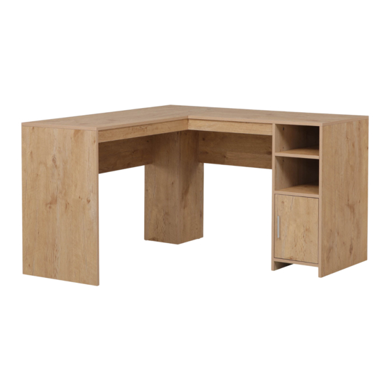
- Page 1 PADILLA Corner Desk ITEM CODE 75138 Imported by JWA Furniture Pty Ltd, Qld, Brisbane Australia. For any assistance with assembly or for missing parts please refer to your receipt...
- Page 3 8X30mm M3.5X14mm M4X18mm 2pcs 53pcs 14pcs 16pcs 2pcs ST3.5X18mm 4pcs 6pcs 6pcs ST4X25mm 2pcs 2pcs...
- Page 4 Top left panel Right back panel Cabinet left panel Top right panel Support panel Cabinet right panel Layer panel Left side panel Left back panel Left front baffle panel Cabinet top panel Back left side panel Right front baffle panel Back right side panel Cabinet bottom panel Cabinet front panel...
- Page 5 1. Insert parts A and B into panel 6 and 7. 1. Attach panels 14 and 15 to panels 6 and 7 with parts A and B.
- Page 6 1. Slide panel 17 along slots of panels 6 and 7. 2. Attach panel 12 to panels 4 and 5 with part A. 1. Attach panel 9 to panel 10 with part A. 2. Attach panel 10 to panel 8 with part A.
- Page 7 STEP 5 1. Attach panel 4 to panel 5 with part A. 2. Insert part A into panel 3. STEP 6 1. Attach panels 8 and 9 to panel 3 with part A. 2. Attach panel 8 to panel 4 side from component in Step 5.1.
- Page 8 STEP 7 1. Attach panel 11 to panel 5 with part A. 2. Attach panels 10 and 11 to panel 6 with part A. STEP 8 1. Insert parts A & B into panel 1. 2. Flip over panel 1 and attach to left side of desk and secure with part A cam locks.
- Page 9 STEP 9 1. Insert parts A & B into panel 2. 2. Flip over panel 2 and attach to right side of desk and secure with part A cam locks. STEP 10 1. Attach part F to panel 16 with part C.
- Page 10 STEP 11 1. Attach part J to panel 6 with part D. STEP 12 1. Attach the right side of part E to panel 16 with part D. 2. Attach the left side of part E to panel 7 with part D.
- Page 11 STEP 13 1. Insert part I inside panels 6 and 7, then place panel 13 on top. Adjust shelf height to personal preference. STEP 14 1. Attach part H to panel 17 with part G.
- Page 12 STEP 15 Install Tip Kit 1. Attach part L to the back of panel 1 with part D. 2. Attach part L to the wall with part K. STEP 16 Assembly complete!
Need help?
Do you have a question about the PADILLA 75138 and is the answer not in the manual?
Questions and answers