Table of Contents

Subscribe to Our Youtube Channel
Related Manuals for RDZ CHR 400 CoRe


Summary of Contents for RDZ CHR 400 CoRe
- Page 1 Air Handling Units Unità Trattamento Aria CHR 400 CoRe Mechanical ventilation with heat recovery appliance Ventilazione meccanica con sistema di recupero di calore INSTALLATION / TECHNICAL MANUAL MANUALE INSTALLAZIONE / TECNICO...
-
Page 3: Avvertenze Per La Sicurezza
SAFETY WARNINGS - AVVERTENZE PER LA SICUREZZA Read this manual carefully before installing and/or using the Le g g e re co n at te n z i o n e q u e s to l i b re t to p r i m a equipment and keep it in an accessible place. -
Page 4: Avvertenze Generali
GENERAL WARNINGS - AVVERTENZE GENERALI • If, after having unpacked the equipment, any anomaly is noted, • Se dopo aver disimballato l’apparecchiatura si nota una do not use the equipment and contact an Assistance Centre qualsiasi anomalia non utilizzare l’apparecchiatura e rivolgersi authorised by the manufacturer. -
Page 5: Table Of Contents
PRELIMINARY OPERATIONS OPERAZIONI PRELIMINARI GENERAL OVERVIEW PANORAMICA GENERALE Description Descrizione Features And General Notes Caratteristiche e Note Generali CHR 400 CoRe Package Content Contenuto Imballo CHR 400 CoRe Accessories Accessori CHR 400 CoRe Components Componenti CHR 400 CoRe INSTALLAZIONE INSTALLATION... -
Page 6: Operazioni Preliminari
PRELIMINARY OPERATIONS - OPERAZIONI PRELIMINARI TESTING, TRANSPORT AND UNPACKAGING ISPEZIONE, TRASPORTO E DISIMBALLO Upon receipt, check immediately that the packaging is intact: All’atto del ricevimento verificare immediatamente l’integrità the machine has left the factory in perfect working order and any dell’imballo: la macchina ha lasciato la fabbrica in perfetto stato, damage must be notified to the carrier immediately and noted on eventuali danni dovranno essere immediatamente contestati... -
Page 7: Panoramica Generale
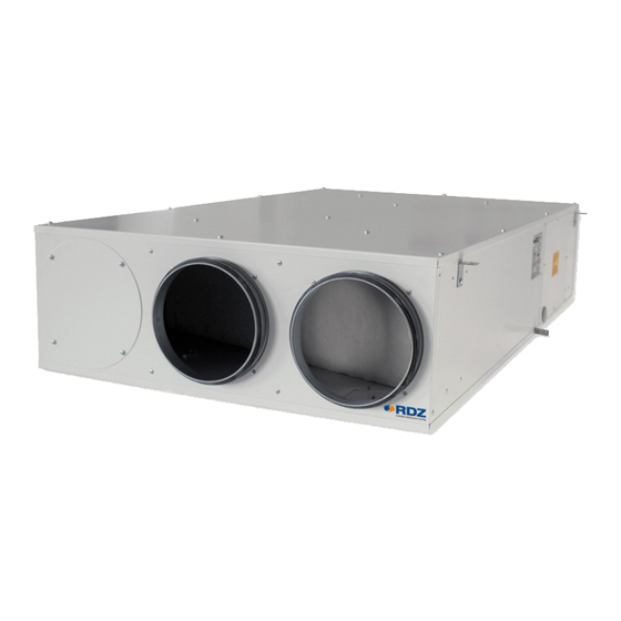
FEATURES AND GENERAL NOTES - CARATTERISTICHE E NOTE GENERALI The CHR 400 CoRe appliance is a key part of a whole house Il CHR 400 CoRe è un componente chiave del sistema di ventilation system specifically designed to improve indoor air ventilazione della intera casa specificatamente progettato per quality in dwellings. -
Page 8: Descrizione
SF-P Condensate drain kit with casing, designed for wall installation. It can be used in combination with RDZ air handling units, and it is suitable for Ø 20-32 mm piping. The external shell can be adjusted considering the thickness of the wall. Washable Internal Cartridge. -
Page 9: Componenti Chr 400 Core
7044105 Kit per la sostituzione completa dei filtri dell’unità contenente: • 1 filtro ISO Coarse 50% + 1 filtro ISO Coarse 65% + 1 filtro ISO ePM CHR 400 CORE COMPONENTS - COMPONENTI CHR 400 CORE Rif. Descriptions Descrizione Supply Air fan... -
Page 10: Installazione
Additionally, both ducts al fine di rispettare i regolamenti edilizi. connecting the CHR 400 CoRe to outside must be insulated when Usare sempre gli isolamenti sulle linee di Estrazione-Espulsione passing through heated areas to avoid condensation forming on aria esterna e Immissione aria ambiente quando attraversano the outside of the ducts. - Page 11 Fresh Air Inlet Exhaust Air Stale Air Extraction Supply Air Ingresso Aria Esterna Espulsione aria Estrazione aria viziata Immissione Aria Fresh Air Inlet Supply Air Ingresso Aria Esterna Immissione Aria Outside Inside Inside Esterno Interno Interno Stale Air Extraction Exhaust Air Estrazione aria viziata Espulsione aria Inside...
- Page 12 Positioning indications & Minimum space allowanceses Indicazioni di posizionamento & Distanze minime di rispetto HORIZONTAL POSITIONING POSIZIONAMENTO ORIZZONTALE ≥ 60 cm Exhaust Espulsione Inlet Exhaust Immissione Espulsione ≥ 60 cm Inlet Immissione Exhaust Inlet INSIDE OUTSIDE Immissione Espulsione INTERNO ESTERNO VERTICAL POSITIONING POSIZIONAMENTO VERTICALE Inlet...
-
Page 13: Posizionamento E Fissaggio A Soffitto
POSITIONING AND FIXING TO THE CEILING POSIZIONAMENTO E FISSAGGIO A SOFFITTO CAUTION ATTENZIONE • Installation and maintenance must be carried out by • L’installazione e la manutenzione vanno eseguiti solo qualified personnel only. Throughout installation, make sure da personale qualificato. Durante tutte le procedure di that the equipment is not connected to the electrical mains. - Page 14 ø8mm Rubber mounts Gommino antivibrante Fixing to ceiling Washer Rondella Fissaggio a so tto min. 50 cm Trap door Botola d’ispezione...
-
Page 15: Collegamenti Idraulici
RDZ condensate drain kits (SF-P / SF-M 13). According esigenze, fra i kit di scarico condensa RDZ disponibili to the model chosen, respect the installation (SF-P / SF-M 13). - Page 16 SF-P Cod. Condensate drain kit with casing, designed for wall installation. It can be used in combination with RDZ air handling units, and it is suitable for Ø 20-32 mm piping. The external shell can be adjusted considering the thickness of the wall. Washable Internal Cartridge. For information see the dedicated technical sheet.
- Page 17 RDZ air handling units. 3600401 Kit di scarico condensa composto da sifone con membrana in silicone, tubo e raccordo, da utilizzare in abbinamento alle unità di trattamento dell’aria RDZ. NOTE AGGIUNTIVE PER INSTALLAZIONE KIT SCARICO RDZ ADDITIONAL NOTES FOR RDZ DRAIN KIT INSTALLATION •...
-
Page 18: Collegamenti Elettrici
ELECTRICAL CONNECTIONS - COLLEGAMENTI ELETTRICI INSTALLATION INSTRUCTIONS INDICAZIONI DI INSTALLAZIONE The unit must be connected to a disconnected, earthed L’unità deve essere collegata ad una presa di power socket. The electrical system must be protected against corrente sezionata provvista di terra. L’impianto elettrico di overloads, short circuits and direct and indirect contacts and alimentazione deve essere protetto contro i sovraccarichi, i comply with the laws and regulations in force in the country of... - Page 19 OVERVIEW OF THE ELECTRONIC BOARD UNIT PANORAMICA SCHEDA ELETTRONICA A BORDO B - RX (-) A - TX (+) AI0 AI1 AI2 AI3 AI4 AI5 DI0 DI1 DI2 DI3 DI4 Descriptions Descrizione 5 electro-mechanical relay digital outputs (max 2 A) 5 uscite digitali a relè...
- Page 20 LEDS DESCRIPTION ON THE ELECTRONIC BOARD UNIT DESCRIZIONE DEI LED SULLA SCHEDA ELETTRONICA Legend - Legenda L.O. L.G. GREEN - OPERATION LED (D5) VERDE - Led FUNZIONAMENTO L.O. ORANGE - LED ALARMS (D35) ARANCIONE - Led ALLARMI L.R. RED - LED ERRORS (D4) ROSSO - Led ERRORI B - RX (-)
- Page 21 Problem - Causes - Cause Remedies - Rimedi Problema Dirty fan Clean the fan Ventilatore sporco Pulire il ventilatore. Damaged impeller Check the integrity of the fan Girante danneggiata Verificare l’integrità del ventilatore Portata aria scarsa o assente Clogged fan ducts Clean/clean the ventilation ducts.
- Page 22 POWER SUPPLY ALIMENTAZIONE Connect the 3 terminals with Ø 1 mm cable: Portare e collegare i 3 morsetti con cavo Ø 1 mm phase (F) , neutral (N), ground fase (F) , neutro (N), terra Alimentazione Power Supply 230V 50Hz NEUTRAL - NEUTRO PHASE - FASE GROUND - TERRA...
- Page 23 DIGITAL INPUTS / COMANDI DIGITALI DIGITAL INPUTS COMANDI DIGITALI DIGITAL OUTPUTS (max 2 A) USCITE DIGITALI FILTERS ALARM ALLARME FILTRI (max 2 A) ELECTRICAL PRE-HEATING PRE-RISCALDO ELETTRICO 230 V DIGITAL INPUTS INGRESSI DIGITALI 3 SPEED SWITCH DI0 DI1 DI2 COMMUTATORE 3 VELOCITA’ V1 V2 V3 V3 = if impulse-controlled, switch-o occurs after 15 minutes (BOOST function) V3 = se comandato ad impulso lo spegnimento avviene dopo 15 minuti (Funzione BOOST)
- Page 24 INSTALLATION WITHOUT REMOTE CONTROL INSTALLAZIONE SENZA CONTROLLO REMOTO In the case of installation without any remote control, the Nel caso di installazione senza nessun controllo remoto dirty filter alarm must be installed as shown in the diagram deve essere installata la segnalazione dell’ allarme filtri below.
- Page 25 SWITCH SETTING R-BUS +12 Vdc 0 Vdc CHR 400 CoRe CORE AIR SPEED / CORE AIR CONTROL - The communication cable between the various nodes is a 2 x 0,5 mm twisted and shielded cable; - In-out connection; - The shield must be connected by creating continuity between the various pieces of cable and grounded at one point in the network.
-
Page 26: Funzionamento
FUNCTIONING - FUNZIONAMENTO (*) For the Fresh Air Inlet it is possible to choose between the default (*) Per l’ Ingresso Aria Esterna è possibile scegliere fra la position and the ALTERNATIVE one, by swapping the position of posizione di default e quella ALTERNATIVA, scambiando di the collar and the air filter. - Page 27 RENEWAL (V2) RINNOVO (V2) The system is designed to provide measured amounts of filtered, Il sistema è progettato per fornire un valore misurato di fresh air to living areas while constantly removing polluted, stale aria pulita e filtrata nelle stanze abitate mentre rimuove air from bathing, cooking and washing areas at the same gentle continuamente l’aria esausta e sporca da bagni,cucina e aree rate.
- Page 28 FREE-COOLING FREE-COOLING This model is supplied with motorized damper. If Free-Cooling Questo modello è fornito con una serranda motorizzata is ON, the fresh air from outside is not pre-heated in the heat attivabile automaticamente. Quando la funzionalità di Free recovery unit from the expulsion air. Cooling è...
-
Page 29: Manutenzione
Vacuum cleaning is allowed. After 3 consecutive cleaning filtri a bordo macchina). È consentito pulire i filtri a vapore. operations, filters must be replaced. Contact RDZ to purchase new Dopo un ciclo di 3 pulizie consecutive i filtri devono essere filters. - Page 30 CLEANING THE EXCHANGER PULIZIA SCAMBIATORE Warning: the heat exchanger have to be cleaned every 2 years by Attenzione! La pulizia dello scambiatore di calore va effettuata removing the bottom panel from the unit. ogni due anni e avviene rimuovendo il pannello inferiore dell’ unità.
-
Page 31: Manutenzione Straordinaria
EXTRAORDINARY MAINTENANCE / MANUTENZIONE STRAORDINARIA REMOVING THE FAN RIMOZIONE VENTILATORE Caution! To replace the fan you must remove the lower panel. Attenzione! La sostituzione del ventilatore avviene rimuovendo il pannello inferiore. OFF! x 16 Disconnect and remove the power supply and fan control cables from the electrical panel (see wiring diagram). -
Page 32: Dati Tecnici E Prestazioni
TECHNICAL DATA AND PERFORMANCE - DATI TECNICI E PRESTAZIONI DIMENSIONS / DIMENSIONI [mm] 1014 Ø200 Ø200 1134 1313 1395 Overall machine dimensions Ingombri della macchina Height Altezza Width Larghezza Depth Profondità 1395 Weight Peso 46,6 • Nominal air flow 400 m³/h with 200 Pa •... -
Page 33: Prestazioni Secondo (Ue) N. 1254/2014
Filter alarm reset via room controller q) Segnale visivo su controllo ambiente r) not applicable r) Non applicabile s) Recycling disassembly instruction - go to www.rdz.it s) Istruzioni per lo smaltimento -vai a www.rdz.it t) not applicable t) Non applicabile... - Page 34 Cold - Freddo 8465 8521 8633 8857 Average - Temperato 4327 4356 4413 4528 Warm - Caldo 1957 1970 1996 2047 ENERGY LABEL ETICHETTA ENERGETICA RDZ S.p.A. CHR 400 CoRe ENERGIA · · ΕΝΕΡΓΕΙΑ · ENERGIJA · ENERGY · ENERGIE 2016 1254/2014...
-
Page 35: Prestazioni Aerauliche
AERAULIC PERFORMANCE / PRESTAZIONI AERAULICHE Inlet Fan - Ventilatore Immissione V1 RID. V2 RID. V3 RID. Electric Consumption Consumo Elettrico 71 W 129 W 83 W 147 W 96 W 150 W 108 W Air ow - Portata aria (m /h) Exhaust Fan - Ventilatore Espulsione V1 RID. -
Page 36: Schemi Elettrici
WIRING DIAGRAMS - SCHEMA ELETTRICI CHR 400 CoRe SCHEMA ELETTRICO - WIRING DIAGRAM Marrone-Brown Blu-Blue Bianco-White DANGER 230 VOLTS ! Alimentazione Power Supply 230V 50Hz Giallo/Verde-Yellow/Green (PE) Blu-Blue (N) Marrone-Brown (L) B - RX (-) A - TX (+) L.O. - Page 40 CLICK | SCAN qr.rdz.it/?qr=P644 FAG0CB006AB.00 05/2023...
Need help?
Do you have a question about the CHR 400 CoRe and is the answer not in the manual?
Questions and answers