Table of Contents
Advertisement
Available languages
Available languages
Quick Links
Advertisement
Table of Contents

Related Manuals for RDZ WHR 61


Summary of Contents for RDZ WHR 61
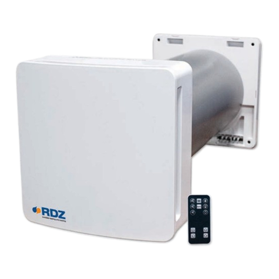
- Page 1 Air Handling Units Unità Trattamento Aria WHR 61 Mechanical ventilation with heat recovery appliance Ventilazione meccanica con sistema di recupero di calore TECHNICAL/INSTALLATION MANUAL MANUALE TECNICO/INSTALLAZIONE...
- Page 3 INTRODUZIONE Questo manuale tecnico contiene descrizioni tecniche, operazioni di installazione, montaggio, manutenzione e dati tecnici esclusivamente rivolti al personale qualificato addetto alla installazione e manutenzione del prodotto. DESTINAZIONE D’USO Il prodotto è costruito a regola d’arte e viene installato per dare la possibilità di un ricambio costante di aria all’interno della stanza.
- Page 4 CONTENUTO 1- Frontale estetico copertura serranda 7- Scambiatore ceramico l i F i r t à t i l l a 4i- Fissaggio a parete interno con connessioni 10- Avvertenze generali elettriche 11- Foglio di garanzia RAEE 4e- Fissaggio a parete esterno 12- Imballo prodotto a i l 6- Tubo da incasso 500mm...
-
Page 5: Parametri Tecnici
Il recuperatore è stato progettato per installazioni in luoghi chiusi. Le temperature di esercizio sono comprese tra -20°C e 50°C con umidità relativa massima 80%. Il design del recuperatore è in continua evoluzione, pertanto, alcuni modelli potrebbero differire da quanto descritto nel presente manuale. MISURE, MM WHR 61 Velocità 220-240Vac 220-240Vac 220-240Vac... -
Page 6: Installazione
COSTRUZIONE Il prodotto è costituito da un’ unità principale di funzionamento con attacco a parete che andrà posta all’interno del locale, un tubo da incasso contenente lo scambiatore ceramico ed i filtri, un convogliatore esterno con attacco a parete. Scambiatore Convogliatore ceramico esterno con attacco... - Page 7 1) MONTAGGIO Dopo aver individuato l’area nella quale si intende installare il prodotto segnare il centro del foro passante da realizzare sulla parete. Assicurarsi che, rispetto al centro del foro per il tubo di incasso, ci sia uno spazio libero sulle pareti interne ed esterne per un raggio di 15 cm dal centro, questi corrispondono all’ingombro del prodotto.
- Page 8 M=500mm Una volta adattata la lunghezza del tubo da incasso (6) allo spessore esatto della parete, posizionare il particolare attacco a parete esterno (4e) sulla parete esterna come da immagine riportata di seguito: Inserire il diametro di centraggio dell’attacco a parete (4e) all’interno del tubo da incasso Una volta centrato nel tubo, tracciare i fori di fissaggio sulla parete esterna utilizzando il particolare attacco a parete esterno (4e) aiutandosi con uno strumento di misura di livello per assicurarsi un’...
-
Page 9: Collegamenti Elettrici
Avvitare il particolare attacco a parete esterno (4e) al muro esterno. Fissare a scatto sull’attacco a parete esterno (4e) il convogliatore esterno (5) come da immagini riportate: 2) COLLEGAMENTI ELETTRICI L’installazione dell’apparecchio è destinata solo ed esclusivamente a personale qualificato. Assicurarsi che la tensione di alimentazione del locale di installazione sia conforme all’alimentazione dichiarata sulla targa dati del prodotto. - Page 10 Come per il tracciamento dei fori esterni, inserire prima il diametro di centraggio del particolare attacco a parete interno (4i) all’interno del tubo da incasso (6) come da immagine sopra riportata. Con l’aiuto di uno strumento di misura di livello tracciare e realizzare i 4 fori per il fissaggio a parete del particolare attacco a parete interno (4i).
- Page 11 COLLEGAMENTO DI UN CAVO DI ALIMENTAZIONE PROVENIENTE DAL MURO: Una volta inseriti i tasselli, prima di procedere con il fissaggio, estrarre la morsettiera dal particolare fissaggio a parete interno (4i) e far passare i cavi attraverso l’apposita sede. COLLEGAMENTO DI UN CAVO DI ALIMENTAZIONE ESTERNO: Rompere le linguette di plastica indicate nelle immagini sottostanti.
-
Page 12: Collegamento Alimentazione
Fissare il particolare fissaggio a parete interno (4i) al muro ed effettuare i collegamenti elettrici come descritto nei paragrafi successivi. COLLEGAMENTO ALIMENTAZIONE Prima di procedere con il collegamento è necessario che i cavi di alimentazione (linea e neutro) siano presenti in corrispondenza della zona appositamente ricavata nella parete. Munirsi del particolare fissaggio a parete interno (4i) e degli attrezzi necessari a connettere la rete di... - Page 13 Eseguire i collegamenti come da immagine sotto riportata: COMUNICAZIONE CON PRODOTTI SLAVE Se è stato preventivato di installare uno o più prodotti in cascata all’unità principale o si intende predisporre la connessione per un futuro collegamento si faccia riferimento alle immagini di seguito per permettere la comunicazione tra l’unità...
- Page 14 CONFIGURAZIONE PRODOTTI MASTER – SLAVE Verificare che l’unità master non abbia altri apparecchi connessi nei morsetti (C1 e C2), quindi procedere con la sua accensione. Dopo i primi 10 sec in cui il led rosso rimarrà fisso, il prodotto si configurerà automaticamente come Master.
- Page 15 3) CONCLUSIONE DEL MONTAGGIO Al termine del collegamento, reinserire la morsettiera e i cavi nell’apposito alloggiamento. Inserire lo scambiatore ceramico (7) con i relativi filtri (8), posizionandolo a metà del tubo da incasso (6) come da immagine di seguito: Fissare a scatto l’unità principale (3), insieme ai componenti serranda (2) e frontale estetico (1) già montati su di essa, nell’apposito attacco a parete (4i) fino all’aggancio di tutti i denti.
-
Page 16: Manutenzione
MANUTENZIONE Tutte le operazioni di manutenzione dell’apparecchio sono destinate solo ed esclusivamente a personale qualificato. Assicurarsi che il collegamento di rete nel locale di installazione venga disconnesso prima delle operazioni di manutenzione. Una volta installato, il prodotto deve riportare la disposizione dei componenti come da immagine sopra riportata. - Page 17 2) PULIZIA FILTRI E SCAMBIATORE Estrarre l’unità principale (1+2+3) dalla parete utilizzando un cacciavite piatto per azionare il gancio posto nella parte inferiore centrale del prodotto come illustrato di seguito. Una volta che l’unità funzionante si è sganciata dall’attacco a parete (4i) estrarla con le mani tirando energicamente come da immagine di seguito:...
- Page 18 Estrarre lo scambiatore ceramico insieme ai filtri (8+7+8), tirando verso di se l’apposita corda come da immagine di seguito. Rimuovere i filtri (8) dalla loro sede e pulirli aspirando i residui di sporco tramite un aspirapolvere o lavandoli con acqua corrente, asciugandoli accuratamente prima di riposizionarli. Nel caso i filtri (8) risultino usurati (periodo indicativo 2 anni) cambiarli richiedendoli nuovi al rivenditore.
- Page 19 Durante le operazioni di pulizia/sostituzione dei filtri(8), aspirare anche eventuali residui di sporco nello scambiatore ceramico. NON LAVARE LO SCAMBIATORE CERAMICO CON ACQUA. Una volta realizzate le operazioni di pulizia posizionare i filtri (8) nella loro sede sullo scambiatore (7) inserendo gli spacchi dei filtri sotto alla corda come da immagine di seguito:...
- Page 20 3)PULIZIA SERRANDA E VENTOLA Dopo aver effettuato la pulizia dei filtri e dello scambiatore riposizionarli nella loro sede. Prendere il gruppo unità principale (1+2+3) ed estrarre il particolare copertura estetica (1) estraendo prima i ganci superiori e di seguito quelli inferiori. Attraverso un cacciavite piatto fare leva sui denti di aggancio della serranda (2) per estrarla dall’unità...
- Page 21 Pulire con un panno asciutto le pale della ventola facente parte dell’unità principale (3). 4) RIPRISTINO DEL PRODOTTO DOPO LA PULIZIA Rimontare l’unità principale (3) insieme ai particolari serranda (2) e copertura estetica (1) sull’attacco a parete (4i). ATTENZIONE: Se si effettua la pulizia di più prodotti contemporaneamente, rimontare ciascuna unità...
- Page 22 ISTRUZIONI PER IL CORRETTO FUNZIONAMENTO Accensione Spegnimento (0/1) Nel caso si disponga di una sola unità, accendere il prodotto tramite interruttore “0/1” e di seguito premere un comando da remoto per attivare il funzionamento del prodotto secondo il comando inviato. Nel caso si disponga di più unità, vedere il paragrafo “CONFIGURAZIONE PRODOTTI MASTER-SLAVE”, una volta ultimata questa procedura accendere i prodotti tramite interruttore 0/1 e premere un comando da remoto per attivare il dispositivo.
-
Page 24: Intended Use
INTRODUCTION This manual includes technical descriptions, installation instructions, assembly, maintenance and technical data exclusively directed to qualified personnel involved in the installation and maintenance of the product. INTENDED USE The product is artistically made and installed to allow a constant air exchange inside the room. The recovery system can be generally installed in residential or public places. - Page 25 CONTENT 1- Cosmetic Frontal Cover 7- Ceramic heat exchanger l i F i l l 4i- Internal wall-mounting part with electrical 10- Precautions connections 11- RAEE warranty paper 4e- External wall-mounting part 12- Packaging Warnings for proper unpackaging 6- Recessed duct 500mm...
-
Page 26: Technical Parameters
-20°C and 50°C with maximum relative humidity of 80%. The design of the Heat Recovery System is in continuous evolution, therefore, some models may differ from those described in this manual. DIMENSIONS, MM WHR 61 Speed 220-240Vac 220-240Vac 220-240Vac... -
Page 27: Installation
CONSTRUCTION The product is composed of a wall mounted unit to be placed inside the room, a recessed duct which contains the ceramic heat exchanger and filters and an external wall mounted conveyor. Ceramic heat conveyor External wall mounted conveyor Recessed duct External flter Internal filter... - Page 28 1) ASSEMBLY Once the area of installation is selected, mark the center of the hole to be realized on the wall Make sure that on internal and external walls there is enough space, for a radius of 15 cm from the center, thus corresponding to the product overall dimensions.
- Page 29 M=500mm Once adapted the length of the recessed duct (6) to the exact thickness of the wall, put the external wall- mounting part (4e) on the external wall as shown in the picture below: Insert the centering diameter of the wall- mounting part (4e) inside the recessed duct (6).
-
Page 30: Electrical Connections
Fix the external wall-mounting part (4e) on the external wall. Fix the external conveyor (5) on the external wall mounting part (4e) till the complete assembly, as shown in the pictures below: 2) ELECTRICAL CONNECTIONS Installation must only be carried out by qualified person. Make sure that the voltage of the installation room is in compliance with the value declared on the product label. - Page 31 By using a measure level tool, mark and make four holes to fix on the wall the internal wall- mounting part (4i). Unlike the external wall mounting part, on the internal wall is necessary to bring the power supply conductors to connect them to the stripped wires supplied with the product. Provide an output for the wires, as the highlighted area shown in the picture...
- Page 32 CONNECTION OF A SUPPLY CABLE COMING FROM THE WALL: Once the expansion plugs for the wall mounting are inserted, before proceeding with fastening, extract the terminal box from the internal wall mounting part (4i) and let the cable pass through the dedicated space.
-
Page 33: Power Supply Connections
Fix the internal wall mounting part (4i) to the wall and make the electrical connections as described in the next paragraphs. POWER SUPPLY CONNECTIONS Before proceeding with the connection, make sure that the wires (Live and Neutral) are inside the area specifically obtained in the wall. - Page 34 Connections must be done as shown below: COMMUNICATION WITH SLAVE PRODUCTS If you consider to install one or more products in sequence to the main unit or make the connection in the future, refer to the pictures below to allow the communication between the master unit and the products in sequence It is recommended to use different cable colours to avoid to exchange the wiring connections.
- Page 35 CONFIGURATION OF MASTER- SLAVE Verify that the master unit doesn’t have other products connected to the terminals (C1 and C2), then proceed with the powering. After the first 10 seconds while the red LED will be on, the product will be automatically configured as master. In order to verify that the configuration is ok, once the red light is turned out, press the button “AUTO”.
- Page 36 3) ASSEMBLY CONCLUSION After the connection, carefully arrange the terminal box and the cables in the proper compartment and insert the ceramic heat exchanger (7) with related filters (8), placing it in the middle of the recessed tube (6) as shown in the picture here below: Fix the main unit (3), with its shutter (2) and the cosmetic frontal cover (1) already assembled on it, on the internal wall-mounting part (4i) until complete assembly.
-
Page 37: Maintenance
MAINTENANCE All maintenance operations must only be done by qualified person. Before carrying out any cleaning or maintenance disconnect the main supply. Once installed, the product must have the components placed exactly as shown in the picture here above. 1) MAINTENANCE PERIOD INDICATIONS We recommend to clean the filters (8) and the ceramic exchanger (7) every 3 months. - Page 38 2) FILTERS AND EXCHANGER CLEANING OPERATIONS Pull out the main unit (1+2+3) from the wall using a flat screwdriver to drive the hook placed in the lower middle part of the product as shown in the pictures here below. Once the unit is unhooked from the internal wall-mounting part (4i) pull it out with the hands as shown in the picture below:...
- Page 39 Extract the ceramic heat exchanger together with the filters (8+7+8) by pulling the proper cord towards yourself as shown in the picture below. Remove the filters (8) from their location and clean them by using a vacuum cleaner or even washing them.
- Page 40 During the filters cleaning/replacement operations (8), remove any dirt residues in the ceramic heat exchanger by using a vacuum cleaner. DO NOT WASH UNDER WATER THE CERAMIC HEAT EXCHANGER. Once the cleaning operation has been completed, make sure to re-assemble the filters (8) in their location on the heat exchanger (7) by inserting the filters split under the rope as shown in the picture below:...
- Page 41 3)IMPELLER AND SHUTTER CLEANING Once the cleaning operation has been completed make sure to re-mount the filters and the heat exchanger in their location. Take the main unit group (1+2+3) and remove the cosmetic cover (1) by pulling out the upper hooks firstly and then the lower ones.
- Page 42 Clean the fan blades of the main unit with a dry cloth (3) 4) PRODUCT ASSEMBLY AFTER CLEANING Re-assemble the main unit (3) with the shutter (2) and cosmetic cover (1) on the wall-mounting (4i). ATTENTION: if different products are cleaned at the same time, re-mount every principal unit in the specific compartment from which they had been removed in order to avoid communication problems between Master unit and Slave unit.
-
Page 43: Working Instructions
WORKING INSTRUCTIONS ON/OFF Main Switch (0/1) In case of one unit, turn on the product through “0/1” switch and then set a function by remote to activate the product accordingly. In case of more units, refer to paragraph “MASTER-SLAVE PRODUCTS CONFIGURATION” and, once this procedure is ended, turn ON the products through 0/1 switch and press a function by remote to activate the device. - Page 44 FAG0CB002AB.02 02/2019...
Need help?
Do you have a question about the WHR 61 and is the answer not in the manual?
Questions and answers