Table of Contents

Subscribe to Our Youtube Channel
Related Manuals for RDZ REFLAIR 150 ERV


Summary of Contents for RDZ REFLAIR 150 ERV
- Page 1 Air Handling Units Unità Trattamento Aria REFLAIR 150 - 250 ERV Mechanical ventilation with heat recovery appliance Ventilazione meccanica con sistema di recupero di calore INSTALLATION / TECHNICAL MANUAL MANUALE INSTALLAZIONE / TECNICO...
-
Page 3: Avvertenze Per La Sicurezza
SAFETY WARNINGS - AVVERTENZE PER LA SICUREZZA Read this manual carefully before installing and/or using the Le g g e re co n at te n z i o n e q u e s to l i b re t to p r i m a equipment and keep it in an accessible place. -
Page 4: Avvertenze Generali
GENERAL WARNINGS - AVVERTENZE GENERALI • If, after having unpacked the equipment, any anomaly is noted, • Se dopo aver disimballato l’apparecchiatura si nota una do not use the equipment and contact an Assistance Centre qualsiasi anomalia non utilizzare l’apparecchiatura e rivolgersi authorised by the manufacturer. -
Page 5: Table Of Contents
INDEX - INDICE Description Descrizione Pag. SAFETY WARNINGS AVVERTENZE PER LA SICUREZZA GENERAL WARNINGS AVVERTENZE GENERALI DISPOSAL SMALTIMENTO PRELIMINARY OPERATIONS OPERAZIONI PRELIMINARI GENERAL OVERVIEW PANORAMICA GENERALE Description Descrizione Features And General Notes Caratteristiche e Note Generali REFLAIR ERV Package Content Contenuto Imballo REFLAIR ERV REFLAIR ERV Components Componenti REFLAIR ERV... -
Page 6: Operazioni Preliminari
PRELIMINARY OPERATIONS - OPERAZIONI PRELIMINARI TESTING, TRANSPORT AND UNPACKAGING ISPEZIONE, TRASPORTO E DISIMBALLO Upon receipt, check immediately that the packaging is intact: All’atto del ricevimento verificare immediatamente l’integrità the machine has left the factory in perfect working order and any dell’imballo: la macchina lascia la fabbrica in perfetto stato, damage must be notified to the carrier immediately and noted on eventuali danni dovranno essere immediatamente contestati... -
Page 7: Panoramica Generale
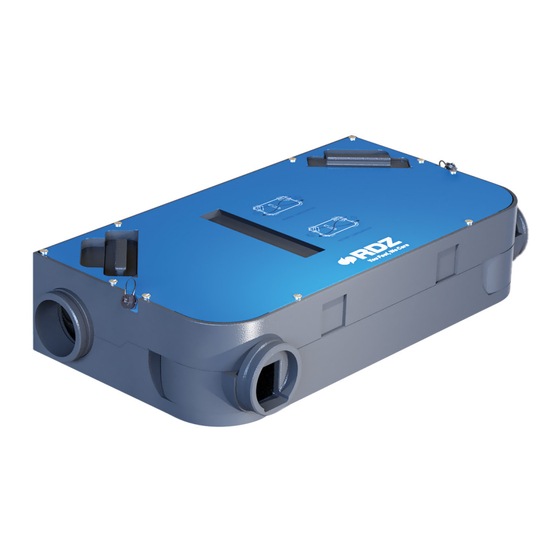
GENERAL OVERVIEW - PANORAMICA GENERALE DESCRIPTION - DESCRIZIONE REFLAIR ERV is a horizontally or vertically installed unit for REFLAIR ERV è una macchina ad installazione orizzontale controlled mechanical ventilation of the environment in the o verticale per la ventilazione meccanica controllata residential sector. -
Page 8: Contenuto Imballo Reflair Erv
REFLAIR ERV PACKAGE CONTENT - CONTENUTO IMBALLO REFLAIR ERV Rif. Descriptions Descrizione REFLAIR ERV Unit Unità REFLAIR ERV Installation template Dima di installazione Fixing brackets with screws Staffe di fissaggio con viti ErP label and data fiche Etichetta energetica ErP Installation / Technical Manual Manuale Installazione / Tecnico 2 x hose connector/cap... -
Page 9: Componenti Reflair Erv
REFLAIR ERV COMPONENTS - COMPONENTI REFLAIR ERV Rif. Descriptions Descrizione Supply Air fan Ventilatore di Immissione Aria Heat recuperator Recuperatore di calore Exhaust Air fan Ventilatore di Espulsione Aria Condensation drain (not used) Scarico condensa (non utilizzato) Wiring box Quadro Elettrico ISO Coarse 65% Air filter Filtro Aria ISO Coarse 65% AIR FLOWS - FLUSSI ARIA... -
Page 10: Complementi
COMPLEMENTS - COMPLEMENTI ACCESSORIES ACCESSORI CONTROL PANELS - PANNELLI DI CONTROLLO Cod. CORE AIR SPEED Room interface to control the air renewal unit and display the related data 7041476 Controllo ambiente per la visualizzazione e l’impostazione del funzionamento dell’unità. CORE AIR CONTROL Graphical interface to manage functioning, scheduling and unit parameters. -
Page 11: Installazione
INSTALLATION - INSTALLAZIONE AERAULIC SYSTEM RETE AERAULICA INSTALLATION INSTRUCTIONS INDICAZIONI DI INSTALLAZIONE Four Ø 160 mm sockets are provided for connecting the ducting. Sono disponibili quattro bocchette Ø 160 mm per il collegamento Ductwork should be securely connected to the sockets using acrylic delle tubazioni. - Page 12 Fresh Air Inlet Exhaust Air Stale Air Extraction Supply Air Ingresso Aria Esterna Espulsione aria Estrazione aria viziata Immissione Aria Fresh Air Inlet Supply Air Ingresso Aria Esterna Immissione Aria OUTSIDE INSIDE INSIDE ESTERNO INTERNO INTERNO Stale Air Extraction Exhaust Air Estrazione aria viziata Espulsione aria INSIDE...
- Page 13 Positioning indications & Minimum space allowanceses Indicazioni di posizionamento & Distanze minime di rispetto HORIZONTAL POSITIONING POSIZIONAMENTO ORIZZONTALE ≥ 60 cm Exhaust Espulsione Inlet Exhaust Immissione Espulsione Inlet ≥ 60 cm Immissione Exhaust Inlet INSIDE OUTSIDE Immissione Espulsione INTERNO ESTERNO VERTICAL POSITIONING POSIZIONAMENTO VERTICALE Inlet...
-
Page 14: Configurazione Aeraulica Reflair Erv
REFLAIR ERV AERAULIC CONFIGURATION CONFIGURAZIONE AERAULICA REFLAIR ERV Below we list the possible airflow configurations for the installation Di seguito elenchiamo le configurazioni dei flussi aeraulici of REFLAIR ERV in the horizontal ceiling or vertical wall version. The possibili per l’installazione di REFLAIR ERV nella versione unit is supplied with FACTORY configuration. -
Page 15: Modifica Posizione Attacchi Aeraulici
CHANGE POSITION OF AERAULIC CONNECTIONS MODIFICA POSIZIONE ATTACCHI AERAULICI • SUP and OUT connections can be swivelled from 0° to 90° • Gli attacchi SUP e OUT sono orientabili da 0° a 90 ° • IN and EXT connections are configurable in two positions, parallel •... -
Page 16: Indicazioni Di Posizionamento E Fissaggio
POSITIONING AND FIXING INSTRUCTIONS INDICAZIONI DI POSIZIONAMENTO E FISSAGGIO CAUTION ATTENZIONE • Installation and maintenance must be carried out by qualified • L’installazione e la manutenzione vanno eseguiti solo personnel only. Throughout installation, make sure that the da personale qualificato. Durante tutte le procedure di equipment is not connected to the electrical mains. - Page 17 CEILING INSTALLATION INSTALLAZIONE A SOFFITTO IMPORTANT: Provide the necessary space for the aeraulic IMPORTANTE: Prevedere lo spazio necessario per le connessioni connections and for their bends by ensuring that the minimum aerauliche e per i loro ingombri di curva, assicurandosi di respect constraints of the unit are respected.
- Page 18 Fixing to ceiling Fissaggio a so tto ø8 mm Rubber mounts Gommino antivibrante Washer Rondella Rubber mounts Gommino antivibrante Washer Rondella...
- Page 19 WALL INSTALLATION INSTALLAZIONE A PARETE IMPORTANT: Provide the necessary space for the aeraulic IMPORTANTE: Prevedere lo spazio necessario per le connessioni connections and for their bends by ensuring that the minimum aerauliche e per i loro ingombri di curva, assicurandosi di respect constraints of the unit are respected.
- Page 20 Fixing to wall Fissaggio a parete Rubber mounts Gommino antivibrante Washer Rondella Rubber mounts Gommino antivibrante Washer Rondella...
-
Page 21: Collegamenti Idraulici
HYDRAULIC CONNECTIONS - COLLEGAMENTI IDRAULICI INSTALLATION OF CAPS ON CONDENSATE DRAINS INSTALLAZIONE TAPPI SU SCARICHI CONDENSA The unit does not require a condensate drainage L’unità non necessita di un sistema di scarico system, close the two outlets by screwing on the plugs condensa, chiudere le due uscite avvitando i tappi in the supplied kits. -
Page 22: Collegamenti Elettrici
ELECTRICAL CONNECTIONS - COLLEGAMENTI ELETTRICI INSTALLATION INSTRUCTIONS INDICAZIONI DI INSTALLAZIONE The unit must be connected to a disconnected, earthed L’unità deve essere collegata ad una presa di power socket. The electrical system must be protected against corrente sezionata provvista di terra. L’impianto elettrico di overloads, short circuits and direct and indirect contacts and alimentazione deve essere protetto contro i sovraccarichi, i comply with the laws and regulations in force in the country of... - Page 23 OVERVIEW OF THE ELECTRONIC BOARD UNIT PANORAMICA SCHEDA ELETTRONICA A BORDO DANGER 230 VOLTS ! (MAX 2A) B - RX (-) A - TX (+) AI0 AI1 AI2 AI3 AI4 AI5 DI0 DI1 DI2 DI3 DI4 Descriptions Descrizione 5 electro-mechanical relay digital outputs (max 2 A) 5 uscite digitali a relè...
- Page 24 LEDS DESCRIPTION ON THE ELECTRONIC BOARD UNIT DESCRIZIONE DEI LED SULLA SCHEDA ELETTRONICA Legend - Legenda L.O. L.G. GREEN - OPERATION LED (D5) VERDE - Led FUNZIONAMENTO L.O. ORANGE - LED ALARMS (D35) ARANCIONE - Led ALLARMI L.R. RED - LED ERRORS (D4) ROSSO - Led ERRORI B - RX (-)
- Page 25 DIGITAL INPUTS COMANDI DIGITALI DIGITAL OUTPUTS (max 2 A) USCITE DIGITALI FILTERS ALARM ALLARME FILTRI DANGER 230 VOLTS ! (MAX 2A) (max 2 A) ELECTRICAL PRE-HEATING PRE-RISCALDO ELETTRICO DIGITAL INPUTS INGRESSI DIGITALI 3 SPEED SWITCH DI0 DI1 DI2 COMMUTATORE 3 VELOCITÁ V1 V2 V3 V3 = if impulse-controlled, switch-o occurs after 15 minutes (BOOST function) V3 = se comandato ad impulso, lo spegnimento avviene dopo 15 minuti (Funzione BOOST)
- Page 26 INSTALLATION WITHOUT REMOTE CONTROL INSTALLAZIONE SENZA CONTROLLO REMOTO In the case of installation without any remote control, the Nel caso di installazione senza nessun controllo remoto dirty filter alarm must be installed as shown in the diagram dev’essere installata la segnalazione dell’allarme filtri below.
- Page 27 KNX-AHU INTERFACE - INTERFACCIA KNX-UTA 2 3 4 5 6 7 8 1 2 3 4 5 6 7 8 Modbus green traffic SWITCH SETTING MODBUS Power Error EK-BO1-TP-RMA IMPOSTAZIONI SWITCH Modbus / KNX interface for RDZ air handling units REFLAIR...
-
Page 28: Funzionamento
FUNCTIONING - FUNZIONAMENTO Fresh Air Inlet Exhaust Air Stale Air Extraction Supply Air Ingresso Aria Esterna Espulsione aria Estrazione aria viziata Immissione Aria coarse coarse Ø Ø Ø Ø Inlet-Supply Air Flow Fan [A] (Supply Air) Heat Recovery Unit Wiring Box Flusso Aria Ingresso-Immissione Ventilatore [A] (Immissione Aria) Recuperatore di Calore... - Page 29 FROST PROTECTION PROTEZIONE ANTIGELO The unit is equipped with an antifreeze protection system. L’unità è dotata di un sistema di protezione antigelo. Durante During periods when the outside temperatures are particularly i periodi in cui le temperature esterne sono particolarmente harsh, the Supply Air fan automatically reduces its speed in order rigide, il ventilatore di Immissione aria riduce automaticamente to limit the load on your heating system and prevent the exchanger...
-
Page 30: Manutenzione
MAINTENANCE - MANUTENZIONE All the extraordinary maintenance operations Tutte le operazioni di manutenzione straordinaria described in this chapter MUST ALWAYS BE CARRIED OUT BY descritte in questo capitolo DEVONO ESSERE SEMPRE QUALIFIED PERSONNEL. ESEGUITE DA PERSONALE QUALIFICATO. Before performing any intervention on the unit or before Prima di effettuare qualsiasi intervento sull’unità... - Page 31 Problem - Causes - Cause Remedies - Rimedi Problema Fan work ing near zero flow co n d i t i o n s, f l ow i n s t a b i l i t y, Check and/or clean the intake/emission ducts - Check external grilles for Air pulsations obstruction or poor connection cleanliness - Adjust fan speed...
-
Page 32: Manutenzione Ordinaria
After 3 consecutive cleaning operations, filters must be replaced. Dopo un ciclo di 3 pulizie consecutive i filtri devono essere Contact RDZ to purchase new filters. To clean or replace the filters sostituiti. Contattare RDZ per l’acquisto dei nuovi filtri. - Page 33 CLEANING THE EXCHANGER PULIZIA SCAMBIATORE Warning: the heat exchanger have to be cleaned every 2 years by Attenzione! La pulizia dello scambiatore di calore va effettuata removing the bottom panel from the unit. ogni due anni e avviene rimuovendo il pannello inferiore dell’unità.
-
Page 34: Manutenzione Straordinaria
EXTRAORDINARY MAINTENANCE - MANUTENZIONE STRAORDINARIA FAN REPLACEMENT SOSTITUZIONE VENTILATORE OFF! x 10 OFF! x 10... - Page 35 x 10 x 10...
-
Page 36: Dati Tecnici E Prestazioni
Fixing Side Lato di ssaggio 1100 Visible Side (Inspection / Filter Replacement) Lato a vista (Ispezione / Cambio Filtri) REFLAIR 150 ERV REFLAIR 250 ERV Nominal air flow rate - Portata aria nominale 105 m 175 m Maximum air flow rate - Portata d’aria massima... -
Page 37: Prestazioni Secondo Ragolamento (Ue) No
Segnale visivo su controllo ambiente r) Not applicable r) Non applicabile s) Recycling disassembly instruction - go to www.rdz.it s) Istruzioni per lo smaltimento - vai a www.rdz.it t) Not applicable t) Non applicabile u) Not applicable u) Non applicabile... - Page 38 Clock Central demand Local demand Manuale Temporizzato Ambientale centralizzato Ambientale locale 0,95 0,85 0,65 Cold - Freddo 8266 8332 8464 8728 Average - Temperato 4225 4259 4326 4461 Warm - Caldo 1911 1926 1956 2017 RDZ S.p.A. REFLAIR 150 ERV...
- Page 39 Reset allarme filtri tramite pulsante Led installato a bordo macchina r) Not applicable r) Non applicabile s) Recycling disassembly instruction - go to www.rdz.it s) Istruzioni per lo smaltimento - vai a www.rdz.it t) Not applicable t) Non applicabile u) Not applicable...
- Page 40 4065 4153 4329 Warm - Caldo 1818 1838 1878 1958 with control: Manual, Clock, Central demand with control: Local demand con controllo: Manuale, Temporizzato, Ambientale centralizzato con controllo: Ambientale Locale RDZ S.p.A. REFLAIR 250 ERV RDZ S.p.A. REFLAIR 250 ERV...
-
Page 41: Prestazioni Dei Ventilatori
PERFORMANCE OF THE FANS / PRESTAZIONI DEI VENTILATORI AERAULIC PERFORMANCE - PRESTAZIONI AERAULICHE REFLAIR 150 ERV V1 RID. V2 RID. V3 RID. SUGGESTED WORKING AREA AREA DI LAVORO SUGGERITA 20 W 27 W 33 W 48 W Air Flow rate - Portata aria (m /h) REFLAIR 250 ERV V1 RID. -
Page 42: Efficienza Del Recuperatore
EXCHANGER EFFICIENCY - EFFICIENZA DEL RECUPERATORE According to standard: UNI EN 13141-7 | Secondo normativa: UNI EN 13141-7 REFLAIR 150 - 250 ERV Temperature E ciency E cienza Temperatura Humidity E ciency E cienza Umidità Air ow rate - Portata aria (m /h) -
Page 43: Schemi Elettrici
WIRING DIAGRAMS - SCHEMA ELETTRICI REFLAIR 150-250 Marrone-Brown Blu-Blue DANGER 230 VOLTS ! Bianco-White (MAX 2A) Giallo/Verde-Yellow/Green (PE) Blu-Blue (N) Marrone-Brown (L) B - RX (-) A - TX (+) L.O. AI1 AI2 AI3 AI4 AI5 DI0 DI1 DI2 DI3 DI4 Part A Verde-Green Verde-Green... - Page 48 CLICK | SCAN qr.rdz.it/?qr=P683 FAG0CB022AB.00 02/2024...
Need help?
Do you have a question about the REFLAIR 150 ERV and is the answer not in the manual?
Questions and answers