
Related Manuals for RDZ CHR 100


Summary of Contents for RDZ CHR 100
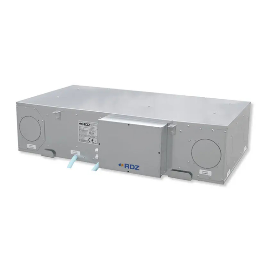
- Page 1 Air Handling Units Unità Trattamento Aria CHR 100 Mechanical ventilation with heat recovery appliance Ventilazione meccanica con sistema di recupero di calore TECHNICAL / INSTALLATION MANUAL MANUALE TECNICO / INSTALLAZIONE...
-
Page 3: Avvertenze Per La Sicurezza
SAFETY WARNINGS - AVVERTENZE PER LA SICUREZZA Read this manual carefully before installing and/or using the Le g g e re co n at te n z i o n e q u e s to l i b re t to p r i m a equipment and keep it in an accessible place. -
Page 4: Avvertenze Generali
GENERAL WARNINGS - AVVERTENZE GENERALI • If, after having unpacked the equipment, any anomaly is noted, • Se dopo aver disimballato l’apparecchiatura si nota una do not use the equipment and contact an Assistance Centre qualsiasi anomalia non utilizzare l’apparecchiatura e rivolgersi authorised by the manufacturer. -
Page 5: Table Of Contents
GENERAL OVERVIEW PANORAMICA GENERALE Description Descrizione Features And General Notes Caratteristiche e Note Generali Models And Accessories Modelli e Accessori CHR 100 Package Content Contenuto Imballo CHR 100 CHR 100 Components Componenti CHR 100 INSTALLAZIONE INSTALLATION Aerolics System Rete Aeraulica... -
Page 6: Operazioni Preliminari
PRELIMINARY OPERATIONS - OPERAZIONI PRELIMINARI TESTING, TRANSPORT AND UNPACKAGING ISPEZIONE, TRASPORTO E DISIMBALLO Upon receipt, check immediately that the packaging is intact: All’atto del ricevimento verificare immediatamente l’integrità the machine has left the factory in perfect working order and any dell’imballo: la macchina ha lasciato la fabbrica in perfetto stato, damage must be notified to the carrier immediately and noted on eventuali danni dovranno essere immediatamente contestati... -
Page 7: Panoramica Generale
Wi (via ModBus). FEATURES AND GENERAL NOTES - CARATTERISTICHE E NOTE GENERALI The CHR 100 appliance is a key part of a whole house ventilation Il CHR 100 è un componente chiave del sistema di ventilazione system specifically designed to improve indoor air quality in della intera casa specificatamente progettato per migliorare dwellings. -
Page 8: Modelli E Accessori
Description - Descrizione Cod. Remote Control 7045561 Controllo Remoto Condensation drain kit 7045556 Kit scarico condensa PACKAGE CONTENT CHR 100 - CONTENUTO IMBALLO CHR 100 Cod. 7045510 Rif. Descriptions Descrizione CHR 100 CHR 100 Flanged Spigots Manicotti Cartellati Installation / Technical Manual... -
Page 9: Componenti Chr 100
CHR 100 COMPONENTS - COMPONENTI CHR 100 Cod. 7045510 Rif. Descriptions Descrizione Supply fan Ventilatore immissione Heat recuperator Recuperatore di calore Exhaust fan Ventilatore espulsione Air filters: G3 prefilter + M5 filter Filtri aria esterna: Prefiltro G3 + Filtro M5... -
Page 10: Installazione
INSTALLATION - INSTALLAZIONE AERAULIC SYSTEM RETE AERAULICA CHOICE OF POSITION AND INSTALLATION OF SPIGOTS SCELTA POSIZIONE E INSTALLAZIONE MANICOTTI IFresh air intake from outside / Presa Aria fresca dall’esterno Supply fresh air to rooms / Immissione aria in ambiente Extract stale air from rooms / Ripresa aria viziata dalle stanze Exhaust stale air to outside / Espulsione aria viziata verso l’esterno Flanged Spigots on the long side Manicotti cartellati sul lato lungo... - Page 11 Additionally, both ducts al fine di rispettare i regolamenti edilizi. connecting the CHR 100 to outside must be insulated when Usare sempre gli isolamenti sulle linee di Estrazione-Espulsione passing through heated areas to avoid condensation forming on aria esterna e Immissione aria ambiente quando attraversano the outside of the ducts.
- Page 12 Inlet fresh air from outside / Presa Aria fresca dall’esterno Extract stale air from rooms / Ripresa aria viziata dalle stanze Supply fresh air to rooms / Immissione aria in ambiente Exhaust stale air to outside / Espulsione aria viziata verso l’esterno Inlet fresh air from outside Supply fresh air to rooms Presa Aria fresca dall’esterno...
- Page 13 Positioning indications & Minimum space allowanceses Indicazioni di posizionamento & Distanze minime di rispetto HORIZONTAL POSITIONING POSIZIONAMENTO ORIZZONTALE ≥ 60 cm Exhaust Espulsione Inlet Exhaust Immissione Espulsione ≥ 60 cm Inlet Immissione Exhaust Inlet INSIDE OUTSIDE Immissione Espulsione INTERNO ESTERNO VERTICAL POSITIONING POSIZIONAMENTO VERTICALE Inlet...
-
Page 14: Posizionamento E Fissaggio A Soffitto
POSITIONING AND FIXING TO THE CEILING POSIZIONAMENTO E FISSAGGIO A SOFFITTO CAUTION ATTENZIONE • Installation and maintenance must be carried out by • L’installazione e la manutenzione vanno eseguiti solo qualified personnel only. Throughout installation, make sure da personale qualificato. Durante tutte le procedure di that the equipment is not connected to the electrical mains. - Page 15 ø8mm Rubber mounts Gommino antivibrante Fixing to ceiling Washer Rondella Fissaggio a so tto min. 50 cm Trap door Botola d’ispezione...
-
Page 16: Collegamenti Idraulici
Scarico NON in salita! ADDITIONAL NOTES FOR RDZ DRAIN KIT INSTALLATION NOTE AGGIUNTIVE PER INSTALLAZIONE KIT SCARICO RDZ • Gently insert the siphon on the CHR exhaust pipe using the provided • Inserire delicatamente il sifone sul tubo di scarico CHR usando adapter. - Page 17 CONDENSATION DRAIN KIT cod. 7045556 KIT SCARICO CONDENSA Summer drain (not expected, must be plugged) Scarico estivo (non previsto, da tappare) Winter drain Scarico invernale ≥ 3 cm ≥3% Discharge NOT in ascent! Scarico NON in salita!
-
Page 18: Collegamenti Elettrici
ELECTRICAL CONNECTIONS - COLLEGAMENTI ELETTRICI OVERVIEW OF THE ELECTRONIC BOARD UNIT PANORAMICA SCHEDA ELETTRONICA A BORDO Descriptions Descrizione CAN port porta CAN RS-485 MODBUS master/slave port porta RS-485 MODBUS master/slave (can be configured with the UNI-PRO 3 development (configurabile con l’ambiente di sviluppo UNI-PRO 3) environment) INTRABUS port (RS-485 MODBUS master/slave by connecting porta INTRABUS (RS-485 MODBUS master/slave collegando... - Page 19 Descriptions Descrizione signal - CAN port segnale - porta CAN signal + CAN port segnale + porta CAN signal - RS-485 MODBUS master/slave port segnale - porta RS-485 MODBUS master/slave signal + RS-485 MODBUS master/slave port segnale + porta RS-485 MODBUS master/slave GND reference (GND) riferimento (GND) INTRABUS port data...
- Page 20 INSTALLATION INSTRUCTIONS INDICAZIONI DI INSTALLAZIONE The unit must be connected to a disconnected, earthed L’unità deve essere collegata ad una presa di power socket. The electrical system must be protected against corrente sezionata provvista di terra. L’impianto elettrico di overloads, short circuits and direct and indirect contacts and alimentazione deve essere protetto contro i sovraccarichi, i comply with the laws and regulations in force in the country of cortocircuiti, i contatti diretti ed indiretti, conformemente...
- Page 21 POWER SUPPLY ALIMENTAZIONE Connect the 3 terminals with Ø 1 mm cable: Portare e collegare i 3 morsetti con cavo Ø 1 mm phase (F) , neutral (N), ground fase (F) , neutro (N), terra 3 X Ø 1 mm NEUTRAL - NEUTRO PHASE - FASE GROUND - TERRA...
- Page 22 DIGITAL CONSENTS / COMANDI DIGITALI DIGITAL CONSENTS COMANDI DIGITALI DIGITAL OUTPUT USCITE DIGITALI (max 5 A) DEHUMIDIFIER DEUMIDIFICATORE (max 5 A) GENERAL ALARM ALLARME GENERALE (max 16 A) PUMP CONSENT COMANDO POMPA DIGITAL INPUT INGRESSI DIGITALI BOOST BOOST 230 V SEASON STAGIONE 230 V...
- Page 23 INSTALLATION WITHOUT REMOTE CONTROL INSTALLAZIONE SENZA CONTROLLO REMOTO DIRTY FILTERS ALARM VISUAL SIGNALER SEGNALATORE VISIVO ALLARME FILTRI SPORCHI In the case of installation without any remote control the signaling Nel caso di installazione senza nessun controllo remoto of the dirty filters alarm will occur by turning on the button installed la segnalazione dell’...
- Page 24 REMOTE CONTROL CONTROLLO REMOTO CAN- CAN+ +12 Vdc brown-marrone VAC+ white-bianco VAC- yellow-giallo CAN+ green-verde CAN- CHR 100 Remote Control Controllo Remoto WI UNIT CONTROLLER CONTROLLO CON CENTRALINA “WI” 2 x 0,5 mm modbus serial card 1 CHR 100 WI-SA...
-
Page 25: Panoramica Impianto
OVERVIEW OF THE SYSTEM - PANORAMICA IMPIANTO It is recommended to use a silencer in the supply and Si consiglia di prevedere un silenziatore sul canale di discharge ducts. mandata agli ambienti e espulsione verso l’esterno. -
Page 26: Funzionamento
FUNCTIONING - FUNZIONAMENTO Inlet fresh air from outside / Presa Aria fresca dall’esterno Extract stale air from rooms / Ripresa aria viziata dalle stanze Supply fresh air to rooms / Immissione aria in ambiente Exhaust stale air to outside / Espulsione aria viziata verso l’esterno Inlet-Supply Air Flow - Flusso Aria Ingresso-Immissione Exhaust Fan- Ventilatore di Espulsione Extract-Exhaust Air Flow - Flusso Aria Estrazione-Espulsione... - Page 27 DEHUMIDIFICATION / INTEGRATION DEUMIDIFICAZIONE / INTEGRAZIONE In the case of air treatment in Dehumidification / Integration, set Nel caso di trattamento aria in Deumidificazione/Integrazione the desired flow rates for both fans (Inlet and Exhaust) through impostare le portate desiderate per entrambi i ventilatori the dedicated parameters.
- Page 28 FREE-COOLING FREE-COOLING This model is supplied with motorized damper. If Free-Cooling Questo modello è fornito con una serranda motorizzata is ON, the fresh air from outside is not pre-heated in the heat attivabile automaticamente. Quando la funzionalità di Free recovery unit from the expulsion air. Cooling è...
-
Page 29: Manutenzione
Dopo un ciclo di 3 pulizie consecutive i filtri devono essere Contact RDZ to purchase new filters. sostituiti. Contattare RDZ per l’acquisto dei nuovi filtri. To clean or replace the filters remove the detachable plates located Per pulire o sostituire i filtri, rimuovere i relativi coperchi situati on the bottom of the unit. - Page 30 CLEANING THE EXCHANGER PULIZIA SCAMBIATORE Warning: the heat exchanger have to be cleaned every 2 years by Attenzione! La pulizia dello scambiatore di calore va effettuata removing the bottom panel from the unit. ogni due anni e avviene rimuovendo il pannello inferiore dell’ unità.
- Page 31 2 - EXTRAORDINARY MAINTENANCE / MANUTENZIONE STRAORDINARIA REMOVING THE FAN RIMOZIONE VENTILATORE Caution! To replace the fan you must remove the lower panel. Attenzione! La sostituzione del ventilatore avviene rimuovendo il pannello inferiore. Unscrew all the screws that block the bottom panel of the unit and remove it by lowering it downwards.
-
Page 32: Dati Tecnici E Prestazioni
TECHNICAL DATA AND PERFORMANCE - DATI TECNICI E PRESTAZIONI DIMENSIONS / DIMENSIONI Ø Ø 1017 1130 [mm] Overall machine dimensions Ingombri della macchina Height Altezza Width Larghezza Depth Profondità 1130 Weight Peso 30.5... -
Page 33: Etichetta Energetica
ENERGY LABEL / ETICHETTA ENERGETICA RDZ S.p.A. CHR 100 ENERGIA · · ΕΝΕΡΓΕΙΑ · ENERGIJA · ENERGY · ENERGIE 2016 FAK0CB002YZ.00 1254/2014... -
Page 34: Prestazioni Secondo (Ue) N. 1254/2014
Filter alarm reset via LED button installed on the machine q) Reset allarme filtri tramite pulsante Led installato a bordo macchina r) not applicable r) Non applicabile s) Recycling disassembly instruction - go to www.rdz.it s) Istruzioni per lo smaltimento -vai a www.rdz.it t) not applicable t) Non applicabile... -
Page 35: Dati Tecnici Scheda A Bordo Macchina
v) Annual electricity consumption (AEC) (in kWh electricity/a) v) consumo annuo di elettricità (AEC) (in kWh di elettricità/a); Control typology and CTRL factor Tipo di controllo e fattore CTRL Manual Clock Central demand Local demand Manuale Temporizzato Ambientale centralizzato Ambientale locale 0.95 0.85 0.65... - Page 36 Earthing methods for the control device Metodo di messa a terra del None nessuno dispositivo di comando: Rated impulse-withstand voltage 4 KV Tensione impulsiva nominale Over-voltage category Categoria di sovratensione Software class and structure Classe e struttura del software 4 per sonde PTC, NTC o Pt 1000 4 for PTC, NTC or Pt 1000 probes (can be (configurabili anche per ingresso digitale a configured also for dry contact digital input)
-
Page 37: Prestazione Ventilatori
FAN PERFORMANCE / PRESTAZIONI VENTILATORI Operating Range Range di Funzionamento Renewal air ow rate [m /h] Portata aria rinnovo [m /h]... -
Page 38: Schema Elettrico
WIRING DIAGRAM - SCHEMA ELETTRICO PROBE GND - GND SONDE (black - nero) pink - rosa pink - rosa brown marrone 30-05-2019 rev 03... - Page 40 FAG0CB007AB.01 05/2019...
Need help?
Do you have a question about the CHR 100 and is the answer not in the manual?
Questions and answers