Table of Contents

Subscribe to Our Youtube Channel
Related Manuals for RDZ CHR 200-FC


Summary of Contents for RDZ CHR 200-FC
- Page 1 Air Handling Units Unità Trattamento Aria CHR 200-FC Mechanical ventilation with heat recovery appliance Ventilazione meccanica con sistema di recupero di calore TECHNICAL / INSTALLATION MANUAL MANUALE TECNICO / INSTALLAZIONE...
-
Page 3: Avvertenze Per La Sicurezza
SAFETY WARNINGS - AVVERTENZE PER LA SICUREZZA Read this manual carefully before installing and/or using the Le g g e re co n at te n z i o n e q u e s to l i b re t to p r i m a equipment and keep it in an accessible place. -
Page 4: Avvertenze Generali
GENERAL WARNINGS - AVVERTENZE GENERALI • If, after having unpacked the equipment, any anomaly is noted, • Se dopo aver disimballato l’apparecchiatura si nota una do not use the equipment and contact an Assistance Centre qualsiasi anomalia non utilizzare l’apparecchiatura e rivolgersi authorised by the manufacturer. -
Page 5: Table Of Contents
SMALTIMENTO PRELIMINARY OPERATIONS OPERAZIONI PRELIMINARI GENERAL OVERVIEW PANORAMICA GENERALE Description Descrizione Features And General Notes Caratteristiche e Note Generali CHR 200-FC Package Content Contenuto Imballo CHR 200-FC Complements Complementi CHR 200-FC Components Componenti CHR 200-FC INSTALLAZIONE INSTALLATION Aerolics System Rete Aeraulica... -
Page 6: Operazioni Preliminari
PRELIMINARY OPERATIONS - OPERAZIONI PRELIMINARI TESTING, TRANSPORT AND UNPACKAGING ISPEZIONE, TRASPORTO E DISIMBALLO Upon receipt, check immediately that the packaging is intact: All’atto del ricevimento verificare immediatamente l’integrità the machine has left the factory in perfect working order and any dell’imballo: la macchina ha lasciato la fabbrica in perfetto stato, damage must be notified to the carrier immediately and noted on eventuali danni dovranno essere immediatamente contestati... -
Page 7: Panoramica Generale
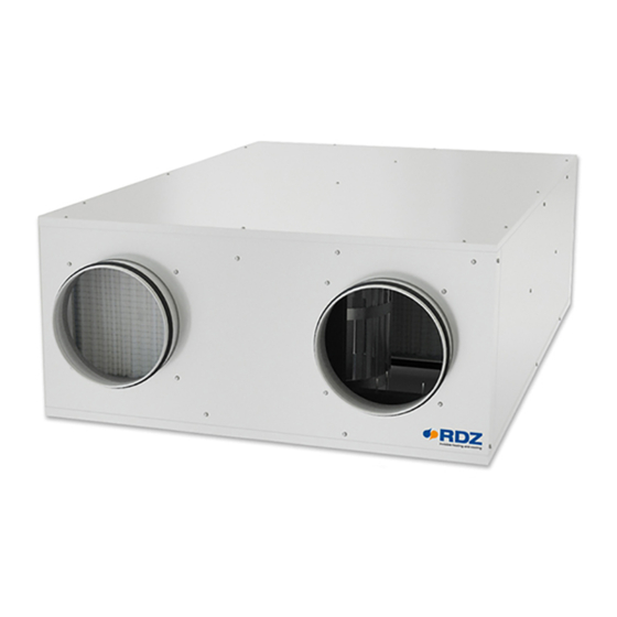
• Peso 32.5 kg FEATURES AND GENERAL NOTES - CARATTERISTICHE E NOTE GENERALI The CHR 200-FC appliance is a key part of a whole house ventilation Il CHR 200-FC è un componente chiave del sistema di system specifically designed to improve indoor air quality in ventilazione della intera casa specificatamente progettato per dwellings. -
Page 8: Descrizione
SIFOWALL Condensate drain kit with casing, designed for wall installation. It can be used in combination with RDZ air handling units, and it is suitable for Ø 20-32 mm piping. The external shell can be adjusted considering the thickness of the wall. Washable Internal Cartridge. -
Page 9: Componenti Chr 200-Fc
CHR 200-FC COMPONENTS - COMPONENTI CHR 200-FC Rif. Descriptions Descrizione Supply Air fan Ventilatore di Immissione Aria Heat recuperator Recuperatore di calore Exhaust Air fan Ventilatore di Espulsione Aria Air filters: Filtri aria esterna: ISO Coarse 40% (G2) Prefilter +... -
Page 10: Installazione
Additionally, both ducts al fine di rispettare i regolamenti edilizi. connecting the CHR 200-FC to outside must be insulated when Usare sempre gli isolamenti sulle linee di Estrazione-Espulsione passing through heated areas to avoid condensation forming on aria esterna e Immissione aria ambiente quando attraversano the outside of the ducts. - Page 11 Fresh Air Inlet Exhaust Air Stale Air Extraction Supply Air Ingresso Aria Esterna Espulsione aria Estrazione aria viziata Immissione Aria Fresh Air Inlet Supply Air Ingresso Aria Esterna Immissione Aria Outside Inside Inside Esterno Interno Interno Stale Air Extraction Exhaust Air Estrazione aria viziata Espulsione aria Inside...
- Page 12 Positioning indications & Minimum space allowanceses Indicazioni di posizionamento & Distanze minime di rispetto HORIZONTAL POSITIONING POSIZIONAMENTO ORIZZONTALE ≥ 60 cm Exhaust Espulsione Inlet Exhaust Immissione Espulsione ≥ 60 cm Inlet Immissione Exhaust Inlet INSIDE OUTSIDE Immissione Espulsione INTERNO ESTERNO VERTICAL POSITIONING POSIZIONAMENTO VERTICALE Inlet...
-
Page 13: Posizionamento E Fissaggio A Soffitto
POSITIONING AND FIXING TO THE CEILING POSIZIONAMENTO E FISSAGGIO A SOFFITTO CAUTION ATTENZIONE • Installation and maintenance must be carried out by • L’installazione e la manutenzione vanno eseguiti solo qualified personnel only. Throughout installation, make sure da personale qualificato. Durante tutte le procedure di that the equipment is not connected to the electrical mains. - Page 14 ø8mm Rubber mounts Gommino antivibrante Fixing to ceiling Washer Rondella Fissaggio a so tto min. 50 cm Trap door Botola d’ispezione...
-
Page 15: Collegamenti Idraulici
It is necessary to make the siphon on drain line using È necessario realizzare il sifone sulla linea di scarico and choosing, as required, from the available RDZ utilizzando e scegliendo, in base alle esigenze, fra i condensate drain kits (SIFOWALL / CONDENSATE kit di scarico condensa RDZ disponibili (SIFOWALL DRAIN KIT). - Page 16 SIFOWALL Cod. Condensate drain kit with casing, designed for wall installation. It can be used in combination with RDZ air handling units, and it is suitable for Ø 20-32 mm piping. The external shell can be adjusted considering the thickness of the wall. Washable Internal Cartridge. For information see the dedicated technical sheet.
- Page 17 RDZ air handling units. 3600401 Kit di scarico condensa composto da sifone con membrana in silicone, tubo e raccordo, da utilizzare in abbinamento alle unità di trattamento dell’aria RDZ. NOTE AGGIUNTIVE PER INSTALLAZIONE KIT SCARICO RDZ ADDITIONAL NOTES FOR RDZ DRAIN KIT INSTALLATION •...
-
Page 18: Collegamenti Elettrici
ELECTRICAL CONNECTIONS - COLLEGAMENTI ELETTRICI OVERVIEW OF THE ELECTRONIC BOARD UNIT PANORAMICA SCHEDA ELETTRONICA A BORDO Descriptions Descrizione CAN port porta CAN RS-485 MODBUS master/slave port porta RS-485 MODBUS master/slave (can be configured with the UNI-PRO 3 development (configurabile con l’ambiente di sviluppo UNI-PRO 3) environment) INTRABUS port (RS-485 MODBUS master/slave by connecting porta INTRABUS (RS-485 MODBUS master/slave collegando... - Page 19 Descriptions Descrizione signal - CAN port segnale - porta CAN signal + CAN port segnale + porta CAN signal - RS-485 MODBUS master/slave port segnale - porta RS-485 MODBUS master/slave signal + RS-485 MODBUS master/slave port segnale + porta RS-485 MODBUS master/slave GND reference (GND) riferimento (GND) INTRABUS port data...
- Page 20 INSTALLATION INSTRUCTIONS INDICAZIONI DI INSTALLAZIONE The unit must be connected to a disconnected, earthed L’unità deve essere collegata ad una presa di power socket. The electrical system must be protected against corrente sezionata provvista di terra. L’impianto elettrico di overloads, short circuits and direct and indirect contacts and alimentazione deve essere protetto contro i sovraccarichi, i comply with the laws and regulations in force in the country of cortocircuiti, i contatti diretti ed indiretti, conformemente...
- Page 21 POWER SUPPLY ALIMENTAZIONE Connect the 3 terminals with Ø 1 mm cable: Portare e collegare i 3 morsetti con cavo Ø 1 mm phase (F) , neutral (N), ground fase (F) , neutro (N), terra 3 X Ø 1 mm NEUTRAL - NEUTRO PHASE - FASE GROUND - TERRA...
- Page 22 DIGITAL CONSENTS / COMANDI DIGITALI DIGITAL CONSENTS COMANDI DIGITALI DIGITAL OUTPUT USCITE DIGITALI (max 5 A) DEHUMIDIFIER DEUMIDIFICATORE (max 5 A) GENERAL ALARM ALLARME GENERALE (max 16 A) PUMP CONSENT COMANDO POMPA DIGITAL INPUT INGRESSI DIGITALI BOOST BOOST 230 V SEASON STAGIONE 230 V...
- Page 23 3 SPEED SWITCH SELETTORE A 3 VELOCITA’ 3 SPEED SWITCH COMMUTATORE 3 VELOCITA’ BOOST BOOST 230 V black - nero pink - rosa ECO / DEHUM. REQUEST grey - grigio RICHIESTA ECONOMY / DEUM. CAN- CAN+ VENTILATION REQUEST 12Vdc RICHIESTA RINNOVO black - nero orange - arancione 0-10V...
- Page 24 INSTALLATION WITHOUT REMOTE CONTROL INSTALLAZIONE SENZA CONTROLLO REMOTO DIRTY FILTERS ALARM VISUAL SIGNALER SEGNALATORE VISIVO ALLARME FILTRI SPORCHI Failure to clean and / or replace the air lters may result in the incorrect discharge of the condensate with possible risk of it dripping. La mancata pulizia e/o sostituzione dei ltri aria può...
- Page 25 CAN- CAN+ +12 Vdc brown-marrone VAC+ white-bianco VAC- yellow-giallo CAN+ green-verde CAN- CHR 200-FC WI UNIT CONTROLLER CONTROLLO CON CENTRALINA “WI” SEASON STAGIONE 230 V 2 x 0,5 mm modbus serial card 1 CHR 200-FC WI-SA in MODBUS mode the season input is used to select the second machine (address-10)
-
Page 26: Funzionamento
FUNCTIONING - FUNZIONAMENTO Fresh Air Inlet Exhaust Air Stale Air Extraction Supply Air Ingresso Aria Esterna Espulsione aria Estrazione aria viziata Immissione Aria Ø Ø Ø Ø coarse coarse Inlet-Supply Air Flow - Flusso Aria Ingresso-Immissione Exhaust Fan- Ventilatore di Espulsione Extract-Exhaust Air Flow - Flusso Aria Estrazione-Espulsione Air Filters - Filtri Aria Supply Fan - Ventilatore di Immissione... - Page 27 DEHUMIDIFICATION / INTEGRATION DEUMIDIFICAZIONE / INTEGRAZIONE In the case of air treatment in Dehumidification / Integration, set Nel caso di trattamento aria in Deumidificazione/Integrazione the desired flow rates for both fans (Inlet and Exhaust) through impostare le portate desiderate per entrambi i ventilatori the dedicated parameters.
- Page 28 FREE-COOLING FREE-COOLING This model is supplied with motorized damper. If Free-Cooling Questo modello è fornito con una serranda motorizzata is ON, the fresh air from outside is not pre-heated in the heat attivabile automaticamente. Quando la funzionalità di Free recovery unit from the expulsion air. Cooling è...
-
Page 29: Manutenzione
Vacuum cleaning is allowed. After 3 consecutive cleaning filtri a bordo macchina). È consentito pulire i filtri a vapore. operations, filters must be replaced. Contact RDZ to purchase new Dopo un ciclo di 3 pulizie consecutive i filtri devono essere filters. - Page 30 CLEANING THE EXCHANGER PULIZIA SCAMBIATORE Warning: the heat exchanger have to be cleaned every 2 years by Attenzione! La pulizia dello scambiatore di calore va effettuata removing the bottom panel from the unit. ogni due anni e avviene rimuovendo il pannello inferiore dell’ unità.
- Page 31 2 - EXTRAORDINARY MAINTENANCE / MANUTENZIONE STRAORDINARIA REMOVING THE FAN RIMOZIONE VENTILATORE Caution! To replace the fan you must remove the lower panel. Attenzione! La sostituzione del ventilatore avviene rimuovendo il pannello inferiore. OFF! x 18 Disconnect and remove the power supply and fan control cables from the electrical panel (see wiring diagram).
-
Page 32: Dati Tecnici E Prestazioni
TECHNICAL DATA AND PERFORMANCE - DATI TECNICI E PRESTAZIONI DIMENSIONS / DIMENSIONI Ø 150 Ø 150 1040 [mm] 1124 Overall machine dimensions Ingombri della macchina Height Altezza Width Larghezza Depth Profondità 1124 Weight Peso 32.5 • Nominal air flow 200 m³/h with 200 Pa •... -
Page 33: Prestazioni Secondo (Ue) N. 1254/2014
Filter alarm reset via LED button installed on the machine q) Reset allarme filtri tramite pulsante Led installato a bordo macchina r) not applicable r) Non applicabile s) Recycling disassembly instruction - go to www.rdz.it s) Istruzioni per lo smaltimento -vai a www.rdz.it t) not applicable t) Non applicabile... - Page 34 Cold - Freddo 8745 8787 8872 9040 Average - Temperato 4470 4492 4535 4621 Warm - Caldo 2021 2031 2051 2090 ENERGY LABEL ETICHETTA ENERGETICA RDZ S.p.A. CHR 200 ENERGIA · · ΕΝΕΡΓΕΙΑ · ENERGIJA · ENERGY · ENERGIE 2016 FAK0CB003YZ.00 1254/2014...
-
Page 35: Prestazioni Dei Ventilatori
PERFORMANCE OF THE FANS / PRESTAZIONI DEI VENTILATORI Inlet Fan - Ventilatore Immissione Electric Consumption Consumo Elettrico 68 W 90 W 75 W 96 W 79 W 100 W 83 W Air ow - Portata aria (m /h) Exhaust Fan - Ventilatore Espulsione Electric Consumption Consumo Elettrico 68 W... -
Page 36: Dati Tecnici Scheda A Bordo Macchina
TECHNICAL DATA OF THE UNIT ELECTRONIC BOARD / DATI TECNICI SCHEDA A BORDO MACCHINA Category of heat and fire resistance Categoria di resistenza al calore e al fuoco Measurements 142.0 x 110.0 x 31.0 mm Dimensioni morsettiere a vite per conduttori fino a 2,5 Connection method screw terminal blocks for wires up to 2.5 mm²... - Page 37 0-5 V transducers Input resistance: ≥ 10KΩ Resistenza di ingresso: ≥ 10 KΩ Trasduttori 0-5 V: Resolution: 0.01 V. Risoluzione: 0,01 V. 0-10 V transducers Input resistance: ≤ 200 Ω Resistenza di ingresso: ≤ 200 Ω Trasduttori 0-10 V Resolution: 0.01 mA. Risoluzione: 0,01 mA.
-
Page 38: Schemi Elettrici
WIRING DIAGRAMS - SCHEMI ELETTRICI PROBE GND - GND SONDE (black - nero) pink - rosa pink - rosa brown marrone 28-06-2019 - CHR 200-FC - rev 01... - Page 39 CHIMNEY FUNCTION WIRING DIAGRAM SCHEMA ELETTRICO FUNZIONE CAMINO NEUTRAL - NEUTRO PHASE - FASE CAN - POWER CAN + 230 V - 50 Hz RENEWAL REQUEST INPUT - INGRESSO RICHIESTA RINNOVO MODBUS B - RENEWAL REQUEST INPUT - INGRESSO RICHIESTA RINNOVO MODBUS A + black - nero...
- Page 44 FAG0CB009AB.04 03/2021...
Need help?
Do you have a question about the CHR 200-FC and is the answer not in the manual?
Questions and answers