ETC echoflex ELEDR Configuration Manual
Power load controller
Hide thumbs
Also See for echoflex ELEDR:
- Installation manual (8 pages) ,
- Configuration manual (22 pages)

Related Manuals for ETC echoflex ELEDR


Summary of Contents for ETC echoflex ELEDR
- Page 1 Power Load Controller Models: ELEDR and ELEDRH Configuration Guide Part Number: 8189M2430 Rev.A Released: 2022-10...
- Page 2 To view a list of Echoflex trademarks and patents, go to echoflexsolutions.com/ip. All other trademarks, both marked and not marked, are the property of their respective owners. Echoflex intends this document, whether printed or electronic, to be provided in its entirety.
-
Page 3: Table Of Contents
Table of Contents Introduction Features Document Conventions Help from Technical Services Configuration Options Simple Tap Instructions Radio Communications Repeater Function Status Message Radio Range Confirmation Near-Cross Technology Switch Operation Timed Switches Occupancy-Based Lighting Applications Occupancy Sensor Auto-OFF Timer Save State Grace Timer Photo Inhibit Dual Technology Occupancy Sensors Occupancy Sensors Only... - Page 4 Hospitality Applications Daylight Harvesting Applications Daylighting Control Override Open Loop Control Controller Presets User Interface Power LED and Learn LED Learn Button Remote Linking Solution Clear Button LED Display Blink Indications Device Count Codes Linking Activities Compliance FCC Compliance ISED Compliance Conformité...
-
Page 5: Introduction
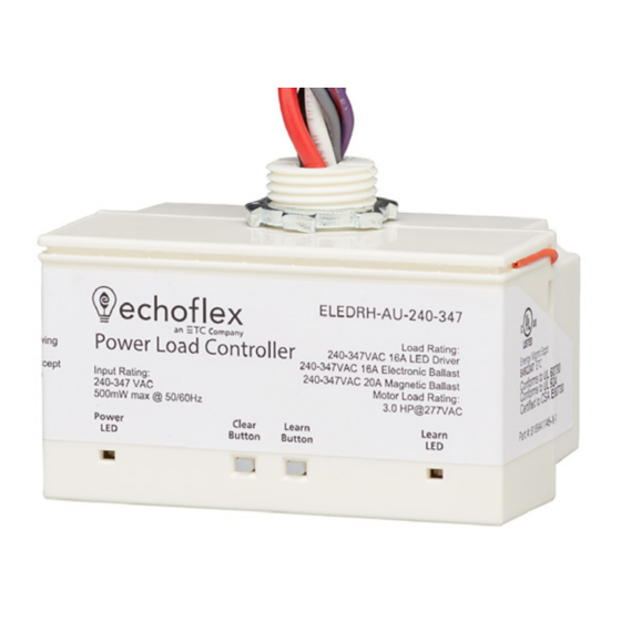
Introduction The Power Load Controller is a wireless lighting controller for electronic ballasts and LED drivers. It also provides a motor load specification to deliver process control for circuit or fan/curtain control applications, eliminating long wire runs. With the ELEDR or ELEDRH, high- voltage model, you can integrate lighting and automation control into one distributed wireless device. -
Page 6: Document Conventions
Document Conventions Echoflex's user documentation is designed for print or electronic use. Cross-references highlighted in this document are links to the referenced section of the guide. Configuration parameters are emphasized in italics. Switch actions (ON/OFF) and dimmer events (lights ON/OFF) are emphasized in ALL CAPS. Buttons are emphasized in [Bold Bracket]. This document uses the following conventions to draw your attention to important information. -
Page 7: Configuration Options
Configuration Options The controller provides lighting control using input received from compatible Echoflex devices. It operates based on: Ambient light levels monitored by a wireless photo sensor • Occupancy state monitored by a wireless occupancy sensor • Switch action from a wireless wall or keycard switch •... -
Page 8: Radio Range Confirmation
Radio Range Confirmation Echoflex sensors that are equipped with patented Range Confirmation technology work with ELEDR(H) controllers to facilitate optimal sensor placement. The Range Confirmation test is invoked at the sensor. It must be linked to the controller and during the test, any repeaters in the controller's vicinity must be disabled. -
Page 9: Occupancy-Based Lighting Applications
Occupancy-Based Lighting Applications When occupancy sensors linked to the controller do not detect motion, they send a vacancy message to the controller. After the occupancy auto-OFF timer expires, the controller turns the lights OFF or fades to a preset level. For information about coordinated control of a space, see Open-Plan Shared Occupancy on page Occupancy Sensor Auto-OFF Timer The occupancy auto-OFF timer is set to 15 minutes by default. -
Page 10: Photo Inhibit
Photo Inhibit The photo inhibit feature requires a linked photo sensor and an occupancy sensor with partial- ON enabled. See Occupancy Sensors and Partial-ON on page 1. When photo inhibit is enabled, the partial-ON feature is ignored when the natural light level measured by the photo sensor is above the lights ON set point. -
Page 11: Create A Shared Occupancy Space
A shared occupancy timer starts when a controller transitions from occupied to vacant. Controllers with the same shared occupancy ID that remain occupied will reset the shared occupancy timer of any controller reporting vacancy within the ID group. The vacant controllers will remain at the partial-OFF value until all controllers in the group report vacancy. -
Page 12: Hospitality Applications
Hospitality Applications Hospitality is a specific kind of occupancy-based control. When the controller is used in a hotel or dormitory setting, it is typically linked to a keycard switch station or to both an entry door sensor and an occupancy sensor. For example, when an occupant enters a room and inserts a key card into the keycard switch station an occupancy message is sent to linked controllers to power the room. -
Page 13: Open Loop Control
Open Loop Control Open loop daylighting becomes active when a photo sensor with a maximum detectable range of light greater than 2500 lux is linked to the controller. In open loop daylighting, the sensor monitors the natural light contribution and should be mounted so it is not affected by the controlled fixture's light output. -
Page 14: Controller Presets
Max. Output Min. Output Taps Light Response Set point Set point 2 taps 100% 3 blinks 3 taps 100% 4 blinks 4 taps 100% 5 blinks Sensor Range of > 11000 lux Max. Output Min. Output Taps Light Response Set point Set point 0 tap 1 blink... -
Page 15: User Interface
User Interface Note: Garibaldi Pro software is the ideal tool to set up your project and configure settings, or even to make edits if your project has been pre-commissioned. Garibaldi Pro is available for download at echoflexsolutions.com. Two buttons on the controller can be used to activate features and set specific configurations directly on the device. -
Page 16: Clear Button
Clear Button The [C lear] button can be used to reset the controller either to its pre-commissioned state or to its factory default state. To reset to pre-commissioned state: 1. Press and hold the [C lear] button until the red Power and green Learn LEDs start blinking. 2. -
Page 17: Blink Indications
Blink Indications The tables below describe the LED codes that identify linked devices and the LED indications that describe linking activities. Device Count Codes The following codes provide a visible report of the devices that are linked to the controller. The Power LED repeats a code of blinks that represent the type and number of linked devices. -
Page 18: Compliance
Compliance For complete regulatory compliance information, see the Echoflex Power Load Controller datasheet at echoflexsolutions.com. FCC Compliance Echoflex Power Load Controller (For any FCC matters): Echoflex Solutions, Inc. 3031 Pleasant View Road Middleton, WI 53562 +1 (608) 831-4116 echoflexsolutions.com This device complies with Part 15 of the FCC Rules. Operation is subject to the following two conditions: (1) this device may not cause harmful interference, and (2) this device must accept any interference received;... - Page 19 Compliance...
- Page 20 Corporate Headquarters n Middleton, WI, USA | +1 608 831 4116 echoflexsolutions.com | Email info@echoflexsolutions.com | Support service@echoflexsolutions.com ©2022 Echoflex Solutions, Inc. Trademark and patent info: echoflexsolutions.com/ip Product information and specifications subject to change. Echoflex intends this document to be provided in its entirety. 8189M2430 Rev A Released 2022-10...
Need help?
Do you have a question about the echoflex ELEDR and is the answer not in the manual?
Questions and answers