ETC Echoflex Elaho Installation Manual
0–10v controller–gen 2
Hide thumbs
Also See for Echoflex Elaho:
- Installation manual (13 pages) ,
- Installation manual (13 pages) ,
- Installation manual (13 pages)
Table of Contents
Advertisement
Quick Links
Echoflex Solutions Installation Guide
Elaho 0–10V Controller–Gen 2
Overview
The Elaho 0–10V Controller–Gen 2 provides fully-rated 20 A relays for
direct control of individual fixtures or zone power, and offers fully
isolated 0–10 V dimming control for compatible LED drivers and
fluorescent ballasts.
Two models are available:
Single Zone (ELD-G2)
•
Dual Zone (EDLD-G2)
•
The 0–10V Controller–Gen 2 controls lighting loads based on the
following:
Preset and Zone controls received from connected Elaho control
•
stations
Ambient light levels as monitored by Elaho Light Sensors
•
Occupancy state as monitored by Elaho Occupancy/Vacancy Sensors
•
Input from other Elaho control devices
•
Corporate Headquarters n Middleton, WI, USA | +1 608 831 4116
© 2024 Echoflex Solutions, Inc. | Trademark and patent info:
Web
echoflexsolutions.com
Third-party license agreement
change. Echoflex Solutions intends this document to be provided in its entirety.
8187M2102 Rev D Released 2024-03
| Email
info@echoflexsolutions.com
info: etcconnect.com/licenses
echoflexsolutions.com/ip
| Support
service@echoflexsolutions.com
| Product information and specifications subject to
Dual Zone
0–10 V model
shown
Advertisement
Table of Contents

Related Manuals for ETC Echoflex Elaho


Summary of Contents for ETC Echoflex Elaho
- Page 1 Echoflex Solutions Installation Guide Elaho 0–10V Controller–Gen 2 Overview The Elaho 0–10V Controller–Gen 2 provides fully-rated 20 A relays for direct control of individual fixtures or zone power, and offers fully isolated 0–10 V dimming control for compatible LED drivers and fluorescent ballasts. Dual Zone 0–10 V model shown...
-
Page 2: Custom Configuration
Echoflex Solutions Installation Guide 0–10V Controller–Gen 2 Custom Configuration This document guides you through the installation and local configuration of the 0–10V Controller–Gen 2. You can access advanced functionality using the ElahoAccess Mobile App. For more information, see the ElahoAccess integrated help system. ... - Page 3 Echoflex Solutions Installation Guide 0–10V Controller–Gen 2 Dual Zone model supports: Power input 120–277 VAC, 60 Hz • Load rating: • 20 A general purpose, tungsten, or resistive 16 A electronic ballast Note: The maximum load on the Dual Zone model can be split between the two relay outputs in any combination required for the installation, but cannot exceed the maximum load as specified above.
-
Page 4: Prepare For Installation
Echoflex Solutions Installation Guide 0–10V Controller–Gen 2 Note: This equipment has been tested and found to comply with the limits for a Class A digital device, pursuant to Part 15 of the FCC rules. These limits are designed to provide reasonable protection against harmful interference when the equipment is operated in a commercial environment. -
Page 5: Installation
Echoflex Solutions Installation Guide 0–10V Controller–Gen 2 Installation Installation should follow all local codes and standard electrical practices. Ensure that the junction box is clean and free of obstructions and that all wiring is installed correctly. WARNING: RISK OF ELECTRIC SHOCK! This device utilizes high voltage and should only be installed by a qualified installer or electrician. - Page 6 Echoflex Solutions Installation Guide 0–10V Controller–Gen 2 Connect EchoConnect The EchoConnect wire terminations are bound together and include a black wire (data -), a white wire (data +), and a green/yellow wire (ESD). Because EchoConnect is topology free, you can install the wires in any combination of bus, star, loop, or home-run.
- Page 7 Echoflex Solutions Installation Guide 0–10V Controller–Gen 2 Connect Power Input and Relay Output The power input and relay output wiring exits the 0–10V Controller–Gen 2 through the knockout mount on the enclosure. 1. Connect the power input wiring. a. Connect the white wire (14 AWG) to the incoming neutral wire from the breaker panel and the neutral wire of the lighting load.
- Page 8 Echoflex Solutions Installation Guide 0–10V Controller–Gen 2 Gray (-) Single Zone 0–10 V Dimming 0–10 V Ballast 1 Violet (+) Black 120–277 VAC Load 1 White Neutral White Black EchoConnect Green/Yellow Ground Gray (-) Dual Zone 0–10 V Dimming 0–10 V Ballast 1 Violet (+) Gray/White (-)
- Page 9 Echoflex Solutions Installation Guide 0–10V Controller–Gen 2 Connect 0–10V Dimming Output WARNING: RISK OF DEATH OR INJURY BY ELECTRIC SHOCK! 0–10V wiring may not be fully isolated from high- voltage AC power. Do not assume that 0–10V wiring is safe to touch, even when run as an NEC Class 2 signal. Have a licensed electrician test for AC voltage to ground before terminating any 0–10V control wiring to the device.
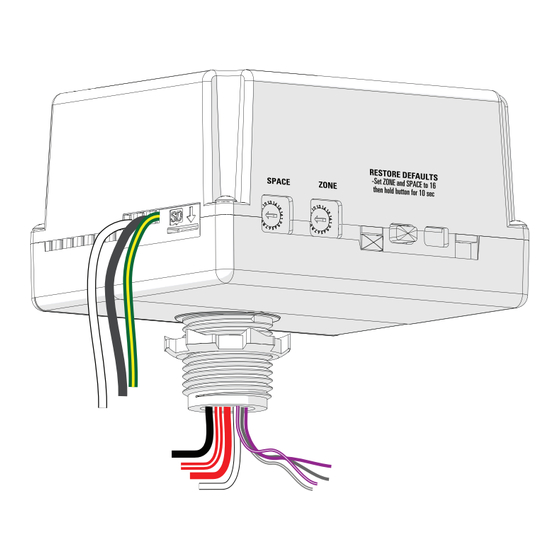
- Page 10 Echoflex Solutions Installation Guide 0–10V Controller–Gen 2 Assign Zones and Spaces You can assign zones and spaces using the two rotary switches on the side panel of the controller. The Dual Zone controller assigns two zones by using the Zone switch setting as the first zone assignment and then automatically assigning the next consecutive zone number for the second zone.
-
Page 11: Power Up And Test
Update Firmware If updated firmware is required, you can update the firmware on the 0– 10V Controller–Gen 2 by using ETC UpdaterAtor software and a microSD card. You can download UpdaterAtor from the ETC website at etcconnect.com. - Page 12 Echoflex Solutions Installation Guide 0–10V Controller–Gen 2 4. Insert the microSD card in the SD slot on the side of the 0–10V Controller–Gen 2 enclosure. An LED will illuminate amber in a triple-blink pattern while the • firmware is updating, and then will return to its previous state when the update is complete.
Need help?
Do you have a question about the Echoflex Elaho and is the answer not in the manual?
Questions and answers