
Related Manuals for iRay Technology Luna1012X


Summary of Contents for iRay Technology Luna1012X
- Page 1 Luna1012X Wireless Digital Flat Panel Detector User Manual Document Version: Document ID: 166-201-02 Release Date: 4/2/2022...
- Page 2 Thanks you for purchasing the Luna1012X (hereinafter referred to as Luna1012X) Digital Flat Panel Detector from iRay Technology Co., Ltd. (hereinafter referred to as iRay). This manual contains all the general information about the Luna1012X, which is intended to provide users with instructions on installation, use and maintenance.
- Page 3 Luna1012X User Manual To Customers For Your Safety To avoid personal injury or product damage, be sure to read the user manual and all accompanying information carefully and pay attention to all safety information before installing and using the detector.
- Page 4 Luna1012X User Manual To Customers This emphasizes or supplements important information about the main text. NOTE This symbol is used to indicate “please refer to accompanying documents attached to the CD disk”. REFERENCE Abbreviations Abbreviations Explanation Alternating Current Automatic Exposure Detection...
-
Page 5: Table Of Contents
Luna1012X User Manual Contents Contents TO CUSTOMERS ..........................I CONTENTS .............................IV 1 SAFETY INFORMATION ......................... 1 1.1 Product Symbols ............................1 1.1.1 Symbols on the Package Box .........................1 1.1.2 Symbols on the Product Label ........................1 1.2 Safety Precautions ............................3 1.2.1 Operation and Storage Environment ......................3... - Page 6 Luna1012X User Manual Contents 3.8 Component Description ..........................15 3.8.1 Detector ................................15 3.8.2 Battery Pack ..............................17 3.8.3 Battery Charger ............................17 3.8.4 Control Box ..............................18 3.8.5 Handle ................................19 3.8.6 Power Adapter ..............................19 3.9 Product Installation ...........................20 3.9.1 Attaching Battery to Detector ........................20 3.9.2 Installing the Battery into Battery Charger ....................
-
Page 7: Contents
Luna1012X User Manual Contents 6.2 Software Mode ............................43 6.2.1 Block Diagram ............................. 43 6.2.2 Workflow (PrepAcq) ............................44 6.2.3 Workflow (Prep+Acq) ..........................44 6.3 AED Mode ............................... 45 6.3.1 Inner Mode ..............................45 6.3.2 Freesync Mode .............................45 6.4 Calibration Template Generation ......................46 6.4.1 Generating HWPreOffset Template ......................46... -
Page 8: Safety Information
“Keep away from direct sunlight”. 1.1.2 Symbols on the Product Label The label in the figure below is only an example and does not represent the actual label. Please refer to the label on the detector host. Copyright © iRay Technology Co., Ltd. - Page 9 This symbol is used to represent the user manual for general nonionizing electromagnetic radiation. information. This product is not to be disposed This symbol is used to indicate the of with your residential or expiration date. 20XX-XX-XX commercial waste. Copyright © iRay Technology Co., Ltd.
-
Page 10: Safety Precautions
Do not turn on the power switch when there is condensation on the detector or any of its components or accessories. Ignoring this warning may result in an explosion, fire, or electric shock, which may result in personal injury, death, or substantial product damage. Copyright © iRay Technology Co., Ltd. -
Page 11: Equipment, Interface, Power Source, And Cables
Do not use any power source other than the one provided with this equipment. Otherwise, improper power connection may lead to fire or electric shock. Copyright © iRay Technology Co., Ltd. -
Page 12: Handling
Otherwise, it may result in fire or electric shock. For avoiding such contact, the disposable protective covers should be used to protect the equipment. Copyright © iRay Technology Co., Ltd. -
Page 13: Failure Handling
Do not immerse the battery in water or other liquids, keep it dry when using the battery. Do not use batteries not provided by iRay. Do not charge damaged batteries or charge batteries with damaged chargers. Copyright © iRay Technology Co., Ltd. -
Page 14: Maintenance And Inspection
until the condensation evaporates before performing an exposure. If condensation occurs during the use of the equipment, the images captured may suffer from quality problems. When an air-conditioner is used, be sure to Copyright © iRay Technology Co., Ltd. - Page 15 Wipe it with a cloth slightly damped with a neutral detergent. Do not use solvents such as alcohol, thinner, benzene, acid and base. Doing so may damage the surface of the equipment. It’s recommended to use a waterproof non-woven cover as the isolated layer between detector and the blooding patient. Copyright © iRay Technology Co., Ltd.
-
Page 16: Regulatory Information
X-ray equipment for radiography and radioscopy (Edition1.2) Medical electrical equipment-Part1-6: General requirements for basic safety IEC 60601-1-6-2013 and essential performance-collateral standard: Usability (Edition3.1) Guidance and Manufacturer’s Declaration For EMC 2.3.1 EMI Compliance Table Emissions Copyright © iRay Technology Co., Ltd. -
Page 17: Ems Compliance Table
FM, ± 5kHz deviation, 1kHz sine, 28V/m 704-787 Pulse modulation 217Hz, 9V/m 800-960 Pulse modulation 18Hz, 28V/m 1720 1845 1700-1990 Pulse modulation 217Hz, 28V/m 1970 2450 2400-2570 Pulse modulation 217Hz, 28V/m 5240 5500 5100-5800 Pulse modulation 217Hz, 9V/m 5785 Copyright © iRay Technology Co., Ltd. -
Page 18: Battery Safety Standards
This device must accept any interference received, including interference that may cause undesired operation. This equipment has been tested and found to comply with the limits for a Class B digital device, pursuant to part 15 of Copyright © iRay Technology Co., Ltd. -
Page 19: Radio Frequency (Rf) Energy
SAR compliance for body-worn operation is based on a separation distance of 0 mm between the unit and the human body. Carry this device at least 0 mm away from your body to ensure RF exposure level compliant or lower to the reported level. Copyright © iRay Technology Co., Ltd. -
Page 20: Product Introduction
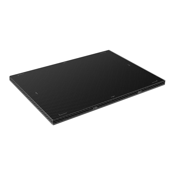
3152×2502 with 100um pixel pitch. It renders high quality radiographic images with the CSI (Caesium Iodide) scintillator which is direct deposit. Since Luna1012X supports multiple trigger modes, it can satisfy both of the general DR system and retrofit DR system. Scope of Application It is suitable for providing digital X-ray imaging for DR system to provide general radiographic diagnosis for human anatomy, but not intended for mammography or dental applications. -
Page 21: Essential Performance
Check the list below to verify that all the items have been included. Contact your iRay dealer if anything is missing or damaged. Item Qty. (unit: piece) Remarks Luna1012X Detector Power adapter Battery pack Battery charger Default Gigabit Ethernet cable AC power cable Control box Copyright © iRay Technology Co., Ltd. -
Page 22: Component Description
B C D Status indicator Power button Link indicator 24V DC input interface Power indicator Detector label The whole main unit encloser is defined as applied part that is accessible to the patient. NOTE Copyright © iRay Technology Co., Ltd. - Page 23 Shutdown: when the detector is turned on, you can press the button and hold for 4 seconds to turn off the detector. Reset: press the button for 8 seconds to reset the internal control core piece. Copyright © iRay Technology Co., Ltd.
-
Page 24: Battery Pack
3.8.3 Battery Charger Power indicator 5-pin Battery connector Charging indicator Anti-drop latch Charge full indicator Battery removal position 8-pin Battery connector AC power interface LED Indicators Indicator Status Operating Status All off No power input Copyright © iRay Technology Co., Ltd. -
Page 25: Control Box
Two or more battery charging at the same time is prohibited, if inserted at the same time, the charger will automatically stop working. NOTE 3.8.4 Control Box Power interface Switch Reserved 19-pin interface LAN interface Copyright © iRay Technology Co., Ltd. -
Page 26: Handle
U8V 093768 0016. The ports defined as bellow: Pin1 Pin2 Pin3 Pin4 Definition Voltage Range Rated Current DC Power Negative 0~0.5V 0~0.42A DC Power Positive 23~25V 0~0.42A DC Power Positive 23~25V 0~0.42A DC Power Negative 0~0.5V 0~0.42A Copyright © iRay Technology Co., Ltd. -
Page 27: Product Installation
Slide the battery lock lever in the direction shown until fully locked. 3.9.2 Installing the Battery into Battery Charger Insert battery into battery charger in the direction shown right. Press the battery down into the battery compartment. Copyright © iRay Technology Co., Ltd. - Page 28 Luna1012X User Manual Product Introduction After the battery if fully charged, unload the battery from the battery charger. Copyright © iRay Technology Co., Ltd.
-
Page 29: Software Installation And Configuration
Wireless Connection The default IP address (IPv4) of the detector is 192.168.8.8, the PC address (IPv4) should be configured as 192.168.8.xxx, which should be the same as the value of parameter “Cfg_HostIP” in file *\work_dir\Luna1012X\config.ini. Copyright © iRay Technology Co., Ltd. -
Page 30: Ap Mode
Wifi tab of the Detector page to get the current wifi configuration. Click [Read Network Config] to get default setting. Change SSID and password setting. Make sure SSID is different from other already exist. Copyright © iRay Technology Co., Ltd. - Page 31 Luna1012X User Manual Software Installation and Configuration Change channels and frequency setting. Click [Channel] and choose a clean frequency and channel. Click [Write Network Config] Copyright © iRay Technology Co., Ltd.
-
Page 32: Client Mode
Software Installation and Configuration Waiting FPD status be “Ready”. 4.3.2 Client Mode Configuration of External Wireless Card Open local wireless signal list. Select SSID which belongs to detectors, type password and log into system Copyright © iRay Technology Co., Ltd. - Page 33 Luna1012X User Manual Software Installation and Configuration Open wireless card configuration Open IPV4 setting IP setting IP address: 192.168.8.188 Subnet mask: 255.255.255.0 Copyright © iRay Technology Co., Ltd.
-
Page 34: Introduction To Idetector Interface
Software Installation and Configuration Open SDK, choose the equipment and start connection. Introduction to iDetector Interface Luna1012X provides iDetector software as a basic testing tool, and its SDKS include: 32-bit system, idetector. exe , location: Tools\iDetector\w32 64-bit system, idetector. exe, location: Tools\iDetector\x64 ... -
Page 35: Acquire Page
The version of the SDK is displayed here and the information will vary based on the SDK version. 4.4.2 Acquire Page On the Detector page, you can perform image acquisition, calibration mode selection, image storage and processing and other operations. See the figure below for the page. Copyright © iRay Technology Co., Ltd. - Page 36 Select to perform hardware Defect calibration on the acquired image Acquire Button Function Description Prep Clear SingleAcq Acquire once PrepAcq Clear and acquire Acquire Acquire images Save Save the current image in .raw or .tiff format Copyright © iRay Technology Co., Ltd.
- Page 37 Drag the left mouse button to drag the image display; Lateral-drag the right mouse button to adjust the window width, and vertical-drag the right mouse button to adjust the window level; F3 Key: Quickly locate the image window width and window level. Copyright © iRay Technology Co., Ltd.
-
Page 38: Sdk Page
On the Detector page, you can read and set the parameters of the detector, and the parameters in the screenshot are only examples. The specific parameters need to be configured according to the actual application. See this page below: Copyright © iRay Technology Co., Ltd. - Page 39 Version number of ARM Kernel Trigger Mode Tirgger mode of the detector Exposure window for AED mode which Set Delay Time (ms) use a fixed window Acquire Delay Time (ms) Exposure window for getting image Copyright © iRay Technology Co., Ltd.
- Page 40 Sensor type Explanation Temperature Read detector temperature Humidity Read detector humidity Battery Read the capacity of the battery Wifi You can configure the wireless connect parameters on this tab. Copyright © iRay Technology Co., Ltd.
-
Page 41: Calibrate Page
Luna1012X User Manual Software Installation and Configuration Images You can query and upload images from detector to workstation. 4.4.5 Calibrate Page Offset, Gain, Defect calibration files can be generated and managed in this page. Copyright © iRay Technology Co., Ltd. - Page 42 The main functions of Create Correct Template page are described in the following table: Description Mode&Files Manage template files Create Offset Create Offset template Create Gain Create Gain template Create Defect Create Defect template Copyright © iRay Technology Co., Ltd.
- Page 43 PREP request, the detector needs some time to be ready, the decounting bar will apear when the exposure window is opened. After exposure, you can click [Acquire] button to acquire the X-Ray image. Copyright © iRay Technology Co., Ltd.
- Page 44 The field of “Index in FPD” means that the detector can store several correction maps and choose one set to active as user wants. The “Download files” part show the directory of the generated map stored on the workstation. Copyright © iRay Technology Co., Ltd.
-
Page 45: Local File Page
In this page, you can open the image files saved in local. The file format can be .dcm, .raw, .tiff, and .dft. When the software is disconnected to detector, the file still can be opened. Copyright © iRay Technology Co., Ltd. - Page 46 Window width Window level PosX X coordinate of the current cursor location PosY Y coordinate of the current cursor location Value Gray value of the current cursor location Width Image width Height Image height Copyright © iRay Technology Co., Ltd.
-
Page 47: Imaging Direction
Enable or disable the mirror function of images ROI tool, which can be used to view the image of the AVG, SV, SNR and other parameters Right-click to adjust WW/WL automatically according to the selected WW/WL area 4.4.7 Imaging Direction Copyright © iRay Technology Co., Ltd. -
Page 48: Network
13dBm (Typ.) @802.11n HT20 11dBm (Typ.) @802.11n HT40 16dBm@2.4GHz 13dBm@5.8GHz 11b: DSSS (DBPSK, DQPSK and CCK) Wireless Modulation 11a/g/n: OFDM (BPSK, QPSK,16QAM, 64QAM) 2.4GHz ≤ 40MHz Wireless Band 5.19GHz ≤ 40MHz 5.8GHz ≤ 40MHz Copyright © iRay Technology Co., Ltd. -
Page 49: Intended Information Flow
Changes to IT Network Changes to IT Network include: Changes in IT network configuration Connection of additional items to IT network Disconnecting items from IT network Update of equipment connected to IT network Copyright © iRay Technology Co., Ltd. -
Page 50: Workflow
Luna1012X User Manual Workflow Workflow Luna1012X provides SDK for users to integrate detector into their DR system. Additionally, it also provides an application for demonstration, i.e. IDetector. User can use IDetector to control detector without DR system. Startup Procedure The steps to power on the detector are as follows: Make sure the hardware is connected correctly and then power on. -
Page 51: Workflow (Prepacq)
The preview image will be always sent, which is 4x4 averaging, the raw X-Ray image will be sent if the HW correction is disabled with the raw offset image follows, otherwise, the X-Ray image will not be sent and only the corrected image will be transferred. Copyright © iRay Technology Co., Ltd. -
Page 52: Aed Mode
The preview image will be always sent, which is 4x4 averaging, the raw X-Ray image will be sent if the HW correction is disabled with the raw offset image follows, otherwise, the X-Ray image will not be sent and only the corrected image will be transferred. Copyright © iRay Technology Co., Ltd. -
Page 53: Calibration Template Generation
Waiting until status bar displayed: "Task succeed: HwGeneratePreOffsetTemplate” 6.4.2 Generating Gain Calibration Template If the relative position between tube and detector changed or KV value changed, it is suggested to create gain template file. Copyright © iRay Technology Co., Ltd. - Page 54 Acquire is not necessary for inner or Freesync. Create gain template need several images. You can click Generate button to generate Gain template once one image was captured. But it may lead to imperfect template quanlity. Copyright © iRay Technology Co., Ltd.
-
Page 55: Generating Defect Calibration Template
Status button to check whether just downloaded gain template is enable. If not, please click Active button to enable. 6.4.3 Generating Defect Calibration Template Enter Acquire UI. Choose HWPostOffset. Enter Calibrate UI. Select Create Defect tab. Copyright © iRay Technology Co., Ltd. - Page 56 Note: In different trigger mode, the operation maybe have little difference. Please follow the UI tips. You can click Generate button to generate Gain template after acquired required images. Copyright © iRay Technology Co., Ltd.
-
Page 57: Local Image Check
File” UI, choose the specified file.In this page user can open the image files saved in local, the file formate can be raw, tiff, dft. When the software is disconnected to detector, the file still can be opened. Copyright © iRay Technology Co., Ltd. -
Page 58: Firmware Upgrade
The firmware upgrade package may contain firmware of several units: ARM, FPGA, MCU. Luna1012X_IMAGE_44_ALL_20XX_XX_XX.ifrm Word “ALL” indicates the file contains the firmware upgrade file for all units. Luna1012X_IMAGE_44_ARM_20XX_XX_XX.ifrm Word “ARM” indicates the file is only for ARM. Copyright © iRay Technology Co., Ltd. - Page 59 There is a progress bar for indication. Make sure battery is inserted and battery capacity is over Please make sure that iDetector shows “Ready”. It can also be checked by click “Config” NOTE button, there is firmware version. Copyright © iRay Technology Co., Ltd.
-
Page 60: Technical Specifications
(Amorphous Silicon) TFT Scintillator Pixel size 100um Fill factor Effective array 3152*2502 Effective area (H x V) 315.2 mm*250.2mm Image transfer WIFI Cycle time Power consumption Dimension (L × W × H) 362.1x269.2x15mm @typ. Copyright © iRay Technology Co., Ltd. -
Page 61: Battery
11a/g/n: OFDM (BPSK, QPSK,16QAM, 64QAM) 2.4GHz ≤ 35MHz Wireless band 5.GHz≤50MHz X-ray energy 40-150kV Trigger mode Software/AED 0-180cm Battery Item Specification Model Battery-KX Rated Capacity Min. 4700mAh, Typ. 4900mAh @ Discharge 0.2C Nominal Voltage 11.55V Copyright © iRay Technology Co., Ltd. -
Page 62: Battery Charger
Battery Charger Item Specification Model Charger-Combo Simultaneous Charging 1 battery pack Full charging time ≤4 hours Rated power supply 90V~264V(AC) Dimension (L × W × H) 240 x 284 x 38 mm Weight 0.55 kg Copyright © iRay Technology Co., Ltd. -
Page 63: Environment Requirements
Luna1012X User Manual Technical Specifications Environment Requirements Temperature Humidity Pressure Operation 10~35℃ 5%~90% RH 700~1060mbar Storage -20~55℃ 5%~95% RH 700~1060mbar Copyright © iRay Technology Co., Ltd. -
Page 64: Service Information
Verify that the power cord is reliably connected to the power socket of the detector Make sure there is no short circuit at the battery connection pins Battery Make sure the battery is not expanding Copyright © iRay Technology Co., Ltd. -
Page 65: Monthly And Yearly Inspection
If any fault occurs, contact Shanghai iRay’s Customer Service Department (service@iraygroup.com) for professional technical support and provide the following information as per the product label: ① Name and model of product; ②Product SN; ③ Description of product failure as detailed as possible. Copyright © iRay Technology Co., Ltd. -
Page 66: Customer Service
Luna1012X User Manual Service Information Customer Service CS Dept.: Service Office of iRay Technology Co. Ltd. Address: Building 45, No. 1000, Jinhai Rd., Pudong New Area, Shanghai, 201206, P. R. China Telephone: +86-21-50720560 Fax: +86-21-50720561 Email: service@iraygroup.com Website: www.iraygroup.com Manufacturer Information Manufacturer:... - Page 67 All the information contained in this manual remains the confidential and proprietary property of iRay Technology Co., Ltd. Any reproduction, disclosure, or use in whole or in part is strictly prohibited, except as may be specifically authorized by prior written agreement or permission of iRay.
Need help?
Do you have a question about the Luna1012X and is the answer not in the manual?
Questions and answers