Table of Contents
Advertisement
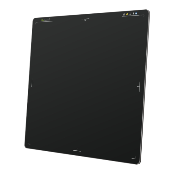
Digital Flat Panel Detector
Mars1717XF
User Manual
Before operating, please read this user manual and pay attention to all safety precautions. Please
ensure that the user manual is properly maintained so that it can be accessed at any time. Please use
correctly on the basis of full understanding of the content.
1
iRay Technology Co. Ltd.
Advertisement
Table of Contents

Subscribe to Our Youtube Channel
Related Manuals for iRay Technology Mars1717XF Series


Summary of Contents for iRay Technology Mars1717XF Series
- Page 1 Before operating, please read this user manual and pay attention to all safety precautions. Please ensure that the user manual is properly maintained so that it can be accessed at any time. Please use correctly on the basis of full understanding of the content. iRay Technology Co. Ltd.
- Page 2 Read all instructions in the user guide before operation. Pay attention to all safety precautions. Only a physician or a legally certified operator should use this product. The equipment should be maintained in a safe and operable condition by iRay Technology Co. Ltd.
- Page 3 • Information regarding specifications, components, and appearance of the product is subject to change without prior notice. Copyright iRay Technology Co. Ltd.
- Page 4 The information included is designed only for use with product. Trademarks The iRay name and iRay logo are registered trademarks of iRay Technology Co. Ltd. Symbols and Conventions The following symbols and conventions are used throughout the user guide.
- Page 5 This symbol is used to indicate the need to consult the user guide for general information. Safety Signs: please refer to the user guide for safety instructions. Safety Signs: Dangerous voltage levels. Stand-by. Handle with care. iRay Technology Co. Ltd.
- Page 6 Package symbol: keep dry. Package symbol: this symbol is used to indicate humidity range. Package symbol: keep equipment upright. Package symbol: do not roll package. Package symbol: this symbol is used to indicate stacking limit number. iRay Technology Co. Ltd.
- Page 7 To Customers Detector symbol: the device passes IPX4 test Rx Only Device is for prescription use only. iRay Technology Co. Ltd.
-
Page 8: Table Of Contents
Detector Installation 3.1.1 Attach Battery Pack ............. 28 3.1.2 Booting Up ................28 3.1.3 Adapter ................31 Operation ............................ 31 Main Operation 4.1.1 Software Mode ..............32 4.1.2 AED Mode ................34 Connection Build Panel Configuration iRay Technology Co. Ltd. - Page 9 Purpose for IT-network ............70 4.10.2 Required characteristics ............70 4.10.3 Required configuration ............70 4.10.4 Technical specifications ............70 4.10.5 Intended information flow ........... 71 4.10.6 Hazardous Situations Resulting from Failure of the IT Network iRay Technology Co. Ltd.
- Page 10 EMI Compliance Table ............77 6.3.2 EMS Compliance Table ............78 Radio Frequency Compliance Information 80 Battery Safety Standards Product Label Troubleshooting .......................... 85 Product Maintenance ........................86 Expected Service Life Regular Inspection and Maintenance 86 Repair iRay Technology Co. Ltd.
-
Page 11: Safety Information
Doing so may result in fire or electric shock. To avoid the risk of electric shock, the device must be connected to a power supply with a protective earth. Not doing so may result in fire or electric shock. iRay Technology Co. Ltd. - Page 12 Otherwise, it may result in fire or electric shock. Clean the plug of the power cord periodically by unplugging it from the AC outlet and removing dust or dirt from the plug, its periphery and the AC outlet with a dry cloth. iRay Technology Co. Ltd.
- Page 13 Doing so may result in fire or electric shock. In such situation, protect the device with a disposable cover as necessary. Turn off the power and pull out the plug to each piece of the device for safety when not used. iRay Technology Co. Ltd.
- Page 14 Be sure to securely hold the detector while using it in upright positions. Otherwise, the detector may fall over, resulting in injury to the user or patient, or may flip over, resulting in damage to the device. iRay Technology Co. Ltd.
-
Page 15: Notes For Use
Before exposure Be sure to check the device daily and confirm that it works properly. B e sure there is a battery installed in the product to avoid a sudden power off iRay Technology Co. Ltd. - Page 16 Doing so may damage the surface of the detector. It's recommended to use a waterproof non-woven cover as an isolated layer between the detector and blooding patient. iRay Technology Co. Ltd.
-
Page 17: General Description
If your configuration does not have any of these items, information about these items in the manual does not apply to your detector. 2.2 Lineup Mars □ □- □ GSI: GOS; CSI: CSI 1717: 17-inch X 17-inch Mars series iRay Technology Co. Ltd. -
Page 18: Characteristics
To acquire dark images, product shall be not influenced by imaging acquisition. To maintain data transmission, product shall be not influenced by data and signal transmission. 2.5 Product Components The product is configured with the components below Item Description iRay Technology Co. Ltd. - Page 19 General Description Mars1717XF Detector Mars1717XF GSI/CSI Medical adapter for detector and battery 24V (DC) power adapter charger 7.6V battery pack Battery pack Ethernet cable for Gigabit ethernet cable wireless router AC power cable AC cable for adapter iRay Technology Co. Ltd.
-
Page 20: Components Description
Battery charger Battery charger User Manual Paper print User Manual CD-ROM Service tool Note: The product package may be different based on requirements. 2.6 Components Description 2.6.1 Detector External Signals Input and Control Panel Control Panel iRay Technology Co. Ltd. -
Page 21: Battery Pack
Item Description DC Input Interface 24V DC input Reserved Reserved Status Indicator Detector Status indicator Reserved Reserved Link Indicator Detector Link indicator Power Indicator Detector Power indicator Power Button Power button 2.6.2 Battery Pack Item Description iRay Technology Co. Ltd. -
Page 22: Battery Charger
Show battery level after touching 2.6.3 Battery Charger Item Item Description Battery Slot 3 batteries inserted Capacity Indicator The indicator definition is as below DC Jack 24V DC input The battery charging capacity indicator definition: Indicator Lighting Status Operating Status iRay Technology Co. Ltd. -
Page 23: Product Specifications
Effective Array 2832 x 2836 (Note) Effective Area (H x V) 424.8mm x 425.4mm Greyscales 16 bit Image Transfer Wireless: IEEE802.11a/b/g/n Wireless Frequency Range 2.412~2.472GHz, 5.18~5.22GHz; 5.745~5.85GHz Data Transmission Power 13dBm (Typ.) @802.11a 16dBm (Typ.) @802.11b iRay Technology Co. Ltd. - Page 24 Note: The Mars1717XF-GSI’s active area and defect calculation area is 2832 x 2836; the TFT module size is 2848 x 2840. Please see figure below Mars1717XF GSI Active area && defect calculation area Mars1717XF GSI TFT Module size iRay Technology Co. Ltd.
- Page 25 General Description The Mars1717XF-CSI defect calculation area is 2826 x 2818, the active area is 2832 x 2836 and the TFT module size is 2848 x 2840 iRay Technology Co. Ltd.
-
Page 26: Battery
General Description 2.7.2 Battery Item Specifications Model Battery-KX Rated Capacity Min. 3500mAh, Typ.3800mAh @ Discharge 0.5C Rated Voltage 7.6V 2.7.3 Battery Charger Item Specifications Model Charger-KX iRay Technology Co. Ltd. -
Page 27: Environment
Detectors should operate at altitudes of not more than 3,000m; the requirement is only for the detector. If storing with a battery, the temperature should be in the range of -20℃~45℃ when the expected storage time is less than 3 months. For -20℃~25℃, the storage time is 12 months. iRay Technology Co. Ltd. -
Page 28: Preparation
Slide battery package into battery compartment (Make sure battery capacity overpass is 15%). Slide the battery lock lever. 3.1.2 Booting Up On the control panel, users can press the power button to turn on/off. iRay Technology Co. Ltd. - Page 29 Orange Blinking ≥7% & <15% Detector is turned on Detector is turned on Green Blinking ≥15% & <95% or detector is in sleep mode Link indicator: Link Indicator Lighting Status Description Detector is turned off iRay Technology Co. Ltd.
- Page 30 Description Blue ON Default Detector is turned off Status indicator: Status Indicator Lighting Status Description Detector is turned off Exposure prohibited Green ON Ready for exposure Orange blinking Safety Mode Orange ON Fatal Error iRay Technology Co. Ltd.
-
Page 31: Adapter
4 Operation The detector provides user SDK for integration into the DR system. Additionally, it also provides application demonstration, i.e., iDetector. 4.1 Main Operation The detector mainly acquires X-ray images. More importantly, the detector should build iRay Technology Co. Ltd. -
Page 32: Software Mode
4.1.1.2 Work flow Click “Acquire” Detector clears until warning message changes from “Exposure prohibit” to “Exposure Enable” Shoot x ray in exposure window. But the longer time user waits, the worse image would be Wait for image uploaded iRay Technology Co. Ltd. - Page 33 Note: If the wireless condition is bad, the detector cannot send even one package in 30s. It will stop trying to send image packages. Users have to retrieve images from the detector when the wireless condition is good enough. iRay Technology Co. Ltd.
-
Page 34: Aed Mode
Detector clears until warning message changes from “Exposure prohibit” to “Exposure Enable” Take X-ray in exposure window. Wait for image uploaded 4.1.2.3 Timing Setting To get a clear view of the workflow, see the diagram below for details iRay Technology Co. Ltd. - Page 35 Note: If the wireless condition is bad, the detector cannot even send one package in 30 seconds. It will stop trying to send an image package. Users have to retrieve images from the detector when the wireless is good enough. iRay Technology Co. Ltd.
-
Page 36: Connection Build
IP address is not allowed to operate when the first is connected. If there is no command transmission between the detector and the workstation (FDR SE Console or iDetector) over 5 minutes, the detector releases access authority. 4.3 Panel Configuration Choose iDetector menu-related modules iRay Technology Co. Ltd. - Page 37 Operation “Acquire” module: Choose offset mode, load gain and defect template Acquire images: “Prepacq”, “Acquire” and so on “SDK” module: IP address, MAC address and so on “Detector” module: Trigger module, wireless configuration and so on iRay Technology Co. Ltd.
-
Page 38: Pre-Offset Template Generation
On the other hand, it is also recommended to do template generation every 6 months. 4.4.1 Pre-offset Template Generation The pre-offset template is necessary for preview image. See below iRay Technology Co. Ltd. - Page 39 Operation Go to “Acquire” module, choose “HWPostOffset” Go to “Calibrate” module, click “Start Generate Templates” Click “UpdateHWPreOffset”, wait until image acquisition ends iRay Technology Co. Ltd.
-
Page 40: Gain Template Generation
Operation 4.4.2 Gain Template Generation Before gain template generation, make sure SID=1.2m; no copper is required, Go to “Acquire” module, choose “HWPostoffset” Go to “Calibrate” module, click “Start Generate Templates” iRay Technology Co. Ltd. - Page 41 Operation Click “ Create Gain” Click “Start” Set X-ray dose to meet the expected value. Click “PREP”, wait for exposure bar to count down. Before window ends, take X-ray. iRay Technology Co. Ltd.
- Page 42 Click “PREP” to start another X-ray take. Gain calibration template needs 5 X- ray images. After 5 images acquired, click “Generate”, wait until “Task succeed:FinishGenerationProcess” Note: 1. X-ray image has three states: green, yellow and red. Green means image meets requirements. iRay Technology Co. Ltd.
-
Page 43: Defect Template Generation
Red means image does not meet requirements, cannot generate template, must be taken again. 4.4.3 Defect Template Generation Before defect template generation, make sure SID=1.2m, no copper is required, Click” Create Defect” Click “Start”, Defect template needs 8 X-ray images. iRay Technology Co. Ltd. - Page 44 There will be a prompt in the box if the dosage is improper. (Note 1) Change dosage and exposure again until image is accepted. Click “Accept” if box is green, Click “PREP” to start another X-ray take. iRay Technology Co. Ltd.
-
Page 45: Local Image Check
4.5 Image Check and Upload “Local Image Check” defines the function checking image saved in the workstation (FDR SE Console or iDetector). “Panel Image Upload” defines function uploading images stored in the detector. 4.5.1 Local Image Check Choose “Local File” iRay Technology Co. Ltd. -
Page 46: Panel Image Upload
Operation Click “Local File” to open dicom, Raw and tif file Click “Open” 4.5.2 Panel Image Upload Double-check firewall is closed Panel Image is uploaded as below. iRay Technology Co. Ltd. - Page 47 Input the index number of images Click “OK” Waiting for status from "Busy" into "Ready" Check upload images Click "Stop Uploading" to stop image upload Images uploaded is stored in "work_dir \ Mars1717XF_Client \ upload \serial number" iRay Technology Co. Ltd.
-
Page 48: Defect Template Check And Modification
If the defect template has updates, the user can add and delete defect pixels or lines. 4.5.3.1 Defect Template Check Select “Local File” module Click “Local File” Choose template type “*.dft”, open it 4.5.3.2 Defect Template Modification Open defect template iRay Technology Co. Ltd. -
Page 49: Template Synchronization
The detector supports correction template storage, which means templates can be transmitted not only from the detector to the workstation(FDR SE Console or iDetector), but also from the workstation(FDR SE Console or iDetector) to the detector. iRay Technology Co. Ltd. - Page 50 Operation Make sure the firewall is turned off Choose “Calibrate”, Click “Start Generate Templates” Click “Read Status” besides “Subset settings” iRay Technology Co. Ltd.
- Page 51 Operation Click the template to be downloaded Click “Download to FPD” Check whether information is right. Change Index in FPD if necessary. Click “Download”. Wait until “Task succeed: Download CaliFile” iRay Technology Co. Ltd.
- Page 52 Operation Click “Read Status” to read template Choose template number according to requirements Click “Active” to activate template Upload templates Make sure firewall is turned off iRay Technology Co. Ltd.
- Page 53 Click “Start Generate template” Click “Read status” besides FPD template file. Click template which needs to be uploaded. Click subset settings Click “upload to Workdir”. If information listed is right, click “OK”. Wait until “Upload FPD file succeed!” iRay Technology Co. Ltd.
-
Page 54: Correction Activation
The detector supports two ways to do corrections. Software correction defines a scenario in which the workstation(FDR SE Console or iDetector) finishes a correction. If the detector does itself, that is hardware correction and calibration. 4.6.2.1 Software Correction Make sure templates are saved in “work_dir\Mars1717XF_192.168.100.8\ Correct\Default” Choose “Acquire” iRay Technology Co. Ltd. - Page 55 Operation Offset mode “SWPostOffset”, Gain mode “SWGain”, Defect mode “SWDefect” 4.6.2.2 Hardware Correction Click “Read Status” to read template iRay Technology Co. Ltd.
- Page 56 Gain mode “HWGain” Defect mode “HWDefect” 4.7 Firmware Update The detector supports firmware updating with the website; if the user needs to update firmware, please follow the steps below Preparation before updating Go to page “Detector” iRay Technology Co. Ltd.
- Page 57 Operation Change Trigger mode to “TriggerMode_Prep” Change Prep Capmode to “PrepCapMode_Acq2” Click “Write” Firmware updating Open IE browser. Input 192.168.100.8 User name: admin Password: iray Click button in red box Choose “upgrade” iRay Technology Co. Ltd.
- Page 58 Double-click left mouse: image displayed in center with maximum size. Press and drag left mouse: drag image displayed. “F3”: Quickly adjust the image window width and window level. iRay Technology Co. Ltd.
-
Page 59: Main Gui
Detector configuration, synchronization methods, etc. Calibrate Correction template generation and management Local File Local image check and image processing 4.9.2 Home Page Item and button description are shown as follows. Item Function description Name Detector name Detector SN number iRay Technology Co. Ltd. -
Page 60: Acquire Page
The user can rotate images and do other image processing with “ROI”. Figure 4.13.2 The state of the detector, SN and Message is on the bottom of the page. Item Function description Connected detector SN number iRay Technology Co. Ltd. - Page 61 Save image frames in continuous image acquisition mode (document type and path can be set) Image Properties/ Functional description Image Process Window width Window level PosX Cursor X coordination PosY Cursor Y coordination Value Value of cursor Width Image width iRay Technology Co. Ltd.
- Page 62 Drag left mouse: drag image displayed. • Lateral drag right mouse: adjust window width • Vertical drag right mouse: adjust window level • F3: Quickly adjust window width and level. Note: correlation between image acquired and physical panel direction Image Panel iRay Technology Co. Ltd.
-
Page 63: Sdk Page
Operation 4.9.4 SDK Page The page is used to configure config.ini and set log level in real time, as shown below iRay Technology Co. Ltd. -
Page 64: Detector Page
Parameter tab is activated in default. Five boxes on the page are defined as follows: Zone 1: parameters Zone 2: parameters reading from detector Zone 3: parameters written into detector Zone 4: function button Zone 5: simple message from detector and state iRay Technology Co. Ltd. - Page 65 Static X-ray synchronization mode Fluro Sync Dynamic X-ray synchronization mode Set Delay Time Delay time for “prepacq” Acquire Delay Reserved Integrate Time Reserved Tube Ready Reserved Function button description Function Button Description Reset Detector Reboot detector iRay Technology Co. Ltd.
- Page 66 Write configuration Upgrade Firmware Reserved 4.9.5.2 Sensor This page includes temperature and humidity information. Sensor Description Modifiable Temperature Read temperature in detector Humidity Read humidity in detector 4.9.5.3 Wireless configuration Mode should be checked with client. iRay Technology Co. Ltd.
- Page 67 Check wireless link status in detector Read WiFi Status Scan SSID in air with FPD wifi module Scan from FPD Wireless link status is shown in this area Wifi Status Info Available wireless networks are shown in this area Wireless Network iRay Technology Co. Ltd.
- Page 68 Acquisition delay time Delay time Image type Image attr Note: 1. If “HWPostoffset” is chosen, the image saved in the detector will be the corrected one. If not or “SWPostoffset” is chosen, it will be the incorrect one. iRay Technology Co. Ltd.
-
Page 69: Calibrate Page
Operation 4.9.6 Calibrate Page This page works for template management and generation. Function Button Description Start to Generate Templates Start template generation and template management 4.9.7 Local File Page This page works for local image check. iRay Technology Co. Ltd. -
Page 70: Purpose For It-Network
They must support IEEE 802.11.a/b/g/n. 4.10.4 Technical specifications(Only for CE) Image Transfer Wireless: IEEE802.11a/b/g/n Wireless frequency range 2.412~2.472GHz, 5.18~5.22GHz;5.745~5.85GHz Data Transmission Power 13dBm (Typ.) @802.11a 16dBm (Typ.) @802.11b 14dBm (Typ.) @802.11g 13dBm (Typ.) @802.11n HT20 11dBm (Typ.) @802.11n HT40 iRay Technology Co. Ltd. -
Page 71: Intended Information Flow
Connection of the main unit to an IT-network that includes other equipment can result in previously unidentified risks. The manufacturer of the X-ray machine should identify, analyze, evaluate and control these risks. Subsequent changes to the IT-network can introduce new risks and require additional analysis. iRay Technology Co. Ltd. -
Page 72: Changes To It Network Include
Operation 4.10.8 Changes to IT Network Include: changes in IT network configuration; connection of additional items to IT network; disconnecting items from IT network; update of equipment connected to IT network. iRay Technology Co. Ltd. -
Page 73: Charger Installation
Charger Installation 5 Charger Installation Insert battery into battery charger Note: Insert direction as in figure Make sure the battery is inserted to the bottom of the opening Unload battery from charger after charging completes. iRay Technology Co. Ltd. -
Page 74: Regulatory Information
6 Regulatory Information Product safety regulatory information includes safety of the detector, charger and other accessories. 6.1 Manufacturer’s Information COMPANY: iRay Technology Co., Ltd ADDRESS: Rm. 202, Building 7, No. 590, Ruiqing Rd., Zhangjiang East, Pudong, Shanghai, China ZIP CODE: 201201... - Page 75 Medical electrical equipment – Part 1: General ANSI/AAMI ES60601- requirements for basic safety and essential 1:2005/(R)2012+A1:2012+C1:2009/(R)2012+A2:2010/(R)2012 performance Medical electrical equipment –Part 1: General CAN/CSA-C22.2 No.60601-1:14 requirements for basic safety and essential performance iRay Technology Co. Ltd.
- Page 76 — Collateral standard: Usability Medical electrical equipment Part 1-6: General KS C IEC 60601-1-6:2011 requirements for basic safety and essential performance — Collateral standard: Usability Medical electrical equipment Part 1-6: General EN 60601-1-6:2010+A1:2015 requirements for basic safety and essential iRay Technology Co. Ltd.
-
Page 77: Guidance And Manufacture's Declaration For Emc
6.3 Guidance and manufacture’s declaration for EMC 6.3.1 EMI Compliance Table Emissions Phenomenon Compliance Electromagnetic environment RF emissions CISPR 11 Professional healthcare facility environment Group 1, Class B Harmonic distortion IEC 61000-3-2 Professional healthcare facility environment iRay Technology Co. Ltd. -
Page 78: Ems Compliance Table
Near fields from RF wireless communications equipment Test frequency Band Immunity test levels (MHz) (MHz) Professional healthcare facility environment 380-390 Pulse modulation 18Hz, 27V/m 430-470 FM, ±5kHz deviation, 1kHz sine, 28V/m 704-787 Pulse modulation 217Hz, 9V/m 800-960 Pulse modulation 18Hz, 28V/m iRay Technology Co. Ltd. - Page 79 Portable RF communications equipment, including antennas, can effect medical electrical equipment. The warning should include a use distance such as “be used no closer than 30 cm (12 inches) to any part of the [ME EQUIPMENT or ME SYSTEM], including cables specified by the manufacturer”. iRay Technology Co. Ltd.
-
Page 80: Radio Frequency Compliance Information
(cellular) telephones. Electromagnetic interference may result in incorrect operation of the system and a potentially dangerous situation. The Mars1717XF series wireless flat panel detector should not be stacked with or adjacent to other devices. If inevitable, verify the detector. -
Page 81: Battery Safety Standards
Household and commercial batteries IEC 62133:2012 Secondary cells and batteries containing alkaline or other non- acid electrolytes UN38.3 United Nations Recommendations on the Transport of dangerous goods Manual of tests and Criteria ST/SG/AC.10/11/Rev.5/Amend.1&Amend.2 6.6 Product Label Mars1717XF-GSI Detector Label iRay Technology Co. Ltd. - Page 82 Regulatory Information Mars1717XF CSI Detector Label Battery Charger Label iRay Technology Co. Ltd.
- Page 83 Regulatory Information Battery Label iRay Technology Co. Ltd.
- Page 84 Regulatory Information iRay Technology Co. Ltd.
-
Page 85: Troubleshooting
Trouble shooting 7 Troubleshooting Please refer to the service manual. If the problem remains unsolved, turn off the detector and contact the Fujifilm service department. We will provide the best service possible. iRay Technology Co. Ltd. -
Page 86: Product Maintenance
Contact Fujifilm after-sales service departments or authorized product distributors. 8.3 Repair If a problem cannot be solved, contact your sales representative or local dealer. Please provide the following information: Product Name: Series Number: Description of Problem: as clearly as possible. iRay Technology Co. Ltd. - Page 87 Appendix iRay Technology Co. Ltd.
Need help?
Do you have a question about the Mars1717XF Series and is the answer not in the manual?
Questions and answers