Table of Contents
Advertisement
420-0040UK
1
PRINTING
ST
SEGA AMUSEMENTS INTERNATIONAL LTD.
42 Barwell Business Park, Leatherhead Road
Chessington, Surrey
KT9 2NY
United Kingdom
Telephone: +44 (0) 208 391 8090
Facsimile: +44 (0) 208 391 8099
Email: sales@segaarcade.com
Web: http://www.segaarcade.com
© Kaizen Entertainment
Errors & Omissions Excepted (E&OE)
SERVICE MANUAL
IMPORTANT
• Before using this product, read this Manual carefully to understand
the contents herein stated
• After reading this Manual, be sure to keep it near the product or in
a convenient place for easy reference when necessary
Advertisement
Table of Contents

Related Manuals for Sega bop it ARCADE


Summary of Contents for Sega bop it ARCADE
- Page 1 420-0040UK PRINTING SERVICE MANUAL SEGA AMUSEMENTS INTERNATIONAL LTD. 42 Barwell Business Park, Leatherhead Road Chessington, Surrey KT9 2NY United Kingdom Telephone: +44 (0) 208 391 8090 Facsimile: +44 (0) 208 391 8099 Email: sales@segaarcade.com Web: http://www.segaarcade.com IMPORTANT • Before using this product, read this Manual carefully to understand the contents herein stated ©...
- Page 2 BEFORE USING THE PRODUCT, BE SURE TO READ THE FOLLOWING: TO MAINTAIN SAFETY: To e n s u r e t h e s a f e o p e r a t i o n o f t h i s p r o d u c t , b e s u r e t o r e a d t h e f o l l o w i n g b e f o r e u s a g e : The following instructions are intended for the users, operators and the personnel in charge of the operation of the product.
- Page 3 SEGA shall not be held responsible for any accidents or compensation for damage to a third party resulting from the specifications not designated by SEGA • Ensure that the product meets the requirements of appropriate electrical specifications:...
- Page 4 "BOP IT ARCADE" This Manual is intended for the owners and personnel managers in charge of operation of this product. Operate the product after carefully reading and sufficiently understanding the instructions.
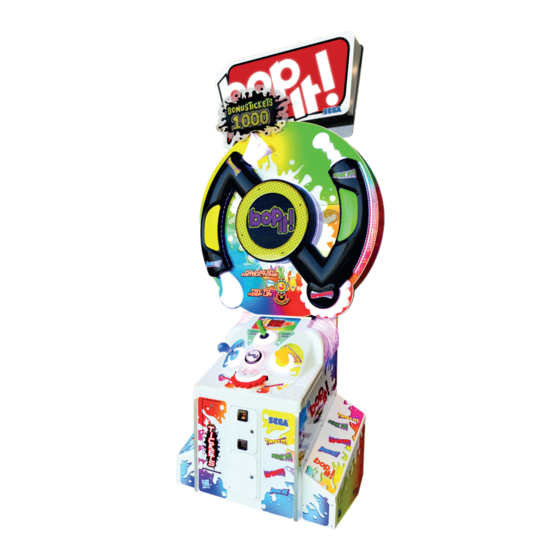
- Page 5 SPECIFICATIONS Standard Cabinet Machine Dimensions: 1.2m (47.2in) [Width] x 0.7m (27.5in) [Depth] Machine Height: 2.68m (105.5in) (Installed) Machine Weight: 166kg Approx (Installed) (366lbs) Power, maximum current: -220w- Rating: 115-230VAC @ 50/60Hz Fuse Rating: 3.15A INDIVIDUAL SPECIFICATIONS Main Cabinet Main Display H = 1.61m H = 1.35M W = 1.2M W = 1.02m D = 0.7m D = 0.35M...
- Page 6 Definition of 'Site Maintenence Personnel’ or Other Qualified Individuals Definition of 'Site Maintenence Personnel’ or Other Qualified Individuals Procedures not described in this Manual or marked as ‘to be carried out by Site Maintenance Personnel or other qualified professionals’ should not be carried out by personnel without the necessary skill or technological experience. Work carried out by unqualified persons may cause serious accidents, including electrocution Parts replacement, maintenance inspections, and troubleshooting should be carried out by site maintenance personnel or other qualified professionals.
- Page 7 The symbol shown below will be placed on all products manufactured from 13th August 2005, which indicates this product must NOT be disposed of with other normal waste. Upon purchasing any EEE from SEGA Amusements International Ltd., the user accepts responsibility to dispose of their waste equipment by arranging to return it to a designated UK collection point (AATF) or an Approved Exporter (AE) for the correct recycling of waste electrical and electronic equipment.
-
Page 8: Table Of Contents
TABLE OF CONTENTS INTRODUCTION HANDLING PRECAUTIONS PRECAUTIONS REGARDING INSTALLATION PRECAUTIONS REGARDING OPERATION 3-1 Before Operation 3-2 Paying Attention to Customers PARTS DESCRIPTION ACCESSORIES ASSEMBLY AND INSTALLATION 6-1 Unpacking the Cabinet 6-2 Installing the Main Display 6-3 Installing the Billboard 6-4 Fixation to Site 6-5 Confirmation of Installation 6-6 Components that Change State 6-7 Replacing Tickets... - Page 9 COIN HANDLING 11-1 Cleaning the Coin Selector 11-2 Fault Finding 11-3 Adjusting the Price of Play (Excel) 11-4 Coin Region & Price of Play Settings 11-5 Price of Play Quick Start (USA) 12 12 LAMPS AND LIGHTING 12-1 Coin Door Lamp 12-2 Cabinet LED List 12-3 LED Diagrams 13 13...
-
Page 10: Handling Precautions
Noncompliance with this instruction can have a bad influence upon the physical conditions of players or onlookers, or result in injury during play • SEGA shall not be held responsible for damage or compensation for damage to a third party caused by specification changes not designated by SEGA •... - Page 11 • Some parts are not designed or manufactured specifically for this game machine. The manufacturers may discontinue or change the specifications of such general-purpose parts. If this is the case, SEGA cannot repair or replace a failed game machine whether or not a warranty period has...
- Page 12 CONCERNING THE STICKER DISPLAY This SEGA product has stickers attached describing the product manufacture No. (Serial No.) and Electrical Specifications. It also has a Sticker describing where to contact for repair and for purchasing parts. When inquiring about or asking for repairs, mention the Serial No. and Name of Machine indicated on the Sticker.
- Page 13 CAUTION PINCH POINT CAUTION 440-CS0371UK 440-CS0371UK QUALIFIED PERSONNEL ONLY Take care when servicing within these areas 440-CS0010UK 440-CS0010UK CAUTION QUALIFIED PERSONNEL ONLY Take care when servicing within these areas LB1131 440-CS0010UK 440-CS0010UK LB1131 PORTABLE APPLIANCE TEST RECORD 3.15A DATE ENGINEER VISUAL PASS EARTH BOND INSULATION...
-
Page 14: Precautions Regarding Installation
PRECAUTIONS REGARDING INSTALLATION PRECAUTIONS REGARDING INSTALLATION • This product is an indoor game machine. Do not install it outside. Even indoors, avoid installing in places mentioned below so as not to cause fire, electric shock, injury and/or malfunction: • Places subject to rain/water leakage or places subject to high humidity, in the proximity of an indoor swimming pool and/or shower, etc •... - Page 15 • For safe operation, use and operate this product in an area measuring at least 1.84m (72.4in) in width and 1.28m (50.3in) in depth when the Cabinet is installed. SEGA shall not be held responsible for damage or compensation for damage to a third party, resulting from the failure to observe this instruction •...
- Page 16 • To install this product, the entrance must be at least 0.7m (27.5in) in width and 2.44m (96.1in) in height without Assy Billboard and 2.68m (105.5in) with Assy Billboard • If the entrance is too narrow, do not tilt the product carelessly. If all the product weight is put on the castors at one side only, there could be damage or deformation, causing serious accidents such as workers getting caught underneath...
-
Page 17: Precautions Regarding Operation
PRECAUTIONS REGARDING OPERATION To avoid injury and trouble, be sure to pay attention to the behaviour of visitors and players. 3-1 BEFORE OPERATION • In order to avoid accidents, check the following before starting the operation: • To ensure maximum safety for the players and the customers, ensure that where the product is operated has sufficient lighting to allow any warnings to be read. - Page 18 • To avoid injury, be sure to provide sufficient space by considering the potentially crowded situation at the installation location. Insufficient installation space can cause contact, collisions, and/or trouble between customers • During daily cleaning, be sure to check the surface of the Control Unit and other parts that the player touches with his/her hands for damage, cracks, or loose screws.
-
Page 19: Paying Attention To Customers
3-2 PAYING ATTENTION TO CUSTOMERS To avoid injury and trouble, be sure to constantly give careful attention to the behaviour and manner of the visitors and players. DURING OPERATION (PAYING ATTENTION TO CUSTOMERS) • For safety reasons, do not allow any of the following people to play the game: Those who have high blood pressure or a heart problem Those who have experienced muscle convulsion or loss of consciousness when playing video games, etc... - Page 20 • Diligently clean the parts that players touch directly to ensure a pleasant game playing experience • Inspect the coin insertion slots to make sure no foreign objects have been inserted and that they have not otherwise been tampered with as this will prevent play •...
-
Page 21: Parts Description
PART DESCRIPTIONS Ticket Door Coin Door Control Panel + Control Units LED Game Display LED Billboard Display Billboard Score Count... -
Page 22: Accessories
ACCESSORIES Confirm that the accessories listed in the table below are present when setting up the product. Accessories marked “Spare” are consumable items but included as spares. Part Name / Number Diagram Quantity Owner’s Manual (Part #: 420-0040UK) Master Key (J9117) Security Key (A444) Power Lead UK (Pt No LM1227) EU (Pt No LM1246) -
Page 23: Assembly And Installation
ASSEMBLY AND INSTALLATION ● Perform assembly work by following the procedure herein stated. Failure to comply with the instructions can cause electric shock ● Perform assembling as per this Manual. Since this is a complex machine, incorrect assembling can cause an electric shock, machine damage and/or improper functioning as per specified performance ●... - Page 24 ● Handle molded parts with care. Excessive weight or pressure may cause them to break and the broken pieces may cause injury ● To perform the operation safely and accurately you must use a safe, steady footstool or stepladder. Working without this may lead to a fall and possible injury ●...
-
Page 25: Unpacking The Cabinet
6-1 UNPACKING THE CABINET Remove top packaging cover and pallet sleeve Remove securing strap and bar strap board... -
Page 26: Installing The Main Display
6-2 INSTALLING MAIN DISPLAY Remove the Billboard from the Main Cabinet by removing the (4) securing fixings and set the Billboard to one side Remove the top packaging from the Display Cab sleeve (IMPORTANT - DO NOT attempt to move the Display Cabinet in or from the outer box before properly removing all packaging as this could irreperably damage the Display Cabinet) Main Cab... - Page 27 Remove the (3) transit fixings of the Display Cabinet that secure the Transit Board to the pallet Transit Fixings Transit Board Remove the Door Box Display Back by removing the (2) fixings and unlocking with the supplied key Fixings Lock Remove the Display Cabinet from the pallet. Remove the Main Cabinet from the pallet and place into position behind the Display Cabinet with the front of the Cabinet facing towards the Display Cabinet Main Cab Display Cab...
- Page 28 Apply the (2) Stabilizer Backs into position at the Rear Base of the Main Cabinet (note: adjust Stabilizer Feet to be in contact with the floor) Stabilizer Backs Remove the (2) Bolts securing the Display Cabinet to the Transit Board. Remove the bolt from each of the transit brackets securing the Display Cab (IMPORTANT - take care when removing the bolts as the Display Cabinet can potentially move freely due to its shape).
- Page 29 Using at least 2 people, raise and place the Display Cab into position over the Strut Display Support Brackets (raise Display Cab using grab points to lift). Secure the (3) fixings on each bracket to secure the Display Cab into position Fixings Grab Points Strut Display...
-
Page 30: Installing The Billboard
6-3 INSTALLING THE BILLBOARD From the rear of the Cabinet, raise the Billboard into position and insert as shown Billboard Here Secure using the (6) highlighted fixings Fixings Fixings Feed the harnessing of the Billboard through the hole in the Bonus Box Bracket and connect to the location shown Feed Harness here... - Page 31 Apply and secure Cover Back Box using the (2) fixings (one fixing on the top, one fixing on the bottom) Fixings Apply the Plate Bonus Box artwork into the position shown using the (2) M6 fixings and self-clinch nuts on each side SC Nut Fixings...
-
Page 32: Fixation To Site
6-4 FIXATION TO INSTALLATION SITE Make sure that all the adjusters contact the floor. Otherwise the Cabinet could move, causing an accident The product comes with castors attached at 2 locations and adjusters at 2 locations. When the installation site has been determined, have the adjusters come in direct contact with the floor. Establish a gap of about 5 mm between the floor and the castors and adjust the unit so that it will remain level. - Page 33 ADJUSTER CASTOR Approx. 5 mm ADJUSTER CONNECTION OF POWER AND GROUND CABLES (Only applies where an integral earth is not present in the mains/power lead.) ● Use the power supply equipped with an earth leakage breaker. Use of power supply without such a breaker could result in fire if there is a current leakage ●...
- Page 34 If grounding has been established with the ground wire inside the power cord, do not perform grounding with the AC unit ground terminal. Conversely, if the AC unit ground terminal has been used for grounding, do not establish ground with the ground wire in the power cord.
-
Page 35: Confirmation Of Installation
6-5 CONFIRMATION OF INSTALLATION Use Test Mode to confirm that assembly is proper, connecting boards, and input/output devices are normal. See Section 9 “Test and Service Data” for more information on each individual test. Perform the following tests in Test Mode: Unlock and open the Coin Door to access the SW Unit. -
Page 36: Components That Change State
6-6 COMPONENTS THAT CHANGE STATE UPON POWERING UP Billboard illuminates Bonus Box Screen powers on Bop It Model illuminates Score Screen powers on Main Display illuminates LED Clusters illuminate Control Panel illuminates Downlight illuminates... -
Page 37: Replacing Tickets
6-7 REPLACING TICKETS Unlock and open the Ticket Mech Door that needs loading or replacing Unlock Ticket Door here Load tickets into the Ticket Mech as shown below and feed into the dispensing track Ensure tickets are vended correclty by pressing the Test Button on the Ticket Mech (tear off and remove excess tickets that are vended after testing) Close Ticket Mech Door and ensure lock is secure... -
Page 38: Precautions When Moving
PRECAUTIONS WHEN MOVING 7-1 MOVING THE MACHINE ● Always disconnect the power cable before moving the product. If it is moved with the power cable connected, the cable could be damaged, causing fire or electric shock ● To move the unit over the floor, pull in the adjustors and have the castors contact the floor. - Page 39 ● When moving the Cabinet, do not hold, push, or pull the Control Units. This may disfigure or damage them ● If you need to move components through a narrow or low door and the only way to get the separated components through is to turn them on their side, or if a separation method other than those described in this Manual is required, either make a request to the office listed in this document or the place of purchase to perform the operation or contact them regarding how to perform...
-
Page 40: Game Description
GAME DESCRIPTION 8-1 GAME OUTLINE Coin system can accumulate up to 24 Credits. Credits beyond 24 will not be counted and returned to Player. When the 24 Credit limit is reached, it will be recorded in the Test Menu under Coin Settings > Coin Count. - Page 41 Standard Game Settings Overview This page contains parameter adjustment functions for Game Modes. For more detail on Game Settings see TEST MODE – GAME SETTINGS. • Pressing the TEST button will activate the selected Game Setting Function • Pressing the SERVICE button will move to the next available test function. The following settings are set as default at manufacturing.
-
Page 42: Test And Service Data
EXPLANATION OF TEST AND DATA DISPLAY Do not touch any parts that are not specified in these directions. Touching unspecified locations may lead to electric shock or cause short circuits ● Be careful that your finger or hand does not get caught when opening/closing the coin chute door Credit Board Located Here... -
Page 43: Switch And Coin Meter
9-1 SWITCH UNIT AND COIN METER The Swith Unit and Counters are housed within the Coin Tower. To access these controls you will need to open the Coin Door. The switches and counters can be found directly on the rear face of the Tower. Coin Counter Ticket Counter Vol + Button... -
Page 44: Game Test Mode
9-2 GAME TEST MODE TEST MODE Test Mode is entered by pressing the TEST button. The cabinet LED Matrix will display the word “test “ TEST FUNCTIONS NOTE: The term ‘CALL’ and ‘CALL OUT’ used within these instructions refer to the vocal instructions to action the BOP IT - TWIST IT - FLICK IT - PULL IT - SPIN IT controllers. - Page 45 SET TICKET VALUE VALUE: 0.01 This function sets Ticket Value. Pressing the TEST button will cycle through the following values: • 0.001, 0.002, 0.005, 0.01, 0.02, 0.03, 0.04, 0.05, 0.06, 0.07, 0.08, 0.09, 0.10 Set Ticket Mode SET TICKET MODE SETTING: FULL This function sets Ticket Value with respect to FULL value or HALF value.
- Page 46 This sets the amount the BONUS TARGET value is increased by after a Bonus Ticket win. Pressing the TEST button will set the BT incremental step by the following values: • 1 – 10 in increments of 1. In this example once the player has reached 55 call outs, they are awarded the bonus tickets and the Bonus Score increases by 5 to 60.
- Page 47 SET CALL TKT GAME 1-10: 1 This sets the ticket value for games 1 – 10 ( Zone 1 ) Ticket range 0 - 2 Pressing the TEST button will cycle through increments of 1. Set Call Out Ticket Values SET CALL TKT Default Setting GAME 11-20: 1...
- Page 48 SET CALL TKT GAME 51-60: 1 This sets the ticket value for games 51 - 60. ( Zone 6 ) Ticket range 1 - 12 Pressing the TEST button will cycle through increments of 1. Set Call Out Ticket Values SET CALL TKT Default Setting GAME 61-70: 1...
- Page 49 SET ACTIVE TIME1 SETTING: 2.00s This sets the period each controller is active for during games 1 - 10. Range 3.00s, 2.50s, 2.00s, 1.75s, 1.50s. 1.25s, 1.00s, 0.75s, 0.50s Pressing the TEST button will cycle through setting options. ...
-
Page 50: Bookkeeping
SET ACTIVE TIME9 SETTING: 0.50s Set Call Out frequency intervals. SET ACTIVE TIME10 Default Setting SETTING: 0.50s FREE GAME MODE – (PLAY FOR FUN ONLY) Exiting Game Settings After making Game Setting changes you will be prompted to confirm your decision. ... - Page 51 AV TCEKT = 000030 AV SCORE = AV TCKET – The average amount of tickets paid out per game. AV SCORE – The average score value. Bookkeeping Screen 4 BNS 1 IN = BNS WIN BNS 1 IN –...
- Page 52 ZONE 9 = ZONE 10 = ZONE 9 - The number of C/Outs won in Zone 9. ZONE 10 - The number of C/Outs won in Zone 10. Bookkeeping Screen 10 MERCY CONTINUE MERCY - The number of Mercy games played. ...
-
Page 53: System Info
System Info contains general information and version numbers for system hardware and software Pressing the SERVICE button will cycle through the available test functions. Pressing the TEST button will activate the selected Test Function • Operation Game Name and Version Info BOP IT ARCADE Version 1.00S Hardware and Serial Number Info... -
Page 54: Lighting Test
BOOTLOADER: v1.0 Serial: 0123ABCD 4. LIGHTING TEST • General Lamp Test contains test functions for the lighting elements of the Cabinet Pressing the TEST button will activate the selected Test Function • Operation All Lamps Test All Lamps • When OFF is displayed, all lamps in the cabinet will be OFF •... - Page 55 Display Test ALL SEGMENTS SEGMENTS OFF Pressing TEST will cycle through the 7-SEG LED test modes: • ALL OFF – All 7 Segment Display elements are OFF ALL ON – All 7 Segment Display elements are ON Identify IDENTIFY CALOUT = 43 Pressing TEST will display 431 on the TICKETS 7 SEG LED display...
-
Page 56: Input Test
MATRIX SHOW IMP = 01 • Pressing TEST will cycle through the LED Matrix animations & messages. 6. INPUT TEST Switch Inputs DIL SW1-6 000000 TST–OFF SRV-OFF • The current status of all on-board DIL inputs is shown on the display. “0”... -
Page 57: Audio Settings
Ticket Output TICKET OUTPUTS TICKET VEND • If TEST is pressed, the Selected Ticket Vend will dispense until the opto signal is received. TICKET OUTPUTS VEND OK Meter Test METER OUTPUTS TEST GAME METER • If TEST is pressed, the Selected Meter Output will be pulsed one (1) unit to validate the Meter Output driver. -
Page 58: Date/Time
Volume is controlled by Up / Dn pushbuttons located next to the TEST & SERVICE buttons. A minimum volume setting is enabled to ensure the game instructions can be heard irrelevant of the volume control position. Pressing the TEST button will activate the selected Audio Function Pressing the SERVICE button will move to the next available test function. - Page 59 Set Date SET DATE/TIME 20/07/22 13:30 Pressing TEST once will activate the Date/Time setting and place a flashing cursor underneath the first field (DATE) Pressing the SERVICE button will move the cursor along the fields in the following sequence: DATE ...
-
Page 60: Controller Unit
CONTROLLER UNIT • When working with the product, be sure to turn the power off. Working with the power on may cause an electric shock or short circuit • Be careful not to damage the wires. Damaged wires may cause an electric shock, short circuit or present a risk of fire •... -
Page 61: Replacing The Control Units
10-1 REMOVING THE CONTROL UNITS 10-1-1 - Removing the "Flick-It" Control Unit With the power OFF. Unlock and remove the Door Back Lower Disconnect the related harnessing Remove the (4) flange nuts on the fixings highlighted and remove the assembly... - Page 62 10-1-2 - Removing the "Pull-It" Control Unit With the power OFF. Unlock and remove the Door Back Lower Disconnect the related harnessing Remove the (4) flange nuts on the fixings highlighted and remove the assembly...
- Page 63 10-1-3 - Removing the "Twist-It" Control Unit With the power OFF. Unlock and remove the Door Back Lower Disconnect the related harnessing Remove the (4) flange nuts on the fixings highlighted and remove the assembly...
- Page 64 10-1-4 - Removing the "Spin-It" Control Unit With the power OFF. Unlock and remove the Door Back Lower Disconnect the related harnessing. Remove the (1) fixing from the Cabinet front Remove the (4) M6 fixings highlighted and remove the assembly (be sure to support the controller from underneath when removing these fixings)
- Page 65 10-1-5 - Removing the "Bop-It" Control Unit In order to remove the "Bop-It" Controller, the Spin It controller must first be removed. Consult Section 10-1-4 in order to see how the Spin It Controller is removed. With the power OFF. Unlock and remove the Door Back Lower Disconnect the related harnessing Remove the (4) flange nuts on the fixings highlighted and remove the assembly...
-
Page 66: Coin Handling
COIN HANDLING Handling the Coin Jam If the coin is not rejected when the REJECT button is pressed, open the coin chute door and open the selector gate. After removing the jammed coin, put a normal coin in and check to see that the selector correctly functions. 11-1 CLEANING THE COIN SELECTOR ●... - Page 67 CLEANING THE COIN SELECTOR (MECHANICAL) Remove and clean smears by using a soft cloth dipped in water or diluted chemical detergent and then squeezed dry. Remove the CRADLE. When removing the retaining ring (E ring) be very careful so as not to bend the rotary shaft. Remove stain from the rotary shaft and shaft CRADLE receiving portions by wiping off with a soft cloth.
- Page 68 CLEANING THE COIN SELECTOR (SR3 / NRI) Remove and clean smears by using a damp soft cloth dipped in water. DO NOT use any diluted chemical detergent or cleansing agent as this will impair the workings of the component. GATE Open the reject gate to gain access to the rundown path.
-
Page 69: Fault Finding
11-2 FAULT FINDING Fault Finding The following information is presented for customers’ guidance in rectifying a fault but does not cover all possible causes. All acceptors with electronic faults should be returned to an approved service centre for repair. SYMPTOM INVESTIGATE POSSIBLE CAUSE Poor Contact... -
Page 70: Adjusting The Price Of Play (Excel)
11-3 ADJUSTING THE PRICE OF PLAY (EXCEL) ● The price of play is determined by the configuration of switches located on either the EXCEL or VTS board. The type of board used is determined by product location. Switch settings for both types of board remain the same This product comes equipped with a Crane NRI Coin Acceptor. -
Page 71: Coin Region & Price Of Play Settings
11-4 COIN REGION & PRICE OF PLAY SETTINGS... - Page 72 PRICE OF PLAY BONUS DIL SWITCH 1 0.10 0.10 0.50 = 6 credits 0.20 0.20 0.50 = 3 credits 0.30 0.30 1.00 = 4 credits 0.30 0.50 = 2 credits 0.30 1.00 = 3 credits 0.40 0.40 1.00 = 3 credits 0.50 0.50 1.00 = 3 credits...
-
Page 73: Price Of Play Quick Start (Usa)
11-5 PRICE OF PLAY QUICK START - USA DIL SWITCH BANK ONE (5 way SW1) Item Price 25cent 50cent 75cent $1.00 $2.00 DIL SWITCH BANK TWO (6 way SW3) Type... -
Page 74: Lamps And Lighting
LAMPS AND LIGHTING • When working with the product, be sure to turn the power off. Working with the power on may cause an electric shock or short circuit • You may get burned by a hot fluorescent lamp or other lamps. Pay full attention to the lamps when performing the work •... -
Page 75: Cabinet Led List
12-2 CABINET LED LIST Related Assembly Lighting Part # + Description BI-6001UK ASSY BB TOP BI-0500UK BI-6002UK ASSY BILLBOARD ASSY BB SHORT BI-6003UK ASSY BB MID EP1421 LED 12V RED RS 541-40722 BI-1000UK ASSY MAIN CABINET BI-6004UK ASSY LED FLOOR BI-1550/1550UK SAI-6201-0200UK ASSY LED CLUSTER L/R ASSY RGB LED SH BI-2100UK 838-0039UK... -
Page 76: Led Diagrams
12-3 CABINET LED LOCATIONS BI-2200UK - ASSY PULL IT 390-2512-106RGB BI-2300UK - ASSY FLICK IT 390-2512-106RGB... - Page 77 BI-2400UK - ASSY TWIST IT 390-2512-106RGB BI-2600UK - ASSY CTRL PUSH IT 390-2512-106RGB/509-6003-C-RGB...
- Page 78 BI-1000UK + 2100UK - ASSY MAIN CAB + CONTROL PANEL BI-6006UK SAI-6201-0200UK SAI-6201-0200UK SAI-6101-0220UK EP1421 BI-6004UK BI-3000UK - ASSY MAIN DISPLAY 838-0052UK 838-0052UK 838-0052UK 838-0052UK...
- Page 79 BI-3000UK - ASSY MAIN DISPLAY 390-2805-3232P5 BI-3100UK - ASSY BONUS BOX 390-2805-3232P5...
- Page 80 BI-0500UK - ASSY BILLBOARD BI-6001UK BI-6002UK BI-6003UK...
-
Page 81: Periodic Inspection
PERIODIC INSPECTION The items listed below require periodic check and maintenance to retain the performance of this machine and to ensure safe business operation. When handling the controller, the player will be in direct contact with it. In order to always allow the player to enjoy the game, be sure to clean it regularly. - Page 82 Cleaning the Cabinet Surfaces When the Cabinet surfaces are badly soiled, remove stains with a soft cloth dipped in water or diluted (with water) chemical detergent and squeezed dry. To avoid damaging surface finish, do not use solvents such as thinner, benzine, etc. other than ethyl alcohol, or abrasives, bleaching agent and chemical dustcloth. Some general-purpose household, kitchen and furniture cleaning products may contain strong solvents that degrade plastic components, coatings, and print.
-
Page 83: Troubleshooting
TROUBLESHOOTING 14-1 TROUBLESHOOTING (WHEN NO ERROR MESSAGE IS SHOWN) • This work should be performed by site maintenance personnel or other skilled professionals. Work performed by non-technical personnel can cause a severe accident such as an electric shock. If there are no site maintenance personnel or other skilled professionals available, turn off the power immediately and contact the office given in this Manual or from point of purchase •... - Page 84 The table above shows a list of possible failures and a brief solutions. If problems persist further or there are aditional issues which may not be listed here. Please contact you point of sale or the SEGA Service Department on...
-
Page 85: Game Board
GAME BOARD • When working with the product, be sure to turn the power off. Working with the power on may cause an electric shock or short circuit • Be careful not to damage the wires. Damaged wires may cause an electric shock, short circuit or present a risk of fire •... -
Page 86: How To Remove Game Board
Ensure the IC Board surfaces are always kept clean • Always follow the usage conditions from SEGA as well as the usage conditions for the Cabinet you are using for RED 2. Failure to do so may cause an overheating and fire •... -
Page 87: Game Board Location & Removal
15-2 GAME BOARD - LOCATION & REMOVAL • When returning the Game Board after making repairs or replacements, make sure that there are no errors in the connection of connectors. Erroneous connections can lead to electrical shock, short circuits or fires •... -
Page 88: Game Board Introduction
15-3 GAME BOARD - INTRODUCTION The RED-2 board is an arcade game controller capable of driving two simple cabinets at once. It contains a powerful ARM processor running at 100MHz and many peripherals, including: • SD card for game software and data logging •... -
Page 89: Game Board Parts Detail
15-4 GAME BOARD - PARTS DETAIL LAYOUT Stepper 16 Scanned Motor Drives Digital Inputs 6 Way DIP Switch 2 Meter Outputs 14 “Direct to processor” Digital Inputs 16 x 2 LCD display with backlight Service Board Con. Serially Driven LED s Output 4 Jackpot 7seg digits + 2 Credit digits... - Page 90 • Do not connect components to any connector that are not designated by SEGA. Connecting unspecified components could cause an accident such as an electric shock or fire...
- Page 91 7 - Segment LED Display LOCATION TYPE 16W JST RA TYPE LCD Display LOCATION TYPE 20W JST RA TYPE Counters / Meters LOCATION TYPE 6W JST NH Ethernet LOCATION TYPE RJ45 Power LOCATION TYPE 4W JST VH Counters / Meters LOCATION TYPE 6W JST NH LCD Display LOCATION TYPE...
- Page 92 SD CARD READER FAT16 LOCATION TYPE 4W JST VH DIGITAL INPUTS MUX0-15 LOCATION TYPE 26W JST RA TYPE BOOT LOADER - DEV PURPOSES ONLY LOCATION TYPE 5W SIL HDR DIRECT DIGITAL INPUTS LOCATION TYPE 26W JST RA TYPE LED MUX ARRAY LOCATION TYPE 40W JST RA TYPE...
- Page 93 Cabint and Switch LED Drives LOCATION TYPE 34W JST RA TYPE SERVICE LOCATION TYPE 9W JST NH MOTOR PORT A LOCATION TYPE 6W JST VH - VNR-6N MOTOR PORT B LOCATION TYPE 6W JST VH - VNR-6N VEND OUTPUTS LOCATION TYPE 16W JST RA TYPE DIGITAL INPUTS MUX16-31 LOCATION TYPE...
- Page 94 COMMS RS232 LOCATION TYPE 5W JST NH CAN PORT LOCATION TYPE 3W JST NH CAN PORT LOCATION TYPE 9W D Type Female AUDIO BRIDGE LOCATION TYPE 3W JST NH AUDIO LOCATION TYPE 4W JST NH DIP SWITCH LOCATION TYPE USB2 PORT...
- Page 95 MOTOR 1 LOCATION TYPE 3W JST VH MOTOR SUPPLY I/P LOCATION TYPE 2W JST VH MOTOR 2 LOCATION TYPE 3W JST VH PLEASE REFER TO THE SCHEMATIC DIAGRAMS FOR DETAILED PINOUTS OF EACH CONNECTOR. DIP SWITCH LOCATION TYPE 6W DIP SW Usage differs depending on game software.
-
Page 96: Replacing The Battery Button
15-5 REPLACING THE BUTTON BATTERY • Make sure you do not damage the printed board and wires. Such damage can lead to electric shock, short circuit and fire hazard • To prevent overheating, explosion, or fire: - Do not recharge, disassemble, heat, incinerate, or short the battery - Do not allow the battery to come into direct contact with metallic objects or other batteries •... -
Page 97: Dip Switch Settings
15-6 DIP SWITCH SETTINGS Bop It! - DIL Switch Settings The settings below are Standard Factory default settings. STATE FUNCTION *HQ AUDIO PCB - MUST BE ON SD Audio SHOW MODE - Ticket Payout OFF SITE MODE - Ticket Payout ON CEC MODE ON CEC MODE OFF NOT USED (N/U) -
Page 98: Design Related Parts
DESIGN RELATED PARTS For the warning display stickers, refer to Section 1. -
Page 99: Parts List
PARTS LIST BOP IT STRUCTURE FLOW TOP ASSY BOP IT ARCADE BI-0000UK TOP ASSY BOP IT ARCADE BI-1000UK BI-1080UK ASSY MAIN CABI ASSY AC UNIT BI-0320UK BI-0325UK ASSY SW UNIT ASSY LCD 2675575 MIDAS BI-1500UK ASSY LED CLUSTER L BI-1550UK... - Page 100 1 TOP ASSY BOP IT ARCADE (BI-0000UK) ITEM NO PART NO DESCRIPTION BI-1000UK ASSY MAIN CABI 421-7988-91UK STICKER SERIAL NUMBER UK *101 220-5740-01W DFMD W/UNIV CRADLE/CBOX ENC/LOCKS WHITE *103 OS1247 ALUMINIUM STICKY CLIP ASK-3 475-198 *401 BI-INST ASSY INST KIT BI...
- Page 101 2 ASSY STABILIZER BACK (BI-0100UK) ITEM NO PART NO DESCRIPTION BI-0101UK BRKT STABILZER BACK ***101 601-5699UK-01 LEG ADJUSTER M16X100 1L/NUT...
- Page 102 3 ASSY LCD 2675575 MIDAS (BI-0325UK) ITEM NO PART NO DESCRIPTION ****1 EP1494 LCD 2x16 2675575 MIDAS ****2 EP1516 HEADER KK 16P 6410 RS670-1291...
- Page 103 4 ASSY SW UNIT (BI-0320UK) ITEM NO PART NO DESCRIPTION ***1 BI-0321UK SW BRKT DOUBLE METER ***2 BI-0322UK BRKT MTG SW UNIT ***101 BI-0325UK ASSY LCD 2675575 MIDAS ***102 280-L00706-PM STANDOFF 6.4MM HOLE PM ***103 EP1380-01 CREDIT BOARD EXCEL ***104 220-5643UK COIN METER SMALL 12V ***105...
- Page 104 5 ASSY BILLBOARD (BI-0500UK) 3 201 202 ITEM NO PART NO DESCRIPTION ***1 BI-0501UK BOARD BACK BILLBOARD ***3 BI-0503UK PANEL HEADER BILLBOARD ***9 BI-0509UK STRUT SUPP HEADER TOP MID ***10 BI-0510UK STRUT SUPP HEADER BTM MID ***11 BI-0511UK BRKT ENDCAP L ***12 BI-0512UK BRKT ENDCAP R...
- Page 105 6 ASSY MAIN CABINET (BI-1000UK) (1/3) 212 213 214 201 202 216 217 219 101 201 202...
- Page 106 6 ASSY MAIN CABINET (BI-1000UK) (2/3) ITEM NO PART NO DESCRIPTION BI-1002UK ASSY BASE CABI BI-0320UK ASSY SW UNIT BI-1080UK ASSY AC UNIT BI-1500UK ASSY LED CLUSTER L BI-1550UK ASSY LED CLUSTER R BI-2100UK ASSY CTRL PANEL BI-2200UK ASSY CTRL PULL IT BI-2300UK ASSY CTRL TWIST IT BI-2400UK...
- Page 107 6 ASSY MAIN CABINET (BI-1000UK) (3/3) **201 029-B00425 M4X25 SKT BH PAS **202 068-441616 M4 WSHR 16OD FLT PAS **203 029-B00425-0B M4X25 SKT BH BLK **204 068-441616-0B M4 WSHR 16OD FLT BLK **205 029-B00625 M6X25 SKT BH PAS **206 050-F00600 M6 NUT FLG SER PAS **207 068-652216...
- Page 108 7 ASSY AC UNIT (BI-1080UK) ITEM NO PART NO DESCRIPTION HP-1081UK PLATE AC **104 EP1389 FILTER IEC FUSED SW IP0642H2 DELTRON **105 310-5029-D508 HEAT SHRINK SLEEVING 50.8DIA **201 029-B00412 M4X12 SKT BH PAS **202 050-F00400 M4 NUT FLG SER PAS **203 060-F00400 M4 WSHR FORM A FLT PAS...
- Page 109 8 ASSY LED CLUSTER L (BI-1500UK) ITEM NO PART NO DESCRIPTION ***1 BI-1501UK BASE LED CLUSTER L ***2 BI-1502UK COVER LED CLUSTER L ***3 BI-1503UK BRKT MTG LED CLUSTER ***201 020-F00630 M6X30 SKT CSK PAS ***202 029-B00650 M6X50 SKT BH PAS ***301 SAI-6201-0200UK ASSY RGB LED SH...
- Page 110 9 ASSY LED CLUSTER R (BI-1550UK) ITEM NO PART NO DESCRIPTION ***1 BI-1551UK BASE LED CLUSTER R ***2 BI-1552UK COVER LED CLUSTER R ***3 BI-1503UK BRKT MTG LED CLUSTER ***201 020-F00630 M6X30 SKT CSK PAS ***202 029-B00650 M6X50 SKT BH PAS ***301 SAI-6201-0200UK ASSY RGB LED SH...
- Page 111 10 ASSY CTRL PANEL (BI-2100UK) ITEM NO PART NO DESCRIPTION ***1 BI-2101UK CONTROL PANEL COVER ***2 BI-2600UK ASSY CTRL PUSH IT ***11 BI-2111UK COVER DUAL LED ***101 838-0039UK PCBA 2x7 SEG LED ***201 068-652216 M6 WSHR 22OD FLT PAS ***202 050-F00600 M6 NUT FLG SER PAS ***203...
- Page 112 11 ASSY CTRL PULL IT (BI-2200UK) 206 205 ITEM NO PART NO DESCRIPTION ***1 BI-2301UK PLATE BASE TWIST IT ***2 BI-2202UK BLOCK LIT PULL IT ***3 BI-2203UK BRKT SWITCH MTG PULL IT ***4 BI-2204UK BLOCK TOP ENDSTOP PULL IT ***5 BI-2205UK BLOCK BTM ENDSTOP PULL IT ***10...
- Page 113 12 ASSY SHAFT PULL IT (BI-2220UK) ITEM NO PART NO DESCRIPTION ****1 BI-2221UK MOULD PULL IT FRONT ****2 BI-2222UK MOULD PULL IT BACK ****3 BI-2223UK SHAFT PULL IT ****201 029-B00525 M5X25 SKT BH PAS ****202 029-B00530 M5X30 SKT BH PAS...
- Page 114 13 ASSY CTRL TWIST IT (BI-2300UK) ITEM NO PART NO DESCRIPTION ***1 BI-2301UK PLATE BASE TWIST IT ***2 BI-2302UK BLOCK LIT TWIST IT ***3 BI-2303XUK BRKT SWITCH MTG TWIST IT ***4 BI-2304XUK PLATE CAM TWIST IT ***10 BI-2320UK ASSY SHAFT TWIST IT ***101 EP1520 SW MICRO ROLLER LEVER 159-4449...
- Page 115 14 ASSY SHAFT TWIST IT (BI-2320UK) 201 202 ITEM NO PART NO DESCRIPTION ****1 BI-2321UK MOULD TWIST IT FRONT ****2 BI-2322UK MOULD TWIST IT BACK ****3 BI-2323UK SHAFT TWIST IT ****201 029-B00525 M5X25 SKT BH PAS ****202 029-B00520 M5X20 SKT BH PAS...
- Page 116 15 ASSY CTRL FLICK IT (BI-2400UK) ITEM NO PART NO DESCRIPTION ***1 BI-2401UK PLATE BASE FLICK IT ***2 BI-2402UK BLOCK LIT FLICK IT ***3 BI-2403UK GROMMET JOYSTICK ***10 BI-2420UK ASSY SHAFT FLICK IT ***101 601-0014UK JOYSTICK 8WAY 22-1076 ***102 390-2512-106RGB RING LED 106MM RGB M10624 ***103 144-0001UK...
- Page 117 16 ASSY SHAFT FLICK IT (BI-2420UK) 201 202 ITEM NO PART NO DESCRIPTION ****1 BI-2421UK MOULD FLICK IT FRONT ****2 BI-2422UK MOULD FLICK IT BACK ****3 BI-2423UK SHAFT FLICK IT ****201 029-B00525 M5X25 SKT BH PAS ****202 029-B00520 M5X20 SKT BH PAS...
- Page 118 17 ASSY CTRL SPIN IT (BI-2500UK) ITEM NO PART NO DESCRIPTION ***1 BI-2501UK BRKT SPIN IT SUPP ***2 BI-2502UK BLOCK LIGHT SPIN IT ***3 BI-2503UK BLOCK TOP SPIN IT ***10 BI-2520UK ASSY MOULD SPIN IT ***101 601-0011UK CONTROLLER BL SPINNER ***102 028-0001UK M8X20 SET SCR OZ NYLON TIP...
- Page 119 18 ASSY MOULD SPIN IT (BI-2520UK) ITEM NO PART NO DESCRIPTION ****1 BI-2521UK MOULD SPIN IT ****3 BI-2523UK PLATE SPIN IT ****4 BI-2524UK PLATE SPIN IT OS WASHER ****201 020-F00620 M6X20 SKT CSK PAS ****202 029-B00625 M6X25 SKT BH PAS ****203 068-652016 M6 WSHR 20OD FLT PAS...
- Page 120 19 ASSY CTRL PUSH IT (BI-2600UK) 201 202 ITEM NO PART NO DESCRIPTION ****1 BI-2601UK PLATE BASE PUSH IT ****2 BI-2602UK BLOCK LIT PUSH IT ****6 BI-2611UK INSERT PUSH IT ****101 509-6003-CUK BTN JUMBO CLEAR H75-4002-11187 ****102 390-2512-106RGB RING LED 106MM RGB M10624 ****103 509-6003-C-RGB LAMP HOLDER RGB LED 12V 75-0019-00...
- Page 121 20 ASSY MAIN DISPLAY (BI-3000UK) (1/3) 36 203 204 205 206 207 208 209...
- Page 122 20 ASSY MAIN DISPLAY (BI-3000UK) (2/3) ITEM NO PART NO DESCRIPTION ***1 BI-3002UK ASSY BOX DISPLAY ***2 BI-3003UK BRKT VF SUPP ***3 BI-3004UK BRKT MATRIX SUPP ***4 BI-3005UK BRKT END STRUT ***6 BI-3007UK PLATE COVER BACK BOX ***9 BI-3009UK COVER VF CENTRE ***10 BI-3010UK ASSY BOP IT...
- Page 123 20 ASSY MAIN DISPLAY (BI-3000UK) (3/3) ITEM NO PART NO DESCRIPTION ***301 BI-60018UK WH CAN ELMTRI ***302 BI-60019UK WH DC DIST UPPER ***303 BI-60025UK WH PCB MATRIX LINK ***304 SAI-6101-0430UK ASSY RGB LED LG ***305 SAI-6603-0250UK ASSY WHT LED SH ***307 SAI-6007-0100UK WH RIBBON CABLE 100 16P...
- Page 124 21 ASSY BOP IT (BI-3010UK) ITEM NO PART NO DESCRIPTION ****1 BI-3011UK ASSY VF BOP IT ****2 BI-3012UK BRKT VF ATTACH ****9 BI-3019UK BRKT VF ATTACH SECONDARY ****201 029-B00412 M4X12 SKT BH PAS ****202 068-441616 M4 WSHR 16OD FLT PAS ****203 029-B00308 M3X8 SKT BH PAS...
- Page 125 22 ASSY ELMTRI ENCLOSURE (BI-3040UK) ITEM NO PART NO DESCRIPTION ****1 BI-3041UK PLATE ELMTRI BASE ****2 BI-3042UK COVER ELMTRI ****101 838-0061UK PCBA - LED MATRIX DRIVER ELMTRI ****102 OS1011 PCB FEET RICHCO LCBS-L-5-01 ****201 050-F00300 M3 NUT FLG SER PAS ****202 050-F00400 M4 NUT FLG SER PAS...
- Page 126 23 ASSY BONUS BOX (BI-3100UK) ITEM NO PART NO DESCRIPTION ****1 BI-3101UK BOX LED MATRIX MTG ****2 BI-3102UK COVER BACK BOX ****3 BI-3103UK PLATE BONUS BOX ****101 390-2805-3232P5 LED MATRIX P5-221-32*32 ****201 029-B00412 M4X12 SKT BH PAS ****202 068-441616 M4 WSHR 16OD FLT PAS ****203 029-B00612-0B M6X12 SKT BH BLK...
- Page 127 24 ASSY ELEC (BI-4000UK) ITEM NO PART NO DESCRIPTION BI-4001UK BOARD ELEC **101 280-A01264-WX ROUTER TWIST D12 SO6.4 WOOD X **102 280-L00640-WX STANDOFF 6MM WOOD XL **104 838-0062UK AUDIO BOARD HG2105 **105 838-0030UK PCBA RED TWO **109 EP1518 SD CARD MICRO 16GB FARNELL 3498606 **110 EP1435 SD CARD 2GB 758-2552...
- Page 128 25 ASSY PSU (BI-4100UK) 204 205 ITEM NO PART NO DESCRIPTION BI-4101UK BOARD PSU CFB-4003-01UK EARTH TERMINAL PLATE **101 400-150-05-04 PSU 5VDC 150W RSP-150-05 **102 400-150-12-04 PSU 12VDC150W RSP-150-12 **103 400-015-005-03 PSU 5VDC 15W MW RS-15-5 **104 280-A01264-WX ROUTER TWIST D12 SO6.4 WOOD XL **201 000-F00416 M4X16 MSCR CSK PAS...
- Page 129 26 ASSY INSTALL KIT BI (BI-INST) 201 202 203 204 205 206 207 205 206 207 ITEM NO PART NO DESCRIPTION BI-0500UK ASSY BILLBOARD BI-3000UK ASSY MAIN DISPLAY BI-0100UK ASSY STABILIZER BACK BI-0002UK BRKT TRANSIT MAIN DISPLAY **10 BI-3029UK COVER QUADRANT TOP R ADDENDUM **101 LM1227 UK MAINS LEAD 10A WITH PLUG...
-
Page 130: Colour Code
WIRE COLOR CODE TABLE The DC power wire color for this product is different from previous SEGA titles. Working from the previous wire colors will create a high risk of fire The color codes for the wires used in the diagrams in the following chapter are as follows:... -
Page 131: Schematic Diagram
CONTROL PANEL I/P CONTROL PANEL O/P SPEAKERS TICKET VEND FLOOR DOWNLIGHT 600-9060-44K COIN DOOR COIN HANDLING BKT 7 SEG DISPLAY IDENT TAGS UPDATED 22/03/23 SEGA AMUSEMENTS INTERNATIONAL LTD BI-0000UK 23/01/23 BOP IT ARCADE PART NUMBER DATE DRAWN CHECKED DESCRIPTION 13/05/16... - Page 132 L CAB EDGE LIGHT #4 SAI-6201-0130UK ASSY LED SAI-6201-0130UK ASSY LED DB-60030UK *BI-60010UK BI-1500UK ASSY LED CLUSTER L BI-1550UK ASSY LED CLUSTER R BI-2100UK ASSY CTRL PANEL SEGA AMUSEMENTS INTERNATIONAL LTD BI-0000UK BOP IT ARCADE PART NUMBER DATE DRAWN CHECKED DESCRIPTION...
- Page 133 SAI 6108-0625UK ASSY LED SAI-60002UK BI-60025UK SAI 6208-0630UK ASSY LED 130-04030-E BI-1000UK ASSY MAIN CABI SAI-60002UK BI-60027UK SAI-6004UK SAI 6208-0630UK ASSY LED SAI-60001UK SAI 6101-0430 UK ASSY LED SEGA AMUSEMENTS INTERNATIONAL LTD BI-00000UK 23/01/23 BOP IT ARCADE PART NUMBER DATE DRAWN CHECKED DESCRIPTION...
- Page 134 SPARES AND SERVICE CONTACT INFORMATION - SEGA TOTAL SOLUTIONS - 42 Barwell Business Park Leatherhead Road, Chessington, Surrey, KT9 2NY United Kingdom Parts: +44 (0) 2083918060 stssales@segaarcade.com - TECHNICAL SUPPORT - +44 (0) 2083918060 technical@segaarcade.com - PLAY IT AMUSEMENTS -...
Need help?
Do you have a question about the bop it ARCADE and is the answer not in the manual?
Questions and answers