Table of Contents
Advertisement
Quick Links
420-0014UK
1
st
PRINTING
Sega Amusements Europe Limited.
42 Barwell Business Park, Leatherhead Road, Chessington, Surrey, KT9 2NY. United Kingdom.
Telephone: +44 (0) 208 391 8090
Facsimile:
+44 (0) 208 391 8099
email: mailbox@sega.co.uk
Web: http://www.sega-amusements.co.uk
© SEGA
IMPORTANT
• Before using this product, read this manual carefully to understand the
contents herein stated.
• After reading this manual, be sure to keep it near the product or in a
convenient place for easy reference when necessary.
Advertisement
Table of Contents

Related Manuals for Sega BEJEWELED


Summary of Contents for Sega BEJEWELED
- Page 1 420-0014UK PRINTING Sega Amusements Europe Limited. 42 Barwell Business Park, Leatherhead Road, Chessington, Surrey, KT9 2NY. United Kingdom. Telephone: +44 (0) 208 391 8090 Facsimile: +44 (0) 208 391 8099 email: mailbox@sega.co.uk Web: http://www.sega-amusements.co.uk © SEGA IMPORTANT • Before using this product, read this manual carefully to understand the contents herein stated.
- Page 2 BEFORE USING THE PRODUCT, BE SURE TO READ THE FOLLOWING: To maintain safety: To ensure the safe operation of this product, be sure to read the following before usage. The following instructions are intended for the users, operators and the personnel in charge of the operation of the product.
- Page 3 SEGA shall not be held responsible for any accidents, compensation for damage to a third party, resulting from the specifications not designated by SEGA.
-
Page 4: Table Of Contents
TABLE OF CONTENTS INTRODUCTION HANDLING PRECAUTIONS PRECAUTIONS REGARDING INSTALLATION PRECAUTIONS REGARDING OPERATION PART DESCRIPTIONS ACCESSORIES ASSEMBLY AND INSTALLATION 6-1 INSTALLING SEATS (OPTIONAL) 6-2 INSTALLING THE BILLBOARD 6-3 INSTALLING THE STABILITY BKT 6-4 INSTALLING A 4 PLAYER CABINET 6-5 INSTALLING TICKETS 6-6 FIXATION TO SITE 6-7 POWER SUPPLY AND OTHER CONNECTIONS 6-8 TURNING ON THE POWER... - Page 5 9-13 GAME SETTINGS 9-14 TICKET PAYOUT SETTINGS PERIODIC INSPECTION TROUBLESHOOTING 11-1 TROUBLESHOOTING (WHEN NO ERROR MESSAGE IS SHOWN) DESIGN-RELATED PARTS PARTS LIST WIRE COLOUR CODE TABLE WIRING DIAGRAMS...
-
Page 6: Introduction
This manual is intended to provide detailed descriptions together with all necessary information covering the general operation of electronic assemblies, electro-mechanicals, servicing control, spare parts, etc. for the product, "BEJEWELED" This manual is intended for the owners, personnel managers in charge of operation of this product. - Page 7 Definition of 'Site Maintenence Personnel or Other Qualified Individuals Procedures not described in this manual or marked as ‘to be carried out by site maintenance personnel or other qualified professionals’ should not be carried out by personnel without the necessary skill or technology. Work carried out by unqualified persons may cause serious accidents, including electrocution. Parts replacement, maintenance inspections and troubleshooting should be carried out by site maintenance personnel or other qualified professionals.
- Page 8 Electrical and Electronic Equipment to take back products at the end of their useful life. Sega Amusements Europe Ltd accepts its responsibility to finance the cost of treatment and recovery of redundant WEEE in the United Kingdom in accordance with the specified WEEE recycling requirements.
-
Page 9: Handling Precautions
SEGA shall not be held responsible for damage, compensation for damage to a third party, caused by specification changes not designated by SEGA. - Page 10 VIDEO GAME-INDUCED SEIZURES (VGS) AND PHOTOSENSETIVE EPILEPSY (PSE) This SEGA product has warning displays on stickers which outline the risk of epilepticform and photosensetive seizures. These warning displays on stickers are applied close in proximity of the device which may promote symptoms of either video game-induced seizures or epilepsy.
- Page 11 STICKER DISPLAY Take care when servicing within these areas. Take care when servicing within these areas. Inside Inside P.A.T. Label Rating Label Serial No Label WEEE Label...
-
Page 12: Precautions Regarding Installation
PRECAUTIONS REGARDING INSTALLATION This product is an indoor game machine. Do not install it outside. Even indoors, avoid installing in places mentioned below so as not to cause a fire, electric shock, injury and/or malfunction. Places subject to rain or water leakage, or places subject to high humidity in the proximity of an indoor swimming pool and/or shower, etc. - Page 13 Securing a safe area for operation as described in this manual will ensure safe operation for players and observers. SEGA shall not be held responsible for damage or compensation for damage to a third party, resulting from the failure to observe this instruction.
- Page 14 To install this product, the entrance must be at least 0.73m in width and 2.3 m in height. Do not attempt to move the product by pushing or pulling on the plastic parts. This may damage the product and my cause personal injury. 2198mm 1402mm 712mm...
- Page 15 When installing 2 machines back to back to form a jewelled centerpiece please secure a minimum area of 2.80m x 2.80m. 2800mm 2800mm...
- Page 16 OPERATION AREA (SINGLE CABINET WITH SEATS) For the operation of this machine, secure a minimum area of 3.20m (W) x 1.80m (D). Be sure to provide sufficient space specified in this manual. Do not allow objects to block the ventilation ports. It can cause generation of heat and a fire. Sufficient space either side of the playing area must be allowed for players/ observers to move safely around the machine.
- Page 17 When installing 2 machines back to back with seats to form a jewelled centerpiece, to allow prospective players, observers or pedestrian traffic to sit/walk comfortably around the cabinet, please secure a minimum area of 3.20m x 3.20m. 700mm 700mm 700mm 700mm 3200mm...
-
Page 18: Precautions Regarding Operation
PRECAUTIONS REGARDING OPERATION To avoid injury and trouble, be sure to pay attention to the behavior of visitors and players. In order to avoid accidents, check the following before starting the operation: • To ensure maximum safety for the players and the customers, ensure that where the product is operated has sufficient lighting to allow any warnings to be read. - Page 19 • To avoid electric shock, ensure that all covers and panels are undamaged and fitted. Do not operate with covers removed. • To avoid electric shock, short circuit and/or parts damage, do not put the following items on or in the periphery of the product. Flower vases, flowerpots, cups, water tanks, cosmetics, and receptacles/ containers/vessels containing chemicals and water.
- Page 20 DURING OPERATION (PAYING ATTENTION TO CUSTOMERS) To avoid injury and trouble, be sure to constantly give careful attention to the behavior and manner of the visitors and players. • For safety reasons, do not allow any of the following people to play the game. • Those who have high blood pressure or a heart problem. •...
-
Page 21: Part Descriptions
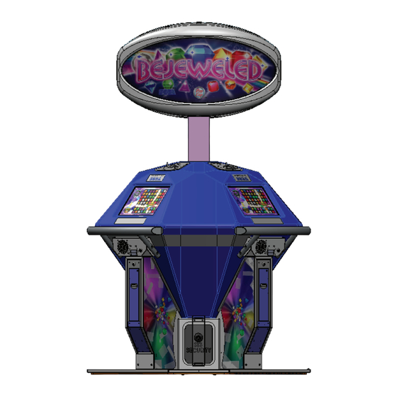
PART DESCRIPTIONS Assy Billboard Jewel Body Coin Acceptor Touch Screen Arm Rest Bill Acceptor (Option) Ticket Dispenser Assy Coin Tower Cash Box Spine Rear Door Assy Floor Assy AC Unit... -
Page 22: Accessories
ACCESSORIES Confirm that the accessories listed in the table below are present when setting up the product. Accessories marked “Spare” in the note column are consumable items but included as spares. DESCRIPTION: OWNER’S MANUAL Part No. (Qty.): 420-0014UK(1) Parts not labeled with part numbers are as yet unregistered or cannot be registered. - Page 23 ASSY SEAT KIT (BE5000-02UK) QTY (2) Brkt Seat BE-5023UK (2) M8x20 (3) M8x35 (6) M8x30 (2) Assy Seat BE-5000-02UK (2) / Assy Seat Base BE-5000-02UK (2) For installation refer to chapter 6 of this manual...
-
Page 24: Assembly And Installation
ASSEMBLY AND INSTALLATION • Perform assembly work by following the procedure herein stated. Failure to comply with the instructions can cause electric shock. • Perform assembly as per this manual. Since this is a complex machine, incorrect assembling can cause an electric shock, machine damage and/or improper functioning as per specified performance. - Page 25 • Only qualified maintenence personnel should perform such work as cabinet installation. Having untrained or unqualified personnel performing such tasks may result in either damage to the product or personal injury. Tools required for installation Step or Ladders - Aid in fixing Billboard and Billboard Panel. - Gain access to Redemption Tower...
-
Page 26: Installing Seats (Optional)
6-1 INSTALLING SEATS (OPTIONAL) • Each Seat weighs approximately 15kg. Have at least 2 people during this operation. Working alone could result in personal injuries, etc. Fit the SEAT RETAINING BKT to the lower section of each REDEMPTION TOWER as shown and loosely secure using 2x M8x35 BH SKT SC for each BKT. - Page 27 Remove the M4x20 SEC TRX (3) Screws from the loger edge of the cabinet floor trim. Offer the Seat to the cabinet. Tilt the cabinet back slightly to create a small gap to enable the seat to slide underneath. Once in position the seat will self locate.
- Page 28 Open the SERVICE DOOR to the REDEMPTION TOWER and remove the TICKET HOLDER. Located the (2) fixing points in the centre of the floor and secure loosely using (2) M8x35 BUTTON HEAD SOCKET CAP. Do not tighten at this point. Remove the TICKET HOLDER Loosely fix using (2) M8x35 BH SKT CAP Fit (2) M8x35 BUTTON HEAD SOCKET CAP to the remaining fixing points on the SEAT RETAINING...
- Page 29 Fit (2) M8x35 BUTTON HEAD SOCKET CAP to the remaining fixing points on the SEAT RETAINING BKT and tighten. Tighten the remaining bolts from the previous steps.
-
Page 30: Installing The Billboard
INSTALLING THE BILLBOARD • Billboard weighs approximately 10 kg. Have at least 2 people during this operation. Working alone could result in personal injuries, etc. • To perform work safely and securely, be sure to prepare a step which is in a safe and stable condition. - Page 31 Carefully place the rear section of the Billboard over the spine of the cabinet takeing care as to not trap any wires in the procces.. Cabinet Spine From the rear of the cabinet secure the Billboard in place by fixing the 3x M8x30 Internal Hex Socket Screws as shown.
- Page 32 Connect the Billboard to the top of the spine, making sure that the connection is made correctly. Make connection Using a step or ladder, replace the Billboard cover and refit the 10x M4 security fixings along the upper and lower sections. Billboard Cover...
-
Page 33: Installing The Stability Bkt
INSTALLING THE STABILITY BKT • When operatin a cabinet in 2 player mode it is important to keep the cabinet stable whilst at location. Therefore a STABILITY BKT MUST be installed to provide safe operation. If the STABILITY BKT is not installed the cabinet may become unstable and in extreem cases fall to the ground. - Page 34 Apply the “WIN TICKET” stickers to the cabinet. Win Ticket Sticker (Spine x1) Win Ticket Sticker (Cabi x 2)
-
Page 35: Installing A 4 Player Cabinet
INSTALLING A 4 PLAYER CABINET • Only qualified maintenence personnel should perform such work as cabinet installation. Having untrained or unqualified personnel performing such tasks may result in either damage to the product or personal injury. • Handle molded parts with care. Excessive weight or pressure may cause them to break and the broken pieces may cause injury. - Page 36 Using a Phillips No1 screwdriver remove the single screw which secures the AC unit covers to the floor from both cabinets. AC Unit Cover M4x16 M SCR PH Remove AC Unit cover from both cabinets Attach the ASSY LAN Cable (supplied) and WH Billboard Sync (supplied) to the ports on the AC Unit on both cabinets.
- Page 37 Using a Phillips No1 screwdriver and M4x10 M SCR TH CRM (16) - fit the CLOSER GAP 4P BKT (2) and the BKT FLOOR JOINT (2) CLOSER GAP 4P BKT (2) BKT FLOOR JOINT (2) Refit the AC UNIT COVER on both cabinet. AC Unit Cover...
- Page 38 At the central mid-section point of the cabinet, fit and secure both cabinets together using M5x16 Hex Blt (2) M5x16 HEX BLT Apply the “WIN TICKET” stickers to the cabinet. Win Ticket Sticker (Spine x2) Win Ticket Sticker (Cabi x 4) Using 2 or more people, carefully position the cabinet into its desired position.
-
Page 39: Installing Tickets
INSTALLING TICKETS • Only qualified Service / Maintenance Personnel are advised to change the tickets within the Redemption Tower. Having someone who is unqualified to carry out this operation may result in malfunctioning of equipment or possible injury. Using the Service key (J9117) supplied, unlock and open the door to the Redemption Tower. Service Key and Lock Locate the Ticket Holder and remove. - Page 40 Place tickets into the Ticket Holder - Do not fill past the “HI” level a this may encourage ticket jam error. Ticket Full level Place the Ticket Holder back into the Redemption tower making sure that the Ticket Low Level Switch is engaged.
- Page 41 When feeding the tickets into the Dispenser make sure that the Tickets pass through the Ticket Sensor. Lift the Roller Tab and continue to feed the Tickets underneath the roller and out through the Ticket access in the Ticket door. Once the ticket is visible at the otherside of the door, lower the Roller Guide. Sensor Raise Tab to feed ticket underneath the Roller.
-
Page 42: Fixation To Site
FIXATION TO SITE • Make sure that all the adjusters contact the floor. Otherwise the cabinet could move, causing an accident. • Provide a ventilation space at least 20cm wide behind the cabinet. There are ventilation holes on the back of the cabinet. Do not block the ventilation holes. Doing so could trap heat inside resulting in fire. -
Page 43: Power Supply And Other Connections
POWER SUPPLY AND OTHER CONNECTIONS • Use the power supply equipped with an earth leakage breaker. Use of power supply without such a breaker could result in fire if there is a current leakage. • Have available a securely grounded indoor ground terminal. Without proper grounding, customers could be electrocuted and product operations might not always be stable. -
Page 44: Turning On The Power
Fully insert the power cord connector on the side opposite the power plug into the AC unit IEC inlet. Insert the power cord plug into the outlet. The power code is laid out indoors. Protect the power cord by attaching wire cover to it. WIRE COVER TURNING ON THE POWER Set the main switch of the AC unit to ON and engage the power. - Page 45 COMPONENTS WHICH CHANGE STATE WHEN POWER IS APPLIED Billboard will illuminate Outer Billboard will illuminate Screens will show attract mode Audio Output Jewel will illuminate...
-
Page 46: Confirmation Of Assembly
CONFIRMATION OF ASSEMBLY In the test mode, ascertain that the assembly has been made correctly and IC Board is satisfactory. In the test mode, perform the following test: (refer to chapter 9). 9-4 INPUT TEST This menu is used to test the system inputs such as steering, pedals and buttons. To implement the test, press each device that is listed and check the results on screen. -
Page 47: Applying Warning Labels (Epileptiform Seizures)
6-10 APPLYING WARNING LABELS (EPILEPTIFORM SEIZURES) • The operator MUST apply the Epileptiform Seizure Label to this product. Failing to apply this label may result in the player/observer suffering from a photosensitive seizure. Warning the potential player/ observer of this before the start of a game may prevent such accidents. -
Page 48: Precautions When Moving The Machine
PRECAUTIONS WHEN MOVING THE MACHINE • Always disconnect the power cable before moving the product. If it is moved with the power cable connected, the cable could be damaged, causing fire or electric shock. • To move the unit over the floor, always use a trolley, truck or another form of lifting apparatus. -
Page 49: Game Description
For anyone new to the Bejeweled phenomenon it couldn’t be any easier to pick up and play. Just swap adjacent gems with one another to create lines of 3 of the same kind. Bonuses are awarded for creating lines of 4 and 5 gems. -
Page 50: Help
Help HELP Pressing the HELP button will take you to a “HOW TO PLAY” screen. -
Page 51: High Score Tables
This screen details the scoring system for the game. The top section lists the type and required amount of ‘Gem Matches’ to win a predetermined Ticket value as well as the score required to win the Jackpot Ticket value(please see Test Menu - Ticket Payout Settings for more information). The bottom section is split into 3 boxes and explains how ‘Time Gems’... - Page 52 The player will be asked to enter their initials and then press the DONE button. There is a 10 second time limit to enter initials, and provided they meet the criteria, will be used in game and in the High Score table if the player scores enough points.
- Page 53 It is at this point the player can choose a Single Player game by pressing PRESS HERE FOR SINGLE PLAYER. If the maximum amount of players joins a Multiplayer game will begin automatically. This is dependant of the cabinet configuration. (2 Player configuration shown above). If the timer reaches 0 (zero) and another player has not joined a Single Player game will begin.
-
Page 54: Single Game Play
SINGLE GAME PLAY Each game starts with 1 minute on the clock How to play • Player enters their initials using on-screen keyboard • Player enters multiplayer “lobby” with option to drop out to single player game • 1:00 minute game time is awarded and game begins • Unlimited “hints”... - Page 55 o A Star Gem, a shining gem with a four-pointed star in the middle, forms when a player makes a “T”, “+” or “L” shape. When matched, it explodes every gem in its row and column o A Hypercube is formed by matching five gems in a row. When swapped with another gem, it detonates every gem of that colour.
-
Page 56: Explanation Of Test And Data Display
EXPLANATION OF TEST AND DATA DISPLAY Perform tests and data checks periodically by manipulating the TEST Button and SERVICE Button in the cabinet. Follow the instructions in this chapter to conduct checks when the game machine is first installed, when money is being collected, or when the game machine does not operate properly. -
Page 57: Switch Unit And Coin Meter
9-1 SWITCH UNIT AND COIN METER. The SWITCH UNIT and COUNTERS are housed within the REDEMPTION TOWER. To access these controls you will need to open the TICKET door, the switches and counters can be found at the base of the outer door. DEVICE FUNCTION TEST BUTTON Press to enter TEST MODE - Also used to enter choices selected within TEST MODE... - Page 58 TEST MENU Press the physical TEST button to open the TEST MENU. The following options are available from the Test Menu. Use the physical or ON screen SERVICE button to move the cursor to the desired test item. Press the physical or ON screen TEST button to enter the selected item. SYSTEM INFORMATION General information on Software.
-
Page 59: System Information
9-3 SYSTEM INFORMATION Select ‘System Information’ from the Test Menu to display the System Information menu. The System Information Test lists revision numbers and names of currently installed system components. DISK IMAGE VERSION Version number for the master hard disk image LAUNCHER VERSION Version number of System Launcher program SHELL VERSION... -
Page 60: Input Test
9-4 INPUT TEST Select ‘Input Test’ from the Test Menu screen to display the Input Test menu. This screen is used to test the system inputs such as the Ticket notch and Coin input. To implement the test, operate each device listed and check the results on screen. When activated and detected by the system the result on screen will be ON. -
Page 61: Output Test
9-5 OUTPUT TEST Select ‘Output Test’ from the Game Test Mode to display the Output Test Menu. This test is used to check all configured outputs from the IO board. Use the SERVICE button to move the cursor to the desired test item. Press the TEST button to test the selected item. -
Page 62: Network Test
9-6 NETWORK TEST Select ‘NETWORK TEST’ from the Test Menu to display Network Test menu. NETWORK STATUS ON if network hardware is OK, OFF if network is not on CABINETS CONNECTED The number of cabinets connected INCLUDING the current one CABINET TYPE TWO PLAYER or FOUR PLAYER CABINET ID... -
Page 63: Coin Test
9-7 COIN TEST Select ‘COIN TEST’ from the Test Menu screen to display the Coin Test screen. COIN COUNT Coin Count value from IO board (can not reset) CREDITS Total number of Coin credits added to the system SERVICE CREDITS Total number of Service Credits added to the system FREEPLAY ON –... -
Page 64: Sound Test
9-8 SOUND TEST Select ‘SOUND TEST’ from the Test Mode to display the Sound Test screen. This test is used to test the function of the speakers and set audio levels for the Game. AUDIO IN ATTRACT ON – sound will be played in Attract mode OFF –... -
Page 65: Screen Test
9-9 SCREEN TEST Select ‘SCREEN TEST’ from the Test Mode to display the Screen Test screen. This test is used to display various test patterns for the display screen. COLOUR BARS Displays vertical colour bars for colour balance correction BRIGHTNESS Displays graduated greyscale for brightness adjustment GRID ALIGNMENT Displays grid for screen size and alignment... -
Page 66: Touchscreen Test
9-10 TOUCHSCREEN TEST Select ‘TOUCHSCREEN TEST’ from the Test Mode to display the Touchscreen Test screen. This test is used to calibrate the touchscreen to ensure reliable and accurate game play. The calibration procedure requires you to TOUCH and then RELEASE 3 targets on the touchscreen, finally dragging the cursor around the screen to test the positioning. -
Page 67: Bookkeeping Test
9-11 BOOKKEEPING TEST Select ‘BOOKKEEPING’ from the Test Mode to display the Bookkeeping Test screen. This test is used to review statistical data from the system. It consists of 4 screens of data. BOOKKEEPING PAGE 1 This page displays an overview of the coins and credits data. TOTAL PLAYS The total numbers of games played AVERAGE GAME TIME... - Page 68 BOOKKEEPING PAGE 2 This page displays a breakdown of the games based on if it was a single player or multiplayer game, and ticket and jackpot details. 1 PLAYER GAMES Displays the number of1 player games based on TOTAL PLAYS 2 PLAYER GAMES Displays the number of2 player games based on TOTAL PLAYS 3 PLAYER GAMES...
- Page 69 BOOKKEEPING PAGE 3 This page displays breakdown of the games on individual days. This is a cumulative total from the last point in time that the Bookkeeping was cleared. PLAY ON SUNDAY Total games played on a Sunday PLAY ON MONDAY Total games played on a Monday PLAY ON TUESDAY Total games played on a Tuesday...
- Page 70 BOOKKEEPING PAGE 4 This page displays a breakdown of the games into hourly periods. This is a cumulative total from the last point in time that the Bookkeeping was cleared. Each hour is logged separately in 24 hour format therefore 1-01 logs games between 12am and 1am 1-02 logs games between 1am and 2am.
-
Page 71: Clock Settings
9-12 CLOCK SETTINGS Select ‘CLOCK SETTING’ from the Test Menu screen to enter the Clock Setting screen. This screen is used to set the time and date of the system. CURRENT TIME Shows the current time. Displayed in 24 hour clock format HH:MM:SS CURRENT DATE Shows the current date. -
Page 72: Game Settings
9-13 GAME SETTINGS Select ‘GAME SETTINGS’ from the Test Menu screen to enter the Game Settings screen. This test is used to change the language of the in game text. NOTE TEST MENU text only displays in ENGLISH. The following option is available from the Game Settings screen LANGUAGE Options available English, French, German, Spanish, Russian and Turkish... -
Page 73: Ticket Payout Settings
9-14 TICKET PAYOUT SETTINGS Select ‘TICKET PAYOUT SETTINGS’ from the Test Menu screen to enter the Ticket Payout Settings screen. This test is used to change the percentage payout settings for the game, as well as enabling/disabling Mercy and Multiplayer Bonus Tickets. TICKETS PER GAME This value will automatically change based on the settings assigned below... -
Page 74: Periodic Inspection
PERIODIC INSPECTION The items listed below require periodic check and maintenance to retain the performance of this machine and to ensure safe business operation. When handling the controller, the player will be in direct contact with it. In order to always allow the player to enjoy the game, be sure to clean it regularly. - Page 75 Cleaning the Cabinet Surfaces When the cabinet surfaces are badly soiled, remove stains with a soft cloth dipped in water or diluted with a chemical detergent and squeezed dry. To avoid damaging surface finish, do not use such solvents as thinner, benzine, etc. other than ethyl alcohol, or abrasives, bleaching agent and chemical dustcloth. Some general-purpose household, kitchen and furniture cleaning products may contain strong solvents that degrade plastic components, coatings, and print.
-
Page 76: Troubleshooting
TROUBLESHOOTING 11-1 TROUBLESHOOTING (WHEN NO ERROR MESSAGE IS SHOWN) • In order to prevent electric shock and short circuit, be sure to turn power off before performing work. • Be careful so as not to damage wirings. Damaged wiring can cause electric shock or short circuit. •... - Page 77 If a problem occurs, first check to make sure that the wiring connectors are properly connected. 11 TABLE 01 PROBLEM CAUSE COUNTERMEASURES When the main SW is The power is not ON. Firmly insert the plug into the outlet. turned ON, the machine Incorrect power source/voltage.
- Page 78 Replacing Fuses • In case fuse replacements other than those stated in this manual are necessary, contact where you purchased the product from for inquiries regarding this matter. • In order to prevent an electric shock, be sure to turn power off and unplug from the socket outlet before performing work by touching the internal parts of the product.
-
Page 79: Design-Related Parts
DESIGN-RELATED PARTS For the warning display stickers, refer to Section 1. HEADER INSERT (BE-0505UK) BILLBOARD HEADER (BE-0502UK) SPINE STICKER (BE-0011UK) SEGA STICKER POPCAP STICKER (BE-1011-CUK) (BE-1011-DUK) MAIN JEWEL WIN TKT STICKER (BE-1011-AUK) (BE-0503UK) FRONT LONG STICKER (BE-0313UK) BOX L STICKER... -
Page 80: Parts List
PARTS LIST ASSY TOP BEJEWELED 2P STRUCTURE... - Page 81 1 ASSY TOP BEJEWELED 2P TICKET (BE-0000UK) (D-1/2) ITEM NO PART NO DESCRIPTION BE-0300UK ASSY REDEMPTION TOWER BE-0500UK ASSY BILLBOARD BE-1000UK ASSY MAIN CABI BE-0005UK ARMREST BE-0006UK PLATE BLANK TOWER 421-7988-91UK STICKER SERIAL NUMBER UK 421-7020UK STICKER CAUTION FORK 440-CS0186UK...
- Page 82 1 ASSY TOP BEJEWELED 2P TICKET (BE-0000UK) (D-2/2)
- Page 83 2 ASSY REDEMPTION TOWER (BE-0300UK) (D-1/2) ITEM PART NO DESCRIPTION BE-0301UK BOX ENCLOSURE REDEMPTION BE-0302UK BRKT METER SW VOL BD BE-0303UK DECAL BOX SIDE L ***1 BE-0303-AUK DECAL BOX SIDE L BLANK BE-0304UK DECAL BOX SIDE R ***1 BE-0304-AUK DECAL BOX SIDE R BLANK BE-0305UK FLAP REJECT BE-0306UK...
- Page 84 2 ASSY REDEMPTION TOWER (BE-0300UK) (D-2/2) 204 205...
- Page 85 3 ASSY MAIN CABINET (BE-1000UK) (D-1/3)
- Page 86 3 ASSY MIN CABINET (BE-1000UK) (D-2/3) ITEM NO PART NO DESCRIPTION BE-1100UK ASSY SUB STRUCTURE BE-1200UK ASSY LCD MONITOR BE-1300UK ASSY COIN ENTRY BE-1400UK ASSY AC UNIT BE-4100UK ASSY DOOR BACK BE-1011UK MAIN JEWEL FORMING BE-1001UK CHUTE REJECT/CASHBOX **10 BE-1002UK CASH BOX **11 BE-1003UK...
- Page 87 3 ASSY MIN CABINET (BE-1000UK) (D-3/3) ITEM NO PART NO DESCRIPTION **301 BE-60002UK WH AC DISTRIBUTION **302 BE-60003UK WH AC BB STRUT **303 BE-60012UK WH SPKR B EXTN **304 BE-60013UK WH I/O EXTN **305 BE-60014UK WH DC POWER A **306 BE-60017UK WH AC LCD PSU **307...
- Page 88 4 ASSY MAIN JEWEL FORMING (BE-1011UK) (D-1/1) ITEM NO PART NO DESCRIPTION BE-1011-AUK MAIN JEWEL FORMING BLANK BE-1011-BUK PLATE COIN ENTRY SURROUND BE-1011-CUK LOGO SEGA AMUSEMENTS **201 050-F00400 M4 NUT FLG SER PAS **202 068-441616 M4 WSHR 16OD FLT PAS...
- Page 89 5 ASSY SUB STRUCTURE (BE-1100UK) (D-1/2) ITEM NO PART NO ***1 BE-1101UK BASE FLOOR ***2 BE-1102UK ENCLOSURE CASHBOX ***3 BE-1103UK SPINE MAIN ***4 BE-1104UK BACK FRAME WOOD ***5 BE-1105UK BRACE VERT ***6 BE-1106UK BRACE HORIZ ***7 BE-1107UK BRACE HORIZ SHORT ***8 BE-1108UK BRACE MONITOR...
- Page 90 5 ASSY SUB STRUCTURE (BE-1100UK) (D-2/2) ITEM NO PART NO DESCRIPTION ***201 020-F00860-0Z M8X60 SKT CSK OZ ***202 030-000816 M8X16 BLT PAS ***203 060-S00800 M8 WSHR SPR PAS ***204 068-852216 M8 WSHR 22OD FLT PAS ***205 020-F00830-0Z M8X30 SKT CSK OZ ***206 050-F00500 M5 NUT FLG SER PAS...
- Page 91 6 ASSY LCD MONITOR (BE-1200UK) (D-1/1) ITEM NO PART NO DESCRIPTION ***1 BE-1201UK BRKT MON MOUNT ***2 SHIM ***101 200-6015-01TUK LCD 15” TOUCH ***201 000-P00408 M4X8 MSCR PAN PAS ***202 060-S00400 M4 WSHR SPR PAS ***203 060-F00400 M4 WSHR FORM A FLT PAS...
- Page 92 7 ASSY COIN ENTRY (BE-1300UK) (D-1/1) ITEM NO PART NO DESCRIPTION ***1 BE-1301UK PLATE COIN ENTRY ***2 BE-1302UK CRADLE MECH ***101 220-5610-01 COIN MECH SR3 ***102 EP1380-01 EXCEL CREDIT BOARD ***103 220-0002UK BEZEL TOP C ENTRY 3MM 107-0040 ***104 220-5086-CUK MECH CLIP ***105 220-5575UK...
- Page 93 8 ASSY AC UNIT (BE-1400UK) (D-1/1) ITEM NO PART NO DESCRIPTION ***1 BE-1401UK PLATE AC MOUNT ***2 TFF-0402UK CONN COVER ***101 EP1391 COUPLER INLINE LAN RJ45 ***102 EP1423 IEC INLET/OUTLET 211-1017 ***103 SW1109 SW ROCKER ***104 EP1419 FILTER SCHAFFNER 2030-16-06 ***201 050-F00400 M4 NUT FLG SER PAS...
- Page 94 9 ASSY BACK DOOR (BE-4100UK) (D-1/1) ITEM NO PART NO DESCRIPTION ***1 BE-4101UK DOOR BACK ***101 610-0008-01UK ASSY PC FUJITSU D3003-S ***102 EP2005-00PI DK BESTD EU PINK ***103 220-5575UK LOCK (J9117) KEY TO LIKE 22MM W CAM ***104 ORP-2372UK CAM CRKD 9 L34 BATON 690-ZB34 ***105 838-8001UK AUDIO AMP2.2 VISATON 7100...
-
Page 95: Wire Colour Code Table
WIRE COLOUR CODE TABLE The DC power wire color for this product is different from previous SEGA titles. Working from the previous wire colors will create a high risk of fire. The color codes for the wires used in the diagrams in the following chapter are as follows. PINK SKY BLUE BROWN PURPLE LIGHT GREEN Wires other than those of any of the above 5 single colors will be displayed by 2 alphanumeric characters. BLUE... -
Page 96: Wiring Diagrams
(D-1/3) WIRING DIAGRAMS... - Page 97 (D-2/3)...
- Page 98 (D-3/3)...
Need help?
Do you have a question about the BEJEWELED and is the answer not in the manual?
Questions and answers