Table of Contents
Advertisement
1
st
PRINTING
April 2021
Sega Amusements International Limited.
42 Barwell Business Park, Leatherhead Road, Chessington, Surrey, KT9 2NY. United Kingdom.
Telephone: +44 (0) 208 391 8090
Facsimile:
+44 (0) 208 391 8099
email: sales@segaarcade.com
Web: http://www.segaarcade.com
© SEGA
Errors and omissions excepted (E&OE)
OWNER'S & SERVICE MANUAL
IMPORTANT
• Before using this product, read this manual carefully to understand the
contents herein stated.
• After reading this manual, be sure to keep it near the product or in a
convenient place for easy reference when necessary.
Advertisement
Table of Contents

Related Manuals for Sega MISSION IMPOSSIBLE ARCADE


Summary of Contents for Sega MISSION IMPOSSIBLE ARCADE
- Page 1 PRINTING April 2021 OWNER’S & SERVICE MANUAL Sega Amusements International Limited. 42 Barwell Business Park, Leatherhead Road, Chessington, Surrey, KT9 2NY. United Kingdom. Telephone: +44 (0) 208 391 8090 Facsimile: +44 (0) 208 391 8099 email: sales@segaarcade.com Web: http://www.segaarcade.com © SEGA IMPORTANT •...
- Page 2 BEFORE USING THE PRODUCT , BE SURE TO READ THE FOLLOWING: To maintain safety: To ensure the safe operation of this product, be sure to read the following before usage. The following instructions are intended for the users, operators and the personnel in charge of the operation of the product.
- Page 3 INSPECTIONS IMMEDIATELY AFTER TRANSPORTING THE PRODUCT TO THE LOCATION Normally, at the time of shipment, SEGA products are in a status allowing for usage immediately after transporting to the location. Nevertheless, an irregular situation may occur during transportation. Before turning on the power, check the following points to ensure that the product has been transported in a satisfactory status.
- Page 4 LIST OF THIRD PARTY RIGHTS / LICENCING _____________________________________________ Copyright (C) 1994-2008 Lua.org, PUC-Rio. Permission is hereby granted, free of charge, to any person obtaining a copy of this software and associated documentation files (the “Software”), to deal in the Software without restriction, including without limitation the rights to use, copy, modify, merge, publish, distribute, sublicense, and/or sell copies of the Software, and to permit persons to whom the Software is furnished to do so, subject to the following conditions: The above copyright notice and this permission notice shall be included in all copies or substantial portions of the Software.
-
Page 5: Introduction
Indicates a warning or caution that, if ignored, may result in the mishandling of the product and cause faulty operation or damage to the product. Sega Amusements International Limited. 42 Barwell Business Park, Leatherhead Road, Chessington, Surrey, KT9 2NY. United Kingdom. - Page 6 Definition of 'Site Maintenance Personnel or Other Qualified Individuals Definition of 'Site Maintenance Personnel or Other Qualified Individuals Servicing and maintenance work of the contents herein stated should be performed by the SERVICEMAN stipulated as per IEC Standard. Those who do not have technical expertise and knowledge other than the SERVICEMAN are not allowed to perform the work herein stated.
- Page 7 Electrical & Mechanical Specifications Electrical & Mechanical Specifications SPECIFICATIONS Individual Dimensions Single Monitor Cabinet: 1.95m (76.8in) [width] x 1.10m (43.3in) [depth] 2.77m (109.0in) [height] Assembled Floor: 1.88m (74.0in) [width] x 2.10m (82.6in) [depth] 0.154m (6.06in) [height] Filly Assembled Dimensions: 4m (157.5in) [width] x 2.61m (102.7in) [depth] 2.86m (112.6in.) [height] Weights Monitor Cabinet: 1...
- Page 8 The symbol shown below will be placed on all products manufactured from 13th August 2005, which indicates this product must NOT be disposed of with other normal waste. Upon purchasing any EEE from SEGA Amusements International Ltd. The user accepts responsibility to dispose of their waste equipment by arranging to return it to a designated UK collection point (AATF) or an Approved Exporter (AE) for the correct recycling of waste electrical and electronic equipment.
- Page 9 Photosensitive Epilepsy Photosensitive Epilepsy For about 3 percent of people with epilepsy, exposure to flashing lights at certain intensities or to certain visual patterns can trigger seizures. This condition is known as photosensitive epilepsy. Please be sure to warn players and spectators by applying the Epilepsy warning in the language suitable for point of operation.
-
Page 10: Table Of Contents
TABLE OF CONTENTS INTRODUCTION HANDLING PRECAUTIONS PRECAUTIONS REGARDING INSTALLATION LOCATION 2-1 LIMITATIONS OF USAGE 2-2 OPERATION AREA PRECAUTIONS REGARDING PRODUCT OPERATION 3-1 BEFORE OPERATION 3-2 DURING OPERATION (PAYING ATTENTION TO CUSTOMERS) PART DESCRIPTIONS ACCESSORIES ASSEMBLY AND INSTALLATION 6-1 INSTALLATION KIT 6-2 ASSEMBLY 6-3 INSPECT FIXATION TO SITE 6-6 POWER SUPPLY AND OTHER CONNECTIONS... - Page 11 11-2 CLEANING THE SCREEN 11-3 ON SCREEN ADJUSTMENT METHOD (OSD) COIN HANDLING 12-1 CLEANING THE COIN ACCEPTOR MECHANICAL 12-2 FAULT FINDING 12-3 SWITCH PLATE - SINGLE CABI (EXCEL) 12-4 COIN REGION & PRICE OF PLAY SETTINGS 12-5 PRICE OF PLAY QUICK START - USA LIGHTS AND LIGHTING 13-1 LED LIGHTING - FLOOR 13-2 LED LIGHTING - STEP...
-
Page 12: Handling Precautions
• SEGA shall not be held responsible for damage, compensation for damage to a third party, caused by specification changes not designated by SEGA. - Page 13 Some parts are not designed and manufactured specifically for this game machine. The manufacturers may discontinue, or change the specifications of such general-purpose parts. If this is the case, SEGA cannot repair or replace a failed game machine whether or not a warranty period has expired.
- Page 14 VIDEO GAME-INDUCED SEIZURES (VGS) AND PHOTOSENSETIVE EPILEPSY (PSE) This SEGA product has warning displays on stickers which outline the risk of epilepticform and photosensetive seizures. These warning displays on stickers are applied close in proximity of the device which may promote symptoms of either video game-induced seizures or epilepsy.
- Page 15 440-WS0010UK Warning Sticker CAUTION 440-CS0010UK Caution Sticker Take care when servicing within these areas. 440-CS0010UK CAUTION Take care when servicing within these areas. 440-CS0010UK 440-DS0010UK Danger Sticker - High Voltage CAUTION DANGER OF EXPLOSION IF BATTERY IS INCORRECTLY REPLACED. Replace only with the same or equivalent type recommended by the manufacturer.
- Page 16 440-WS0100UK FORK HERE CAUTION PHOTOSENSITIVE SEIZURE (PSE) If you or your child has experienced a convulsive attack, loss of consciousness, etc., due to light stimuli or TV game, or fear that you may experience such symptoms, be very careful of using this machine.
-
Page 17: Precautions Regarding Installation Location
Securing a safe area for operation as described in this manual will ensure safe operation for players and observers. SEGA shall not be held responsible for damage or compensation for damage to a third party, resulting from the failure to observe this instruction. -
Page 18: Limitations Of Usage
LIMITATIONS OF USAGE Be sure to check the Electrical Specifications. Ensure that this product is compatible with the location's power supply, voltage, and frequency requirements. A label describing Electrical Specifications is attached to the product. Non-compliance with the Electrical Specifications can cause a fire and electric shock. -
Page 19: Operation Area
It can cause generation of heat which in turn may cause a fire hazard. • SEGA shall not be held responsible for damage or compensation for damage to a third party, resulting from the failure to observe this instruction. - Page 20 Securing a safe area for operation as described in this manual will ensure safe operation for players and observers. SEGA shall not be held responsible for damage or compensation for damage to a third party, resulting from the failure to observe these instructions.
-
Page 21: Precautions Regarding Product Operation
PRECAUTIONS REGARDING PRODUCT OPERATION In order to prevent accidents and inappropriate behaviour, please check the following before operating the product. BEFORE OPERATION • To ensure maximum safety for the players and the customers, ensure that where the product is operated has sufficient lighting to allow any warnings to be read. - Page 22 • During daily cleaning, be sure to check the surface of the controllers and other parts that the player touches with his hands for damage, cracks, or loose screws. If a player uses the machine while it is damaged, cracked, or has a loose screw, the player may become injured.
-
Page 23: During Operation (Paying Attention To Customers)
DURING OPERATION (PAYING ATTENTION TO CUSTOMERS) In order to prevent an accident or encourage inappropriate behaviour, the attendant or operator must endeavor to always pay attention to the behaviour of the players and customers. To play this machine involves physical activity undertaken by the player . - Page 24 In order to avoid accidents, check the following before starting the operation: • To ensure maximum safety for the players and the customers, ensure that where the product is operated has sufficient lighting to allow any warnings to be read. Operation under insufficient lighting can cause bodily contact with each other, hitting accident, and/or trouble between customers.
- Page 25 • Do not use the cabinet as a walk-through as a means to get to another area within the same location. Do not allow pedestrians to unnecessarily walk through the cabinet whilst in use. Allowing too many people within the playing area may cause trip hazards and injury.
-
Page 26: Part Descriptions
PART DESCRIPTIONS Assy Dual Controllers Assy Lit Header Assy LCD Display Assy Billboard Assy Side Screen Poster Cover Speakers (Woofer) Playing area Assy Controller Cabi Assy Step Assy Arc LED Assy Floor ASSY MAIN CABI Speakers Camera Assy Control Panel Locking Clasps (Optional) -
Page 27: Accessories
ACCESSORIES Confirm that the accessories listed in the table below are present when setting up the product. Accessories marked “Spare” in the note column are consumable items but included as spares. Parts not labeled with part numbers are yet to be assigned. Be sure to handle all parts with care, as some parts are not available for purchase separately. -
Page 28: Assembly And Installation
ASSEMBLY AND INSTALLATION • Perform assembly work by following the procedure herein stated. Failure to comply with the instructions can cause electric shock. • Perform assembling as per this manual. Since this is a complex machine, incorrect assembling can cause an electric shock, machine damage and/or improper functioning as per specified performance. - Page 29 • For the sake of safety, use the main power cords provided. If a main power cord is damaged, it must be replaced by the manufacturer, a recognised distributor or a qualified engineer to avoid any hazard. • When inserting or removing a connector, always hold it by its main part. If you hold it by anything else while doing so, the connections between wire and connector terminal fixtures could be damaged;...
- Page 30 TOOLS NECESSARY FOR WORK Phillips Screwdriver Torx T20 Security Driver Spanner / Adjustable spanner (24mm) Key Master Step or Stool Socket Wrench (13mm) Hex Key for 4mm, 8mm, 10mm & 13mm fixings.
- Page 31 Servicing and maintenance work of the contents herein stated should be performed by the SERVICEMAN stipulated as per IEC Standard. Those who do not have technical expertise and knowledge other than the SERVICEMAN are not allowed to perform the work herein stated. Executing aforementioned work by such non-technical personnel can cause serious accidents that may endanger life.
-
Page 32: Installation Kit
SDX. Please check all the items that are listed are present and free from damage. In the unlikely event of identifying either missing or damaged parts, please contact your point of purchase or call the SEGA Customer Service team who will deal directly with your complaint. - Page 33 This section highlights the different components contained within the INSTALLATION KIT *401 ASSY INST MT TNX SDX (MI-INST-TNX-SDX) **1 ASSY STEP L TNX x2 **2 ASSY STEP R TNX x2 (MI-0200XUK) (MI-0250XUK) **4 ASSY FLOOR TNX L (MI-0400XUK) **5 ASSY FLOOR TNX R (MI-0430XUK) **6 ASSY BILLBOARD SDX TEAM BETA (MI-00500UK)
- Page 34 **7 ASSY ROOF TNX OUTER x2 **8 ASSY ROOF TNX INNER x2 (MI-0800XUK) (MI-0830XUK) **9 ASSY ROOF CURVE TNX L x2 (MI-0850XUK) **10 ASSY ROOF CURVE TNX R x2 (MI-0870XUK) **11 ASSY LIGHT OUTER CHEEK L x2 (MI-1400UK) **12 ASSY LIGHT OUTER CHEEK R x2 (MI-1450UK)
- Page 35 **13 ASSY SIDE SCREEN L BLUE (MI-1700XUK) **14 ASSY SIDE SCREEN R BLUE (MI-1750XUK) **22 ASSY SIDE SCREEN L RED (MI-1720XUK) **23 ASSY SIDE SCEEN R RED (MI-1770XUK)
- Page 36 **15 ROOF SUPPORT MAIN TNX L x2 (MI-0011XUK) **16 ROOF SUPPORT MAIN TNX R x2 (MI-0012XUK) **17 BKT ROOF SUPPORT TNX CENTRE LOCK x2 (MI-0013XUK) **18 BKT ROOF CURVE TNX COVER x6 (MI-0014-01UK) **19 CROSSBEAM ROOF SUPPORT x3 (MI-0015UK) **35 PLATE JOINT FLOORS TNX CENTRE (MI-0031XUK)
- Page 37 **36 PLATE JOINT FLOOR MON CABI x4 (MI-0032UK) **37 BKT JOINT FLOOR MON CABI UNDER x4 (MI-0033UK) **38 BKT JOINT STEP x4 (MI-0034UK) **64 ASSY POSTER COVER BACK DOOR UPPER BLUE (MI-1470UK) **66 ASSY POSTER COVER BACK DOOR UPPER RED (MI-1490UK) **65 POSTER EXT BACK BILLBOARD BLUE **66 POSTER EXT BACK BILLBOARD RED...
- Page 38 **73 BKT SUPPORT VERT TOP HEADER TNX x8 (MI-0073X-01UK **74 BKT SUPPORT HORIZ TOP HEADER TNX x2 (MI-0074X-01UK **80 ASSY LIT HEADER FRONT TNX (MI-0090XUK **81 ASSY LIT HEADER BACK TNX (MI-0100XUK...
- Page 39 **85 PLATE LIT HEADER TNX OUTER L x2 (MI-0095XUK) **86 PLATE LIT HEADER TNX OUTER R x2 (MI-0096XUK) **101 UK POWER LEAD 10A (LM1227) **102 EU POWER LEAD 10A (LM1246) **101 US POWER LEAD IEC (LM1500UK)
- Page 40 6-1-1 FIXINGS Below is a list of fixings which are need during the Installation of MISSION IMPOSSIBLE SDX. Some fixings are already placed within their locations on specific parts. Others are placed within clear plastic bags and can be found within the Cashboxes of each MONITOR CABINET.
- Page 41 Below is a guide to identifying fixings contained within the INSTALLATION KIT **201 029-B00840 M8X40 SKT BH PAS 40mm **202 060-S00800 M8 WSHR SPR PAS Colour - Silver **203 068-852216 M8 WSHR 22OD FLT PAS Colour - Silver **204 020-F00830 M8X30 SKT CSK PAS 30mm Colour - Silver...
- Page 42 1-1-3 HARNESSES Below is a list of additional harnesses which are required to successfully install the MISSION IMPOSSIBLE SDX. Please take care when handling harnesses. Damaged harnesses can cause an electrical malfunction such as a short circuit or electrical shock. Item Description Part Number...
-
Page 43: Assembly
ASSEMBLY Perform assembly work by following the procedure herein stated. Failure to comply with the instructions can cause electric shock. Perform assembling as per this manual. Since this is a complex machine, incorrect assembling can cause an electric shock, machine damage and/or improper functioning as per specified performance. - Page 44 • For the sake of safety and workability, use 3 core coaxial CE/UL approved cables for the power cables (provided). • When inserting or removing a connector, always hold it by its main part. If you hold it by anything else while doing so, the connections between wire and connector terminal fixtures could be damaged;...
- Page 45 6-2-1 ASSEMBLING ASSY FLOOR TNX L AND ASSY FLOOR TNX R Servicing and maintenance work of the contents herein stated should be performed by the SERVICEMAN stipulated as per IEC Standard. Those who do not have technical expertise and knowledge other than the SERVICEMAN are not allowed to perform the work herein stated.
- Page 46 STOP THE FLOOR ASSY IS HEAVY. USE 2 PEOPLE WHEN ASSEMBLING/ INSTALLING. Unpack ASSY FLOOR TNX L and ASSY FLOOR TNX R taking care not to damage any harnessing. Position both FLOORS onto their CASTORS and in the position shown. **5 ASSY FLOOR TNX R [MI-0430XUK] **4 ASSY FLOOR TNX L...
- Page 47 Remove the (4) M8X30 SKT CSK PAS screws from ASSY FLOOR TNX R. Gently slide both floors together taking care not to trap and harnessing between its joints. Secure in place using the (4) M8X30 SKT CSK PAS screws. **5 ASSY FLOOR TNX R [MI-0430XUK] ***203 M8X30 SKT CSK PAS (4) [020-F00830]...
- Page 48 6-2-2 APPLYING ASSY FLOOR TNX TO ASSY MAIN CABI L & R Unscrew and remove the (8) sets of M8X40 SKT BH PAS screws along with their washers from the base of both MONITOR CABIs. **201 M8x40 SKT BH PAS (4)per Cabi [029-B00840] **202 M8 WSHR SPR PAS (4)per Cabi [060-S00800]...
- Page 49 Carefully slide both MONITOR CABIs upto the ASSY FLOOR taking care not to trap any harnesses. Once in position secure using the (8) M8X30 SKT CSK PAS screws removed from STEP 8. **204 M8x30 SKT CSK PAS (8) [029-B00840] Ensure that the product is level. Failing to make the product level may impact on fixing alignment later on in the installation process.
- Page 50 STOP At this point in the installation it is recommended that the ASSY FLOOR be checked for any electrical abnormalities. Please temporarily apply power to the Left cabinet and proceed with the OUTPUT TEST as explained in section 9-2-3 of this manual. Using the Left Hand Cabinet.
- Page 51 6-2-3 ROOF SUPPORTS Remove the (5) Sets of fixings from each of the ROOF SUPPORT MAIN L and ROOF SUPPORT MAIN R. There will be a total of 20 sets of fixings. **16 ROOF SUPPORT MAIN TNX R (2) [MI-0012UK] **15 ROOF SUPPORT MAIN TNX L (2) [MI-0011UK] **215 M8x25 SKT BH BLK (5 per)
- Page 52 Unscrew (4) M8X40 SKT BH PAS screws along with their washers from the base of both MONITOR CABIs. Apply the (2) BKT JOINT FLOOR MON CABI UNDER (taken from previous step) to each MONITOR CABI as shown. **19 CROSSBEAM ROOF SUPPORT (3) [MI-0015UK] **215 M8x25 SKT BH BLK (2 per) [029-B00825]...
- Page 53 6-2-4 ASSY BILLBOARDS STOP THE ASSY BILLBOARD IS HEAVY! DO NOT WORK ALONE. A MINIMUM OF 3 PEOPLE IS RECOMMENDED TO PERFORM THIS OPERATION. Carefully unpack both ASSY BILLBOARDs and remove the (3) sets of fixings loosley fitted to the rear and undeside of both ASSY BILLBOARDS **6 ASSY BILLBOARD SDX TEAM BETA (MI-00500UK)
- Page 54 Using a minimum of two people and ladders. Carefully lift the ASSY BILLBOARD onto the ASSY CABI. Make the connection at the rear of the ASSY BILLBOARD before placing into position. NOTE: The artwork within the ASSY BILLBOARDS are different. Please see locations below:- ASSY BILLBOARD L ASSY BILLBOARD R **6 ASSY BILLBOARD SDX TEAM BETA...
- Page 55 6-2-5 ROOF CURVE L AND R Carefully unpack (2) ASSY ROOF CURVE TNX L and (2) ASSY ROOF CURVE TNX R. Locate the 5 sets of fixings (taking note of their allocations) and remove.
- Page 56 Using a minimum of (2) people, carefully locate the first of the ROOF CURVE TNX L between the MAIN CABI L and the BKT ROOF SUPPORT CENTRE and loosely secure into position. Carefully lower the ROOF CURVE TNX L on and over the BKT ROOF SUPPORT CENTRE LOCK.
- Page 57 Using a minimum of (2) people, carefully locate the first of the ROOF CURVE TNX R between the MAIN CABI R and the BKT ROOF SUPPORT CENTRE and loosely secure into position. Raise slightly both ROOF CURVE L and ROOF CURVE R before lowering into position.
- Page 58 Follow and repeat STEPS 1, 2 and 3 in this section to attach and secure the ROOF CURVE TNX L and R on the opposite side of the cabinets. Follow previous steps to fit and attach the opposing side.
- Page 59 6-2-6 ASSY LED ARC Carefully uncoil the ASSY LED ARC [MI-6005UK]. Locate and push firmly into place along the outer face of the ROOF CURVES L and R whilst paying particular attention to the 18 clips positioned within the recess. Grip Clips **301 ASSY LED ARC **301 ASSY LED ARC...
- Page 60 Secure the ASSY LED ARC into place by fitting the (3) BKT ROOF CURVE TNX COVERS. Repeat the STEPS in this process to apply and secure the ASSY LED ARC to the opposite side of the cabinet. **216 M4X40 SKT BH BLK (12) [029-B00440-0B] **217 M4 WSHR FORM A FLT BLK (12) **18 BKT ROOF CURVE TNX COVER (6)
- Page 61 6-2-7 ASSY ROOF TNX OUTER (2) Remove the (8) sets of fixings from the studs located with the ROOF SUPPORTS. Lower the (2) ASSY ROOF TNX OUTER into positions shown and secure using the fixings removed from STEP 1. **209 M6 WSHR 20OD FLT PAS [068-652016] **210 M6 NUT FLG SER PAS [050-F00600]...
- Page 62 6-2-8 ASSY ROOF TNX INNER (2) Remove the 2 sets of 8 fixings from the ROOF SUPPORTS as shown below. **209 M6 WSHR 20OD FLT PAS (16) [068-652016] **210 M6 NUT FLG SER PAS (16) [050-F00600] Carefully lower both ASSY ROOF TNX INNER into location as shown below. Secure into place using the (16) fixings removed in STEP 3.
- Page 63 Remove the (3) M4X25 SKT BH BLK fixings from the COVER ELEC ROOF located on the top edge of each ASSY BILLBOARD to reveal the CONNECTION POINT for the WH ROOF A [MI-60021UK]. Connect (2) WH ROOF A to both ASSY FAN and ASSY BILLBOARD, leaving the 3rd connector loose as it will be connected later on in this document.
- Page 64 6-2-9 ASSY LIT HEADER SUPPORT Carefully unpack both ASSY LIT HEADERS. Be aware that there is a difference in the artwork between the two HEADERS. Please position the HEADERS as shown in the following steps. Parts needed are as follows:- **80 ASSY LIT HEADER FRONT TNX (MI-0090XUK **81 ASSY LIT HEADER BACK TNX...
- Page 65 Locate and remove the M8X25 fixings and associated washers from the outer sections of both ROOF TNX OUTERS. (4) **215 M8x25 SKT BH BLK (4) [029-B00825] **202 M8 WSHR SPR PAS (4) [060-S00800] **203 M8 WSHR 22OD FLT PAS (4) [068-852216-0B] Locate and remove the M6 fixings from the underside of the ROOF TNX OUTERS shown below.
- Page 66 Fit and secure 4 of the BKT SUPPORT VERT TOP HEADER TNX to the 4 locations shown on the top side of the ROOF TNX OUTERS. (1) M8X25 SKT BH BLK and supporting washers and (1) N6X1/2” S/TAP FLG PAS screw. **215 M8x25 SKT BH BLK (4) [029-B00825] **202 M8 WSHR SPR PAS (4)
- Page 67 Position the remaining (4) BKT SUPPORT VERT TOP HEADER TNX to the outer edges of the ROOF TNX INNER as shown. Secure in place using (1)ea N6X1/2” S/TAP FLG PAS screw on the top side and (2) ea M6X25 SKT BH PAS on the underside. **224 N6X1/2”...
- Page 68 6-2-10 ASSY LIT HEADER Apply both PANEL LIT HEADER TNX OUTER L and PANEL LIT HEADER TNX OUTER R between the top edge of the ASSY CABI and the outer BKT SUPPORT VERT TOP HEADER TNX. **86 PANEL LIT HEADER TNX OUTER R [MI-0096XUK] **85 PANEL LIT HEADER TNX OUTER L [MI-0095XUK]...
- Page 69 Lower ASSY LIT HEADER FRONT TNX centrally so that all 3 clamps latch onto the BRKT SUPP HORIZ TOP HEADER **81 ASSY LIT HEADER BACK TNX (MI-0100XUK **80 ASSY LIT HEADER FRONT TNX (MI-0090XUK **225 N8x5/8” S/TAP FLG PAS (3) [012-P00416-F] **224 N6X1/2”...
- Page 70 Connect the ASSY LIT HEADER into the WH ROOF A [MI-60021UK] fitted in Section 2-4-8 Step 3. Harness from ASSY HEADER **302 WH ROOF A [MI-60021UK] Repeat STEPS 1 through to 3 to apply ASSY LIT HEADER TNX BACK...
- Page 71 6-2-11 ASSY LIGHT OUTER CHEEK Locate and remove the 12 sets of M8X40 SKT BH PAS SCREWS loosely fitted to the rear of both ASSY MAIN CABI. Offer the ASSY LIGHT OUTER CHEEK up to the ASSY MAIN CABI taking note of placement. **12 ASSY LIGHT OUTER CHEEK R **11 ASSY LIGHT OUTER CHEEK L [MI-1450UK]...
- Page 72 Secure the ASSY LIGHT OUTER CHEEK to the ASSY MAIN CABI using the (6) M8X40 SKT BH PAS SCREWS removed from STEP 1 in this section and an additional (1) M8X70 SKT BH BLK. **211 M8X70 SKT BH BLK (1)per [029-B00870-OB] **201 M8X40 SKT BH PAS (6)per [029-B00840]...
- Page 73 6-2-12 ASSY SIDE SCREEN LEFT AND RIGHT (TEAM BETA - BLUE) Locate and remove the 6 fixings loosly fitted along the inside L and R edges of each cabinet. **201 M8X40 SKT BH PAS (6)per [029-B00840] **202 M8 WSHR SPR PAS (6)per [060-S00800] **203 M8 WSHR 22OD FLT PAS (6)per [068-852216]...
- Page 74 Repeat STEPS 1 through to 3 in this section to fit the ASSY SIDE SCREEN RIGHT (TEAM BETA - BLUE) **14 ASSY SIDE SCREEN R BLUE [MI-1750UK] Repeat STEPS 1 through to 4 in this section to fit the ASSY SIDE SCREEN LEFT and RIGHT (TEAM RECO - RED) **22 ASSY SIDE SCREEN L RED **23 ASSY SIDE SCREEN R RED...
- Page 75 6-2-13 ASSY POSTER COVER BACK DOOR UPPER BLUE AND RED Establish the locations of both ASSY POSTER COVER BACK DOOR UPPER BLUE and ASSY POSTER COVER BACK DOOR UPPER RED. **64 ASSY POSTER COVER BACK DOOR UPR BLUE **66 ASSY POSTER COVER BACK DOOR UPR RED [MI-1470UK] [MI-1490UK] Locate and remove the 8 M6X25 SKT BH BLK screws and their associated washers from the rear of both...
- Page 76 Secure the ASSY POSTER COVER BACK DOOR UPPER RED into the location shown using the M6X25 SKT BH BLK screws and associated washers removed from STEP 2. **212 M6X25 SKT BH BLK (8)per [029-B00625-0B] **213 M8 WSHR SPR BLK (8)per [060-S00800-0B] **214 M8 WSHR 22OD FLT BLK (8)per [068-652016-0B]...
- Page 77 6-2-14 POSTER EXT BACK BILLBOARD RED (RECO) Locate and remove the (3) M6X25 SKT BH BLK screws fitted loosly to the rear of the ASSY BILLBOARD. **212 M6X25 SKT BH BLK (3)per **67 POSTER EXT BACK BILLBOARD RED (RECO) [029-B00625-0B] [MI-1481X-02UK] **214 M8 WSHR 22OD FLT BLK (3)per [068-652016-0B]...
- Page 78 6-2-15 POSTER EXT BACK BILLBOARD BLUE (BETA) Locate and remove the (3) M6X25 SKT BH BLK screws fitted loosly to the rear of the ASSY BILLBOARD. **212 M6X25 SKT BH BLK (3)per **67 POSTER EXT BACK BILLBOARD BLUE (BETA) [029-B00625-0B] [MI-1481X-01UK] **214 M8 WSHR 22OD FLT BLK (3)per [068-652016-0B]...
- Page 79 6-2-16 ASSY STEP L AND R TNX Remove the (3) M8X40 SKT BH BLK screws whichare loosley fitted on the upper face of each ASSY STEP Remove the (4) M8X25 SKT BH BLK screws with accompanying washers positioned on both the L and R sides of both ASSY MONITOR CABI.
- Page 80 Offer ASSY STEP L and ASSY STEP R to the ASSY FLOOR. Make the single conncetion between each ASSY STEP and ASSY FLOOR. Taking care not to trap and harnessing, slide the ASSY STEP upto the ASSY FLOOR and secure. Repeat until all four (4) ASSY STEPS have been fitted and secured. Secure the ASSY STEP L into position using the (3) M8X40 SKT BH PAS.
- Page 81 6-2-17 ASSY CONTROL TOWER Enusure that the WH FLOOR [MI-60028UK] and its connectors are positioned below the surface level of the floor. **301 WH FLOOR [MI-60028UK] Remove the M8X40 SKT BH PAS screw and WSHR from each side of the ASSY CONTROL CABI. Once removed, gently pull out the ASSY CONTROL CABI until the second fixing point aligns.
- Page 82 Open the SECURITY/CASHBOX DOOR and remove the CASHBOX. Locate the (3) fixings which secure the CASHBOX FLOOR and remove. Remove the CASHBOX CASHBOX Remove (3) fixings CASHBOX FLOOR Remove the CASHBOX FLOOR to reveal the connection points for the ASSY FLOOR. Connect the (2) connectors from the ASSY FLOOR to their corresponding connections within the ASSY CONTROL TOWER CASHBOX FLOOR...
- Page 83 Replace the CASHBOX FLOOR and secure it back into position. Replace the CASHBOX and SECURITY DOOR/CASHBOX DOOR. Replace the CASHBOX FLOOR and secure it back into position. Replace the CASHBOX and SECURITY DOOR/CASHBOX DOOR. Remove the (2) M8X40 SKT BH PAS from the top of the CONTROL TOWER which hold the BKT SECURE GUN CABI in place.
- Page 84 6-2-18 SASHES AND COVERS Remove the (6) M4X25 SKT BH BLK and accompanying washers from the edges of the ASSY FLOOR and ASSY CABI. Place the PLATE JOINT FLOOR MON CABI into position as shown and secure by returning the fixings to their location. **218 M4X25 SKT BH BLK (6)per..
-
Page 85: Inspect Fixation To Site
INSPECT FIXATION TO SITE • Make sure that all the adjusters contact the floor. Otherwise the cabinet could move, causing an accident. • Provide a location as described within this manual. Do not block the ventilation holes. Doing so could trap heat inside resulting in fire. It could also result in equipment damage or cause parts to become exhausted prematurely. -
Page 86: Power Supply And Other Connections
POWER SUPPLY AND OTHER CONNECTIONS • Use the power supply equipped with an earth leakage breaker. Use of power supply without such a breaker could result in fire if there is a current leakage. • This product MUST be earthed. Without proper grounding, customers could be electrocuted and product operations might not always be stable. - Page 87 Fully insert the power cord connector on the side opposite the power plug into the AC unit IEC inlet. Insert the power cord plug into the outlet. The power code is laid out indoors. Protect the power cord by attaching a wire cover to it. WIRE COVER...
-
Page 88: Turning On The Power
TURNING ON THE POWER Set the main switch of the AC unit to ON and engage the power. When you turn on the power, the billboard LED’s will come on. After the start up screen is displayed on the LCD screen, the Advertise (Attract) Mode will start. The left and right hand decorative LEDs will illuminate and scroll through a variation of colours Start up sounds are output from the speakers on the left and right of the cabinet together with display of the startup screen. -
Page 89: Confirmation Of Assembly
CONFIRMATION OF ASSEMBLY Use the TEST MODE to check whether or not the product has been correctly assembled and whether or not everything operates normally. • The seat moves during the initialization of the cabinet. Please wait and stand aside of the cabinet during this time. Do not touch the seat while it is initializing. Turn ON the power switch. -
Page 90: Applying Warning Labels (Epileptiform Seizures)
APPLYING WARNING LABELS (EPILEPTIFORM SEIZURES) • The operator MUST apply the Epileptiform Seizure Label to this product. Failing to apply this label may result in the player/observer suffering from a photosensitive seizure. Warning the potential player/ observer of this before the start of a game may prevent such accidents. -
Page 91: Precautions When Moving The Machine
PRECAUTIONS WHEN MOVING THE MACHINE • As used in these instructions, the term “moving” refers to moving of the product within the same building, store or facility. These instructions do not cover moving between different buildings, areas, stores or facilities, since diverse factors are involved, not only packaging but also loading onto transport vehicles, and securing the product in place during transport. - Page 92 • When inserting or removing a connector, always hold it by its main part. If you hold it by anything else while doing so, the connections between wire and connector terminal fixtures could be damaged; and there could be a short circuit or fire.
- Page 93 • Do not push plastic parts or any part associated with the moving mechanism. Do not lift or support the product by any plastic part. Parts can be damaged, and fragments can cause injury. • Do not push on or hold onto the LCD or controllers to move the unit. Doing so could break the parts and lead to people getting injured..
- Page 94 • Do not attempt to move this product in its assembled state. To move this product safely it must be disassembled into sevaral seperate assemblies. Trying to move this product in its fully assembled state may cause structual and electrical damage. •...
-
Page 95: Game Description
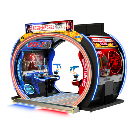
GAME DESCRIPTION GAME SUMMARY MISSION IMPOSSIBLE ARCADE is the latest rail-shooting game from one of the strongest IPs in film. One of the new features is to compete with the opposing cabinet with progress and speed. Players will “race” against unknown groups to complete each mission. -
Page 96: Lobby
Use the controller to aim at ememies. You must shoot at the enemy before the enemy shoots at you. Points are awarded when enemies are destroyed. The enemy will attack if the player does not destroy it in time. Each time a player is shot by the enemy, the players life gauge will decrease. If the player’s life is depleted, the game is over (with the option to continue). -
Page 97: How To Play
HOW TO PLAY Joining the game. If a player is to join a game during another players game, the player can insert a coin(s) and press the “START” button. If enough credits are reached, the “START” button on the opposite side of the cabinet will flash and the player can press it to join the game. -
Page 98: Game Screen
GAME SCREEN Reading the Game Screen Player 1 and Player 2 life guages, score, the number of rounds loaded in the magazine will all be displayed on the left side of the screen for Player 1 and the right hand side for player 2. Available credits and subtitles will be displayed at the bottom of the screen. -
Page 99: Game Rules
GAME RULES Time Out Every mission has a time limit. The mission fails when the time limit reaches zero. Time bonuses are added when a player passes through a checkpoint. Life System Once a the game begins, the life gauge for the player(s) will be displayed at the bottom corner of the left (player 1) and right (player 2) sides of the screen. -
Page 100: Action Sequence Controls
ACTION SEQUENCE CONTROLS As the player progresses through the game they will encounter a series of mini games called “Action Sequence Controls” Tapping Action. Some sequences will require the player to interact using the Start Button. Some sequences will require the player to rapidly tap the button complete a circle. -
Page 101: Explanation Of Test And Data Display
EXPLANATION OF TEST AND DATA DISPLAY Perform tests and data checks periodically by manipulating the TEST Button and SERVICE Button in the cabinet. Follow the instructions in this chapter to conduct checks when the game machine is first installed, when money is being collected, or when the game machine does not operate properly. -
Page 102: Switch Unit And Coin Meter
9-1 SWITCH UNIT AND COIN METER. The SWITCH UNIT and COUNTERS are housed within the COINTOWER. To access these controls you will need to open the COIN door, the switches and counters can be found directly on the rear panel. Counters Test SW Service SW... - Page 103 9-2-1 SYSTEM INFORMATION Use the SERVICE button to move the cursor to the desired item. Press the TEST button to confirm. GAME NAME MissionImpossible GAME VERSION DISK IMAGE VERSION LAUNCHER VERSION SHELL VERSION IO BOARD FIRMWARE VERSION SECURITY KEY MACHINE ID xxxx-xxxx-xxxx-xxxx RESET TO FACTORY DEFAULTS CLEAR ERROR LOG...
- Page 104 9-2-2 SYSTEM INFORMATION From the GAME TEST MENU screen - Using the SERVICE BUTTON to select INPUT TEST MODE and press the TEST BUTTON to enter The INPUT TEST allows you to check each device separately. Please check regularly. PLAYER1 CONTROLLER X PLAYER1 CONTROLLER Y PLAYER1 CONTROLLER TRIGGER L PLAYER1 CONTROLLER TRIGGER R...
- Page 105 9-2-3 OUTPUT TEST From the GAME TEST MENU screen - Using the SERVICE BUTTON to select OUTPUT TEST MODE and press the TEST BUTTON to enter The OUTPUT TEST allows you to check each device separately. Please check regularly. PLAYER1 START LAMP PLAYER2 START LAMP CABINET LIGHTING (CTR/ ATTRACT...
- Page 106 9-2-4 CALIBRATION From the GAME TEST MENU screen - Using the SERVICE BUTTON to select CALIBRATION and press the TEST BUTTON to enter The CALIBRATION TEST allows you to check and adjust the controller alignment on screen. PLAYER1 CONTROLLER X PLAYER1 CONTROLLER Y PLAYER2 CONTROLLER X PLAYER2 CONTROLLER Y...
- Page 107 9-2-5 COIN SETTINGS From the GAME TEST MENU screen - Using the SERVICE BUTTON to select COIN SETTINGS and press the TEST BUTTON to enter This test allows you to configure coins / game specifics. COIN 0000 COUNT CREDITS 0000 SERVICE 0000 CREDITS...
- Page 108 9-2-6 SOUND TEST From the GAME TEST MENU screen - Using the SERVICE BUTTON to select SOUND TEST and press the TEST BUTTON to enter The SOUND TEST allows you to check audio output from speakers and shakers. AUDIO IN ATTRACT NORMAL SPEAKER TEST LEFT...
- Page 109 9-2-7 SCREEN TEST From the GAME TEST MENU screen - Using the SERVICE BUTTON to select SCREEN TEST and press the TEST BUTTON to enter The SCREEN TEST allows you to check visial output. COLOUR BARS BRIGHTNESS ALIGNMENT BACK Use the SERVICE button to move the cursor to the desired item.
- Page 110 9-2-8 NETWORK TEST From the GAME TEST MENU screen - Using the SERVICE BUTTON to select NETWORK TEST and press the TEST BUTTON to enter The NETWORK TEST allows you to set and check the communication link between cabinets. NETWORK STATUS OK - SERVER OK - CLIENT FAILED...
- Page 111 9-2-9 BOOKKEEPING BOOKKEEPING PAGE 1/4 SUMMARY From the GAME TEST MENU screen - Using the SERVICE BUTTON to select BOOKKEEPING and press the TEST BUTTON to enter The BOOKKEEPING TEST allows you to evaluate the game performace. COIN CREDITS SERVICE CREDITS TOTAL CREDITS BOOKKEEPING LAST CLEARED 00/00/0000 - 00:00...
- Page 112 BOOKKEEPING PAGE 2/4 PLAYS NUMBER OF GAMES NUMBER OF SINGLEPLAY FIRST PLAY CONTINUE PLAY TOTAL TIME 00D 00H 00M 00S PLAY TIME 00D 00H 00M 00S AVERAGE GAME TIME 00H 00M 00S AVERAGE PLAY TIME 00H 00M 00S LONGSET PLAY TIME 00H 00M 00S SHORTEST PLAY TIME 00H 00M 00S...
- Page 113 BOOKKEEPING PAGE 3/4 GAME HISTOGRAM 0M 00S - 0M 29S 0M 30S - 0M 59S 1M 00S - 1M 29S 1M 30S - 1M 59S 2M 00S - 2M 29S 2M 30S - 2M 59S 3M 00S - 3M 29S 3M 30S - 3M 59S 4M 00S - 4M 29S 4M 30S - 4M 59S...
- Page 114 9-2-10 CLOCK SETTINGS From the GAME TEST MENU screen - Using the SERVICE BUTTON to select CLOCK SETTING and press the TEST BUTTON to enter The CLOCK SETTING allows you to set the current time/date for your location. CURRENT TIME 00:00:00 CURRENT DATE 00/00/0000...
- Page 115 3-2-11 GAME ASSIGNMENTS From the GAME TEST MENU screen - Using the SERVICE BUTTON to select GAME ASSIGNMENTS and press the TEST BUTTON to enter The GAME ASSIGNMENTS allows you to change and set various criterias and visuals to enhance gameplay. Use the SERVICE button to move the cursor to the desired item.
- Page 116 NOTICE When cabinets are linked, only MASTER(ID:1) can controle the setting of game assignments. Client cabinet side(ID2) follows the maste cabinet setting, The client side can only set LANGUAGE, CON- TROLLER REACTION and SWIPE CARD setting. Use the SERVICE button to move the cursor to the desired item. Press the TEST button to confirm. LANGUAGE Cycles language of in-game tutorials and instructions GAME DIFFICULTY...
-
Page 117: Controller Unit(S), Switches And Buttons
CONTROLLER UNIT(S), SWITCHES AND BUTTONS • When working with the product, be sure to turn the power off. Working with the power on may cause an electric shock or short circuit. • Be careful not to damage the wires. Damaged wires may cause an electric shock, short circuit or present a risk of fire. -
Page 118: Replacing The Trigger Switch
Some fixings are small. be careful not to lose any fixings. In particular the smaller fixings around the controller covers. 10-1 REPLACING THE TRIGGER SWITCH Turn OFF the power to the machine and remove the Power cable. Using a Torx Tamper proof key or driver, remove the (8) fixings from around the Right Hand outer face of the controller. - Page 119 Using a sharp knife or blade, carefully remove the protective sleeve from around the solder joint. Unsolder the ORG and BLK wires, taking note of their positionings. Protective sleeves Solder joints Replace the switch and re solder the wires onto the new switch in their correct locations. Ensure that the protective sleeves are also replaced.
-
Page 120: Replacing The Controller I/O
10-2 REPLACING THE CONTROLLER I/O In instances whereby either or both controllers malfunction a possible cause is the GUN I/O PCB mounted beneath the center controller cover.. On the rare ocassions where the GUN I/O PCB fails, please follow these instructions for removal. -
Page 121: Replacing The Up/Down Sensors
10-3 REPLACING THE UP/DOWN SENSORS Turn OFF the power to the machine and remove the Power cable. Remove the (4) Torx tamperproof fixings from both sides of the controller and lower the base cover. Torx Tamperproof (2) Base Cover Remove the (2) machine screws which retain the cover bracket. This will enable you to gain access to the VERT Controller PCB Machine Screws (2) VERT Controller PCB... -
Page 122: Video Display
VIDEO DISPLAY The LCD display screen is adjusted prior to leaving the factory. Avoid any un- necessary adjustment. ● If the adjustment method in this manual does not resolve the problem contact the customer service number in this manual or your supplier. ●... -
Page 123: Cleaning The Screen
11-2 CLEANING THE SCREEN ● Since the LCD display screen is susceptible to damage, pay careful attention to its handling. When cleaning, refrain from using water or volatile chemicals. ● Do not climb onto the control panel. This could lead to injuries, such as bump- ing your head or falling down. -
Page 124: On Screen Adjustment Method (Osd)
11-3 ON SCREEN ADJUSTMENT METHOD (OSD) • If the adjustment method in this manual does not resolve the problem contact the customer service number in this manual or your supplier. • Do not stick tape, stickers or anything else onto the screen. Any kind of adhesive may damage the surface of the screen. - Page 125 Hot Keys The OSD offers hot key functions. To access these functions the user must not open the OSD via the Main Menu. The hotkey functions offer direct access to each equivalent function. Button Direct access Up/Plus Source select, switch to next input Down/Minus Brightness Select...
- Page 126 OSD Structure...
- Page 127 Picture Menu VGA Settings Menu Setup Menu Colour Menu...
- Page 128 User Colour Menu Input Menu OSD Menu OSD Position Menu...
- Page 129 Info Menu Advance Setup Menu...
-
Page 130: Coin Handling
COIN HANDLING This product is supplied with either am electronic coin validator (particular to Europe) or a mechanical coin acceptor (particular to USA and Asia). Identify which coin acceptor is being used and consult the relevant information within this section of the manual. Handling the Coin Jam If the coin is not rejected when the REJECT button is pressed, open the coin chute door and open the selector gate. - Page 131 CLEANING THE COIN SELECTOR (MECHANICAL). Remove and clean smears by using a soft cloth dipped in water or diluted chemical detergent and then squeezed dry. Remove the CRADLE.. When removing the retaining ring (E ring) be very careful so as not to bend the rotary shaft.
- Page 132 CLEANING THE COIN SELECTOR (SR3/ Remove and clean smears by using a damp soft cloth dipped in water. DO NOT use any diluted chemical detergent or cleansing agent as this will impair the workings of the component. GATE FIG. 12-1d Open the reject gate to gain access to the rundown path.
-
Page 133: Fault Finding
12-2 FAULT FINDING Fault Finding The following information is presented for customers’ guidance in rectifying a fault but does not cover all possible causes. All acceptors with electronic faults should be returned to an approved service centre for repair. SYMPTOM INVESTIGATE POSSIBLE CAUSE Poor Contact... -
Page 134: Switch Plate - Single Cabi (Excel)
12-3 SWITCH PLATE - SINGLE CABI (EXCEL) SEGA amusement products are fitted with either an EXCEL CREDIT PCB or a VTS (Volume, Test, Service) PCB. Both these components operate coin handling in the same way. Only one of these components are fitted. -
Page 135: Coin Region & Price Of Play Settings
12-4 COIN REGION & PRICE OF PLAY SETTINGS Table 1 12-5... - Page 136 PRICE OF PLAY SETTINGS PRICE OF PLAY BONUS DIL SWITCH 1 0.10 0.10 0.50 = 6 credits 0.20 0.20 0.50 = 3 credits 0.30 0.30 1.00 = 4 credits 0.30 0.50 = 2 credits 0.30 1.00 = 3 credits 0.40 0.40 1.00 = 3 credits 0.50...
-
Page 137: Price Of Play Quick Start - Usa
12-5 PRICE OF PLAY QUICK START - USA FIG. 12-4 DIL SWITCH BANK ONE (5 way SW1) Item Price 25cent 50cent 75cent $1.00 $2.00 DIL SWITCH BANK TWO (6 way SW3) Type Table 1 12-6... -
Page 138: Lights And Lighting
LIGHTS AND LIGHTING • When working with the product, be sure to turn the power off. Working with the power on may cause an electric shock or short circuit. • You may get burned by a hot fluorescent lamp or other lamps. Pay full attention to the lamps when performing the work. -
Page 139: Led Lighting - Floor
13-1 LED LIGHTING - FLOOR The following procedure describes the replacement of the Left side Floor Lighting Please follow the same procedure when replacing the Right side. It is recommended that this work be carried out by 2 people. Remove the power from the machine and disconnect the mains input connector from the wall socket. Remove the power from the machine and disconnect the mains input connector from the wall socket. -
Page 141: Led Lighting - Step
13-2 LED LIGHTING - STEP... -
Page 142: Led Lighting - Outer Curve
13-3 LED LIGHTING - OUTER CURVE... -
Page 143: Led Lighting - Inner Curve
13-4 LED LIGHTING - INNER CURVE... -
Page 144: Led Lighting - Control Panel
13-5 LED LIGHTING - CONTROL PANEL... -
Page 145: Led Lighting - Controller
13-6 LED LIGHTING - CONTROLLER... -
Page 146: Led Lighting - Woofer
13-7 LED LIGHTING - WOOFER... -
Page 147: Led Lighting - Billboards
13-8 LED LIGHTING - BILLBOARDS... -
Page 148: Passive Infa Red (Pir)
13-9 PASSIVE INFA RED (PIR) -
Page 149: Periodic Inspection
PERIODIC INSPECTION The items listed below require periodic check and maintenance to retain the performance of this machine and to ensure safe business operation. When handling the controller, the player will be in direct contact with it. In order to always allow the player to enjoy the game, be sure to clean it regularly. - Page 150 Cleaning the Cabinet Surfaces When the cabinet surfaces are badly soiled, remove stains with a soft cloth dipped in water or diluted with a chemical detergent and squeezed dry. To avoid damaging surface finish, do not use such solvents as thinner, benzine, etc.
- Page 151 PERIODIC INSPECTION TABLE PERIOD ITEMS DESCRIPTION As appropriate CABINET SURFACE Cleaning ELECTRONIC Inspection COMPONENTS FLOOR SURFACE Cleaning MONITOR Cleaning Daily CABINET Confirm adjusters contact floor STEPS - Loose screws CONTROLLERS Cleaning / Loose Screws CASH BOX Empty Coins Weekly CONTROLLER Check Input/Output in Test ALIGNMENT CONTROLLER FEEDBACK...
-
Page 152: Troubleshooting
TROUBLESHOOTING 15-1 TROUBLESHOOTING (WHEN NO ERROR MESSAGE IS SHOWN) • In order to prevent electric shock and short circuit, be sure to turn power off before performing work. • Be careful so as not to damage wirings. Damaged wiring can cause electric shock or short circuit. - Page 153 You can also contact SEGA using the numbers listed in the front of this manual. • When working with the product, be sure to turn the power off. Working with the power on may cause an electric shock or short circuit.
- Page 154 Start button input does not Switch fault Replace switch work Lever button does not light Lamp failure Replace lamp Stays on SEGA logo and Poor condition of cabinet Refer to list of errors does not go to advertise CPU error Contact point of purchase...
-
Page 155: Pc Game Board
PC GAME BOARD • When working with the product, be sure to turn the power off. Working with the power on may cause an electric shock or short circuit. • Be careful not to damage the wires. Damaged wires may cause an electric shock, short circuit or present a risk of fire. -
Page 156: Handling Precautions
● Some parts are the ones designed and manufactured not specifically for this product. The manufacturers may discontinue, or change the specifications of, such general-purpose parts. If this is the case, SEGA cannot repair or replace a failed product whether or not a warranty period has expired. -
Page 157: Pc Game Board - Location & Removal
16-2 PC GAME BOARD - LOCATION & REMOVAL ● When returning the game board after making repairs or replacements, make sure that there are no errors in the connection of connectors. Erroneous connections can lead to electrical shock, short circuits or fires. ●... - Page 158 Prepare to carefully disconnect all the connections to the PC Game Bd. AUDIO Power Network Blue -Front Spkrs Green - Sub Woofers Pink - Bass Shakers DVI video USB3 USB2 Camera Key Chip I/O2 PCB Dev Option Carefully disconnect all connectors attached to the PC Game Bd. The DVI video cable can be disconnected by loosening the thumb screws either side of the connector.
- Page 159 Remove the (4) fixings M4x12 SKT BH PAS located at each corner of the PC Game Board. Carefully lift away the Game Bd. Reassemble and fit the ASSY Game Bd back into position by following Steps 2 to 8 in this process in reverse order.
-
Page 160: Design-Related Parts
DESIGN-RELATED PARTS This section covers all the design related artwork. For the warning display stickers, refer to Section 1. ITEM PART NUMBER DESCRIPTION NOTES MI-0091X-01UK PANEL FRONT LIT HEADER FRONT TNX MI-0093XUK STICKER LIT HEADER TNX LWR L MI-0094XUK STICKER LIT HEADER TNX LWR R MI-0095XUK PANEL LIT HEADER TNX OUTER L MI-0096XUK... - Page 161 ITEM PART NUMBER DESCRIPTION NOTES MI-0091X-02UK PANEL FRONT LIT HEADER BACK TNX MI-0502-02UK PANEL HEADER TEAM RECO MI-1051-02UK COVER WOOFER RED MI-1052-02UK STICKER STRIP INNER CURVE RED MI-1055-02UK STICKER MON MASK L RED MI-1056-02UK STICKER MON MASK R RED MI-1057-02UK STICKER MON MASK CENTRE RED MI-1473-02UK POSTER COVER BACK DOOR UPPER RED...
-
Page 162: Parts & Service Contact Information
PARTS & SERVICE CONTACT INFORMATION - SEGA TOTAL SOLUTIONS - 42 Barwell Business Park Leatherhead Road, Chessington, Surrey, KT9 2NY United Kingdom Parts/Customer Service : +44 (0) 208 391 8060 Technical Support : +44 (0) 208 391 8072 - PLAY IT AMUSEMENTS -... -
Page 163: Wire Colour Code Table
WIRE COLOUR CODE TABLE The DC power wire color for this product is different from previous SEGA titles. Working from the previous wire colors will create a high risk of fire. The color codes for the wires used in the diagrams in the following chapter are as follows. -
Page 164: Wiring Diagrams
NOISE FILTER SWITCH 2030-16-06 514-5078-5000 CFB-4003-01UK EARTH PLATE GAME BOARD DVI-D 320W 12V SMPSU MW RSP-320-12 400-320-012-01 FRONT SPEAKERS SUBWOOFERS BASS SHAKERS USB1 USB3 SEGA AMUSEMENTS INTERNATIONAL LTD 01/02/21 RA/CW MI-00003XUK MISSION IMPOSSIBLE ARCADE PART NUMBER DATE DRAWN CHECKED DESCRIPTION... - Page 165 (D-2/4) USB A 838-0043UK AUDIO L PCBA AMP 3CH AUDIO R WOOFER 838-0043UK AUDIO L PCBA AMP 3CH AUDIO R WOOFER SEGA AMUSEMENTS INTERNATIONAL LTD 01/02/21 RA/CW MI-00003XUK MISSION IMPOSSIBLE ARCADE PART NUMBER DATE DRAWN CHECKED DESCRIPTION...
- Page 166 TEST SERVICE VOL 1 VOLUME TEST SERVICE VOL 2 VOL 3 838-14548-01AUK SWITCH & VOLUME CONTROL BOARD VIDEO WALL OPTION USB A 509-0004-RE 509-0004-BL SEGA AMUSEMENTS INTERNATIONAL LTD 01/02/21 RA/CW MI-00003XUK MISSION IMPOSSIBLE ARCADE PART NUMBER DATE DRAWN CHECKED DESCRIPTION...
- Page 167 CONNECT TO PLAYER 2 CABINET USING 600-7269-0030UK. CONNECT TO VIDEO WALL (IF FITTED) 200-6065-02-AUO 600-7920-100UK 65" LED AUO P650HVN02.4 390-2012-150RGB LED FLX STRIP RGB 1500MM MI-XXXXUK - ASSY TOP BILLBOARD SEGA AMUSEMENTS INTERNATIONAL LTD 01/02/21 RA/CW MI-00003XUK MISSION IMPOSSIBLE ARCADE PART NUMBER DATE DRAWN...
Need help?
Do you have a question about the MISSION IMPOSSIBLE ARCADE and is the answer not in the manual?
Questions and answers