BodyCraft EXP Series Owner's Manual
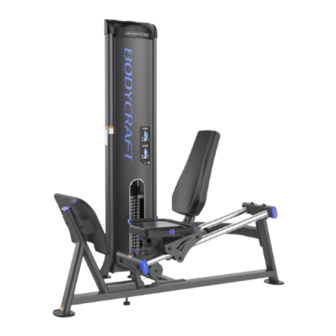
Dual leg press / calf
Hide thumbs
Also See for EXP Series:
- Owner's manual (50 pages) ,
- Assembly manual (34 pages) ,
- Operation manual (26 pages)
Table of Contents
Advertisement
Quick Links
Dual Leg Press / Calf (DLP)
Base Serial Number: _ _ _ _ _ _ _ _ _ _ _ _ _
Purchased Date: ___ / ___ / ______
Dealer's Name:__________________________
Please register your products at:
https://www.bodycraft.com/product-registration/
For the Owner's Manual
Assembly STEPS in
FULL COLOR
& additional information,
scan this QR code.
Owner's Manual
1
Open your Camera
App and point it at
the QR Code
DLP_OM v1.2
Advertisement
Table of Contents

Related Manuals for BodyCraft EXP Series


Summary of Contents for BodyCraft EXP Series
- Page 1 App and point it at the QR Code Base Serial Number: _ _ _ _ _ _ _ _ _ _ _ _ _ Purchased Date: ___ / ___ / ______ Dealer’s Name:__________________________ Please register your products at: https://www.bodycraft.com/product-registration/ Owner’s Manual DLP_OM v1.2...
- Page 2 Thank you for selecting BODYCRAFT. Your choice reflects a wise investment in you and your facility. We hope you use it for many healthy years! BODYCRAFT offers a complete array of high-quality fitness equipment. Please refer to our website www.bodycraft.com to view more ways to enhance your lifestyle.
-
Page 3: Table Of Contents
Table of Contents, Dual Leg Press / Calf (DLP) NOTE: When you have downloaded the Owner’s Manual into a PDF reader, go directly to the desired page by touching any BLUE line in this Table of Contents. Page Product Safety Information Product Safety ……………………………………………………………... -
Page 4: Product Safety
It is imperative that you retain this Assembly Instructions and be sure all warning labels are legible and intact. Replacement Assembly Instructions and labels are available from BODYCRAFT. If you are unsure about the proper use of the BODYCRAFT strength machine call your local BODYCRAFT dealer or our Customer Service Department. Contact BODYCRAFT at 800-990-5556 or support@bodycraft.com... -
Page 5: Important Notes, Recommended Tools & Cleaners
Important Notes, Recommended Tools & Cleaners, Dual Leg Press / Calf (DLP) Important Notes and Tips: Before assembly, read all instructions thoroughly and preview diagrams to help make the installation easier. 2. Make sure all parts are accounted for and in proper condition before beginning assembly. See the parts list. -
Page 6: Warning Labels, Maintenance Schedule - Details
Warning Labels, Maintenance Schedule & Serial Number, (DLP) Carefully read ALL warning, caution & maintenance schedule labels (100) (105) (108) (101) (103) (110) (107) (102) NOTE: Labels are not to scale (104) (111) -
Page 7: Warning Labels, Maintenance Schedule - Placements
Warning Labels, Maintenance Schedule & Serial Number Placement, DLP NOTE: Parts & Carefully read ALL warning, Labels are not caution & maintenance to scale schedule labels... -
Page 8: Machine Dimensions & Recommended Training Area
Machine Dimensions & Recommended Training Area, DLP... - Page 9 Assembly Parts, Dual Leg Press / Calf (DLP) 1 of 2 Part # Assembly Parts List DLP-001-ASM Frame, Weight Stack - Assembly DLP-002-ASM Frame, Main - Assembly Frame, Seat Carriage for Seat DLP-003-ASM Pad and Back Pad - Assembly DLP-004 Frame, Connector, Bottom DLP-009 Frame, Connecting, Rear...
- Page 10 Assembly Parts, Dual Leg Press / Calf (DLP) 2 of 2 NOTE: For a complete service parts list, please refer to the detailed parts list & exploded view …………………………………….at the rear of this manual. Part # Assembly Parts List DLP-030 Foot Plate, Rubber Cover DLP-031 Foot Plate...
-
Page 11: Shipping Boxes Dims & What's Inside
CWP15(5) Size: 13'' L x 6'' W x 6'' H ea. (310mm L x 130mm W x 140mm H) BODYCRAFT reserves the right to make improvements at any time which may affect color, parts, materials, size, weight, or any other aspect. -
Page 12: Product Assembly Pre-Assembly Tips
Product Assembly, Preassembly Tips, Dual Leg Press / Calf Raise (DLP) PREASSEMBLY TIP #1 – “Stage Right”. During the assembly process we will be stating Right, Left, Front, Back, Top, or Bottom. These all are in the perspective of the user in the machine facing outward with feet on the ground. See below images as examples. - Page 13 Product Assembly, Dual Leg Press / Calf (DLP) TEP 1: Install Main Frame & Weight Stack Frame w/ the Connector Frames Part # Assembly Parts & Hardware List DLP-001-ASM Frame, Weight Stack - Assembly DLP-002-ASM Frame, Main - Assembly DLP-004 Frame, Connector, Bottom DLP-009 Frame, Connecting, Rear...
- Page 14 Product Assembly, Dual Leg Press / Calf (DLP) TEP 2a: Install Rear Rail Frame to the Guide Rails TEP 2b: Install Guide Rails through the Seat Carriage Please Hand Tighten All Nuts & Bolts Until STEP 6 Part # Assembly Parts & Hardware List DLP-003-ASM Frame, Seat Carriage for Seat Pad and Back Pad - Assembly DLP-010-ASM...
- Page 15 Product Assembly, Dual Leg Press / Calf (DLP) TEP 3: Install PreAssembled Parts from STEP 2 Part # Assembly Parts List DLP-003-ASM Frame, Seat Carriage for Seat Pad and Back Pad - Assembly DLP-010-ASM Frame, Rear for Guide Rail Rods - Assembly Guide Rail for Seat Carriage , 2"...
-
Page 16: Assembly Parts & Hardware List
Product Assembly, Dual Leg Press / Calf (DLP) TEP 4: Install Foot Plate, Foot Plate Rubber Cover & Handlebar ONLY Tighten STEP 4 Frame Hardware at this time 20 ft-lbs (+/- 2 lbs) Tighten the 3/8” Nuts (for the Handlebar frame) to the recommended torque specs of 20 ft-lbs (+/- 2 lbs). -
Page 17: Step 1 - Step
Product Assembly, Dual Leg Press / Calf (DLP) TEP 5a: Install & Lube Guide Rods, Rubber Cushions, Weight Plates. & Top Plate-ASM Please Hand Tighten All Nuts & Bolts Until STEP 6 Standard 200 lb stack use the following: 1 box, 4ea of 10 lb plates = 40 lbs per CWP10(4) box Part # Assembly Parts &... - Page 18 Product Assembly, Weight Stack Stickers Installation, Dual Leg Press / Calf (DLP) TEP 5b: Clean Weight Stack IMPORTANT: Before installing the weight stack stickers, it is important to let the weight plates acclimate to room temperature. Clean Top Plate & Weight Plates front surface with: MINIMUM 65 DEGREES &...
- Page 19 Product Assembly, Dual Leg Press / Calf (DLP) TEP 6a: “Torque Time” on ALL Nuts & Bolts from STEP 1 - 5a NOTE: These recommended torque Example of being specs should be followed for correct overtightened not using the assembly and safe operation of this recommended torque specs.
- Page 20 Product Assembly, Dual Leg Press / Calf (DLP) TEP 6b: Continue“Torque Time” on ALL Frame & Guide Rod Nuts & Bolts from STEPS 1 - 5a Recommended Tools: 20 ft-lbs (+/- 2 lbs) TORQUE WRENCH w/ 9/16 SOCKET & 9/16 WRENCH Tighten all 3/8”...
- Page 21 Product Assembly, Dual Leg Press / Calf (DLP) TEP 7a - 7f: Install Main Cable, Please Hand Selector Pin w/ Lanyard, & Lower Tighten All Nuts Pulleys & Bolts Until STEP 7g The Longer Hex Head Bolt 3/8" x 4-1/2" The Shorter Hex Head Bolt 3/8"...
- Page 22 Product Assembly, Dual Leg Press / Calf (DLP) TEP 7g: “Torque Time” 5 ft-lbs (+/- 0.5 lbs) Recommended Tools: 17 ft-lbs (+/- 2 lbs) 17 ft-lbs (+/- 2 lbs) Tighten all 3/8” Bolts (for the Pulley) to the TORQUE WRENCH w/ 1/4"...
- Page 23 Product Assembly, Dual Leg Press / Calf (DLP) TEP 8: Install Weight Stack Shrouds & Cover Top Assembly 5 ft-lbs (+/- 0.5 lbs) (75) Recommended Tool: NOTE: When lowering down the Shroud Covers, confirm the back taps are behind the frame slots, locking in the Shroud Cover to the frame.
- Page 24 Product Assembly, Dual Leg Press / Calf (DLP) TEP 9: Install Seat Pads & Tighten Bolts to the Recommended Torque Specs. Part # Assembly Parts & Hardware List DLP-045 Pad, Seat DLP-046 Pad, Back DLP-066 Bolt, Hex 3/8″ x 1-1/4″ L DLP-069 Bolt, Hex 3/8″...
-
Page 25: Step 10 - Final Assembly Clean Up & Polish
Product Assembly, Final Assembly Clean up, Lube & Polish, (DLP) STEP 10a: Remove any & all Assembly Stickers, i.e. Part Numbers & Right / Left Circles ● Easy to remove with fingernail or plastic scraper ● If adhesive residue is on frame: ○... -
Page 26: Routine Schedule
Product Assembly, Routine Schedule... -
Page 27: General & Cable Inspections
Product Assembly, General & Cable Inspection... -
Page 28: Lubrication Maintenance
Product Assembly, Lubrication Maintenance... -
Page 29: Strength Cable Wear Indicators
Strength Cable Wear Indicators... -
Page 30: Detailed Parts Exploded View
Detailed Parts, Exploded View, Dual Leg Press / Calf (DLP) NOTE: Parts are not to scale... -
Page 31: Detailed Parts List
Detailed Parts List, Dual Leg Press / Calf (DLP) 1 of 5 Part # Detailed Parts List DLP-001 Frame, Weight Stack DLP-002 Frame, Main DLP-003 Frame, Seat Carriage DLP-004 Frame, Connector, Bottom DLP-005 Side Cover Bracket Plate, Right DLP-006 Side Cover Bracket Plate, Left Limit Plate for Sliding Frame, 1/4 x DLP-007 2-3/4... - Page 32 Detailed Parts List, Dual Leg Press / Calf (DLP) 2 of 5 Part # Detailed Parts List DLP-025 Foot Pad, Rubber Stopper, Rubber on Cable to Top DLP-026 Plate Clevis Bracket for Cable End DLP-027 attachment, 24mm RD × 47mm DLP-028 Pull Rod for Cable Adjustment DLP-029...
- Page 33 Detailed Parts List, Dual Leg Press / Calf (DLP) 3 of 5 Part # Detailed Parts List Plug, Square, 50mm x 50mm, DLP-053 Aluminum - BLUE w/ BC logo Plug, Rectangular, 25mm x DLP-054 50mm, Aluminum - BLUE w/ BC logo Plug, Flat Oval, PT100 x 50mm, DLP-055...
- Page 34 Detailed Parts List, Dual Leg Press / Calf (DLP) 4 of 5 Part # Detailed Parts List Bolt, Recessed Countersunk DLP-075 Head, M6 x 50mm L Screw, Inner Hex Set, DLP-076 10#-32UNF-1/8″ DLP-077 Screw, Inner Hex, M5 x 4mm L Bolt, Recessed Flat Head, 3/8"x DLP-078 1-1/4"...
- Page 35 Detailed Parts List, Dual Leg Press / Calf (DLP) Detailed Parts List, Dual Leg Ext / Curl (DEC) 4 of 4 5 of 5 Part # Detailed Parts List DLP-100 Warning Label - Fasten the machine to the floor Caution Label - The Pull-PIN must be fully DLP-101 engaged into the hole before use Warning Label - Please utilize this equipment...
-
Page 36: Required Info Before Initiating A Service Case
Service Request Required Information BEFORE Initiating a Service Case The following information is needed to help expedite troubleshooting and to ensure the correct part(s) are sent if needed for a repair: What product / model # do you have? Unit serial number? Installed by a dealer or direct sale? Date of installation? Date of service issue? -
Page 37: Product Warranty
The information you provide will never be distributed to any other individuals or agencies for any purpose. If you prefer to mail your warranty card, have the owner of the product complete the information below and return it to BODYCRAFT within 30 days from the date of equipment installation. -
Page 38: Product Warranty Registration
If the item exhibits such a defect, BODYCRAFT will, at its option, repair or replace it without cost for parts. Shipping and handling charges may apply. (BODYCRAFT may require return of the part(s) or photographic evidence of the damaged part(s) prior to replacement.) Serial number is required.
Need help?
Do you have a question about the EXP Series and is the answer not in the manual?
Questions and answers