BodyCraft EXP Series Owner's Manual
Hide thumbs
Also See for EXP Series:
- Owner's manual (45 pages) ,
- Assembly manual (34 pages) ,
- Operation manual (26 pages)
Table of Contents
Advertisement
Quick Links
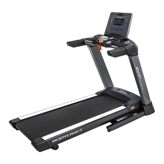
T400 Treadmill
To see in
FULL COLOR
& additional information,
Open your Camera
App and point it at
scan this QR code.
the QR Code
Base Serial Number: T402_ _ _ _ _ _ _ _ _ _ _ _
Console Serial Number: _ _ _ _ _ _ _ _ _ _ _ _ _
Purchased Date: ___ / ___ / ______
Dealer's Name:__________________________
Please register your products at:
https://www.bodycraft.com/product-registration/
Serial Number
Owner's Manual
T402 v1.6
1
Advertisement
Table of Contents

Subscribe to Our Youtube Channel
Related Manuals for BodyCraft EXP Series


Summary of Contents for BodyCraft EXP Series
- Page 1 Base Serial Number: T402_ _ _ _ _ _ _ _ _ _ _ _ Console Serial Number: _ _ _ _ _ _ _ _ _ _ _ _ _ Purchased Date: ___ / ___ / ______ Dealer’s Name:__________________________ Please register your products at: https://www.bodycraft.com/product-registration/ Serial Number Owner’s Manual T402 v1.6...
- Page 2 This page intentionally left blank...
- Page 3 Your BODYCRAFT machine has all the quality and design elements to make your workout extremely efficient and comfortable. Your new unit is a serious cardio machine that will keep you motivated, challenged and within reach of your fitness goals.
-
Page 4: Table Of Contents
Table of Contents Product Safety Information Page FCC Information …………………………………………………………………... Product Safety …………………………………………………………………….. 6 - 7 Power & Grounding Requirements Grounding Instructions …...........….……………….. Power Requirements ……………………………..…………………………….. Product Overview Product Overview Components & Tools for Assembly .……………………….. Product Specifications ……………………………………………………………. Shipping Boxes and Pre-Assembly TIP ………………………………………. -
Page 5: Fcc Information
Table of Contents Page Maintenance & Repairs Cleaning your Treadmill…............……………. Preventive Maintenance …............……………. Lubricating the Running Belt / Deck Area & Lube Icon ..….……...………… Required Info BEFORE Initiating a Service Case ………………………….. 38 - 39 Troubleshooting & Error Codes ………………………………………………... Circuit Diagram ..................... -
Page 6: Product Safety
Read, study and understand the Assembly Instructions and all the warning labels on this product. Furthermore, it is recommended to familiarize yourself and others with the proper operation and workout recommendations for this BODYCRAFT product prior to use. ● Keep children under the age of 13 and pets away from the equipment at all times. Do not allow children and pets to use or play on the equipment. - Page 7 Read, understand, and test the emergency stop procedures before use. ● To ensure proper function of your treadmill, do not install attachments or accessories not provided or recommended by BODYCRAFT. ● This T400 Treadmill is intended for home use only. DO NOT use the treadmill in any commercial, rental, or institutional setting.
-
Page 8: Grounding Instructions
Safety and Warning for a Treadmill - Grounding Instructions This product must be grounded. If the treadmill’s electrical system should malfunction or breakdown, grounding provides a path of least resistance for electric current, reducing the risk of electric shock. This product is equipped with a cord having an equipment-grounding plug. -
Page 9: Product Overview
Product Overview Components and Tools for Assembly - T400 (T402) THE FOLLOWING TOOLS ARE INCLUDED FOR ASSEMBLY: THE FOLLOWING TOOLS ARE RECOMMENDED FOR EASIER ASSEMBLY: ALLEN WRENCHES SET PHILLIPS SCREWDRIVER #2 TORQUE WRENCH 3/8 DRIVE (4mm to 10mm) w/ Magnetic TIP w/ 5mm &... -
Page 10: Product Specifications
Product Specifications - T400 (T402) RUNNING BELT: 20” W x 61” L x 2.0mm T RUNNING DECK: 1” Thick Reversible Deck HANDRAILS: 10.25” Custom Molded Soft Touch DIMENSIONS: 80” L x 35” W x 59” H WEIGHT: 260 lbs (Assembled) MAX USER WEIGHT: 350 lbs... -
Page 11: Shipping Boxes And Pre-Assembly Tip
Remove all packing materials from your area and place them back into the box. Do not dispose of the packing materials until assembly is completed. Read each step carefully before beginning. BODYCRAFT reserves the right to make improvements at any time which may affect color, parts, materials, size, weight, or any other aspect. -
Page 12: Assembly Parts & Hardware
Assembly Parts & Hardware - T400 (T402) Large Box #1 Small Box #2... -
Page 13: Product Assembly Instructions
Product Assembly NOTE: Many images shown are GENERIC for the EXP Series Treadmills T1000 / T800 / T400 on multiple assembly STEPS. STEP 1 – Upright Post-Right Wiring Connection Lay the Upright Post-Right (064) next to the treadmill’s Base Assembly (001-ASM) on its right side. - Page 14 Product Assembly Only loosely tighten ALL BOLTS until STEP 8 STEP 2 – Install Upright Post - Right Attach the Upright Post - Right (064) to the Base Assembly (001-ASM) using the following hardware: Four Allen Head Bolts, M8 x 20mm L (072) Note: See CAD image on right and both Fig 4 and Fig 5 for examples.
- Page 15 Product Assembly Product Assembly Only loosely tighten ALL BOLTS until STEP 8 STEP 3 – Install Upright Post - Left Attach the Upright Post - Left (063) to the Base Assembly (001-ASM) using the following hardware: Four Allen Head Bolts, M8 x 20mm L (072) Recommended Tool: ALLEN WRENCH...
- Page 16 Product Assembly – TEP 5 Installing the Dashboard Assembly Gently lay the Left Side of the Dashboard Assembly (077-ASM) on the running belt area. See example pic. on Fig. 6. Then connect the following cables from the Dashboard Assembly (077-ASM) - Right Side to the Upright Post - Right (064): Cable - Upper (#168 w/6pin) <<<...
- Page 17 Product Assembly Product Assembly Only loosely tighten ALL BOLTS until STEP 8 – TEP 6 Installing the Dashboard Assembly to the Upright Posts back side bolts Fig. 8 TIP: Easier to line up the front and back bolts to the holes for STEP 6a thru STEP 6b, when using an #2 Phillips Screwdriver in the side holes to push up or down for...
- Page 18 Product Assembly Product Assembly Only loosely tighten ALL BOLTS until STEP 8 – TEP 7 Preparing to Fully Tighten the Upright Posts Before fully tightening to Torque Specs in STEP 8, gently hand screw in half-way, all 4 Allen Head Bolts, M8 x 20mm on both sides of the Upright Posts to the Base Frame Assembly (001-ASM) and the Dashboard Assembly (077-ASM), See...
- Page 19 Product Assembly Product Assembly 20 ft-lbs +/- 2 lbs STEP 8 – “Torque Time” Tighten all Allen Head Bolts to the Recommended Torque Specs of 20 ft-lbs (+/- 2 lbs). These are from STEP 2 to STEP 7. See Fig. 11 as an example. 20 ft-lbs +/- 2 lbs 20 ft-lbs...
- Page 20 Product Assembly Product Assembly – TEP 9 Installing the Handlebar Covers - Right & Left Recommended Tool: Attach the Handlebar Cover - Right (142) and the Handlebar Cover - Left (141) to the Dashboard Assembly (077-ASM) using the the following hardware: ALLEN WRENCH Two Allen Head Bolts, M8 x 20mm L (072), Right Cover Two Allen Head Bolts, M8 x 20mm L (072), Left Cover...
- Page 21 Product Assembly Product Assembly – TEP 11 Installing the Upright Post Covers - Right & Left Recommended Tool: PHILLIPS SCREWDRIVERS #2 w/ Magnetic TIP Attach the Upright Post Cover - Right (140) to the Upright Post - Right (064) using the following hardware: Two Screws M5 x 12mm L (150) Then attach the Upright Post Cover - Left (139) to the...
- Page 22 Product Assembly STEP 15 – Console Wiring to the Dashboard Assembly. Connect the following cables from the Console (099) to the Dashboard Assembly (077-ASM): 1st Cable - Break-Out Board to Console - Lower (#170 w/9pin) <<<< --- >>> Cable - Main Console (#220 w/9pin) 2nd Cable - Break-Out Board to Console - Lower (#107 w/2pin) <<<<...
- Page 23 Product Assembly Product Assembly STEP 16 – Secure the Console to the Dashboard Assembly. Attach the Console (099) to the Dashboard Assembly (077-ASM) using the following hardware: Two Allen Head Bolts, M6 x 35mm L (149) Recommended Tool: ALLEN WRENCH 13 ft-lbs +/- 1 lbs b.
-
Page 24: Wall Outlet, Breaker And Extension Cords
Product Assembly STEP 17 – Power Cord Confirm the Power Cord (156) is attached to the Base Assembly (001-ASM). See CAD image to left. This should be secured from the Locking Screw-in Clip (137) to the AC Socket/Input Power (025). See Fig. 20 below using the pre-installed hardware: Screw M4 x 12mm L (006) Fig. -
Page 25: How To Setup The Treadmill Folding & Moving The Treadmill
Product Assembly Product Setup - Folding the Treadmill When you need more room in your home or simply want to move your treadmill to another location, it is very easy to do so with our exclusive Fold-N-Go Feature. Warning: Before folding the treadmill, make sure the running surface has come to a completed stop and it is at 0°... -
Page 26: Unfolding The Treadmill
Product Assembly Product Setup - Unfolding the Treadmill Step 1: With the treadmill in a folded position, firmly grab the treadmill deck with both hands at the side rail ends. Step 2: Slightly push UP on the treadmill deck and use your foot to push forward on the upper part of the locked cylinder. -
Page 27: Spacing Requirements
In some cases you may need to purchase an optional mat that will also help level all 4 contact points. Mats will also help reduce noise and can help to protect most types of flooring. If you wish to purchase a mat, contact the dealer you purchased the treadmill from or contact BODYCRAFT. -
Page 28: Running Belt Tension & Alignment
Follow these steps after the assembly STEPS to ensure proper function of your treadmill! ● If you are not comfortable performing these STEPS, please contact your local BODYCRAFT dealer or our customer support department to arrange a qualified technician to come to your home or commercial location. -
Page 30: Console Options
Console Options 16” SmartTouch Console 10” Smart Touch Console 9” LCD Console www.bodycraft.com/10TS-qr.html www.bodycraft.com/16TS-qr.html www.bodycraft.com/9LCD-qr.html... -
Page 31: Console Operating Instruction
Console Operations Instructions - T400 (T401 & T402) Please read the console operational instructions thoroughly and get familiar with the console layout. Practice using this console before you start to get a better understanding of the functions. Below are the console layout and detailed operational instructions. To power up the treadmill, locate the power cord attached to the front of the treadmill and plug it into a Dedicated 120V/15A for home use ONLY with a grounded wall outlet. -
Page 32: Heart Rate Monitoring Grips & Wireless Receiver
Heart Rate Monitoring Device & Exercise Tips Pulse Hand Grips This product comes standard with stainless steel pulse hand grips. To activate, gently grasp both hand grips to obtain a heart rate reading. The sensors that provide touch heart rate readings are reliant upon a pulse from the hands that is strong. -
Page 33: Erratic Heart Rate Readings & Exercise Tips
Heart Rate Monitoring Device Built in Wireless Heart Rate Receiver Note: Chest strap transmitter does not come with this unit; contact BODYCRAFT, or your dealer for purchase. This product is equipped with a built-in receiver for your Heart Rate monitoring. Any Heart Rate telemetry strap that transmits at 5 kHz is compatible. -
Page 34: Cleaning Your Treadmill
Cleaning your Treadmill CAUTION: Do not use any acidic cleaners. Doing so will discolor the plastics, painted surfaces and powder coatings. Never pour water or spray liquids on any part of the item. 1. Turn off and unplug the treadmill power cord from the wall before using any cleaning product. 2. -
Page 35: Preventive Maintenance
(Example of changing oil and rotating tires on new car.) To maximize the life of your treadmill, and minimize downtime, all BODYCRAFT equipment requires regular cleaning and maintenance performed on a scheduled basis. Always unplug the power cord from the wall before servicing near potential moving parts or under the hood. -
Page 36: Lubricating The Running Belt / Deck Area & Lube Icon
Preventive Maintenance page. STEP 2: Take the BODYCRAFT 100% Pure Silicone Oil Bottle and cut the tip off. Then lift the running belt up and away from the deck as far as you can on the left side of the treadmill. Point the silicone bottle nozzle towards the center of the running deck. -
Page 38: Troubleshooting & Error Codes
This troubleshooting guide is intended to assist diagnostics only and is not all inclusive. Technical specifications, error codes and programming are subject to change without notice. BODYCRAFT accepts no liability for any damage or loss suffered by persons who rely wholly or in part on any description or statement contained within this manual. - Page 39 Troubleshooting & Error Codes on DC Motor Treadmill - Basics 2 of 2 Lube icon: When the lube icon comes on, means the treadmill is due for lubrication maintenance. Please follow the owner’s manual lubrication procedure to lubricate the tread/deck. AFTER the lubrication procedure is complete: 9”...
-
Page 40: Circuit Diagram
Circuit Diagram - T400 (T401 & T402) -
Page 41: Parts Lists
Part Lists - Detailed - T400 (T401 & T402) 1 of 3 Part # Description Part # Description T402:001 Main Base Frame ( DIAMOND GRAY ) T402:047 Base Folding Frame ( DIAMOND GRAY ) T402:002 Elastomer Shock Absorbers - 1st Row - Front T402:048 Foot Cover T402:003... - Page 42 End Plug Cover - Incline Motor Tube T402:164 Wire - Switch to Filter - Red 210mm Sticker - BODYCRAFT for Side Step Rails - Left & Cable - Lower Control Board to Break-Out Board - T402:120 Right - Single Sided...
-
Page 43: Parts Exploded Views
Ground Wire Female - Dashboard - Down 600mm Handrail Arms - Quick Key Speed/Incline - Control T402:189 Sticker - EXP Series for Upright Post T402:181 Board w/ buttons Product Parts Exploded View - Drive System - T400 (T401 & T402) - Page 44 Product Parts Exploded View - Dashboard Assembly - T400 (T401 & T402) Dashboard Wiring on YouTube...
- Page 45 Product Parts Exploded View - Upright Posts Assembly - T400 (T401 & T402) Left Side Right Side...
- Page 46 Product Parts Exploded View - Base Assembly - T400 (T401 & T402)
- Page 47 Product Parts Exploded View - Base Covers & Incline Frame - T400 (T401 & T402)
-
Page 48: Product Warranty
If the item exhibits such a defect, BODYCRAFT will, at its option, repair or replace it without cost for parts. Shipping and handling charges may apply. (BODYCRAFT may require return of the part(s) or photographic evidence of the damaged part(s) prior to replacement.) Serial number is required. -
Page 49: Product Warranty Registration
Warranty Registration - Cardio Thank you for purchasing a BODYCRAFT product. To validate the product warranty the fast and easy way, please go on-line now to https://www.bodycraft.com/product-registration.html and register your product. The information you provide will never be distributed to any other individuals or agencies for any purpose. If you prefer to mail your warranty card, have the owner of the product complete the information below and return it to BODYCRAFT within 30 days from the date of equipment installation.
Need help?
Do you have a question about the EXP Series and is the answer not in the manual?
Questions and answers