BodyCraft EXP Series Owner's Manual
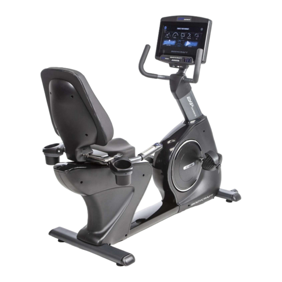
Recumbent bike
Hide thumbs
Also See for EXP Series:
- Owner's manual (50 pages) ,
- Assembly manual (34 pages) ,
- Operation manual (26 pages)
Table of Contents
Advertisement
Quick Links
R1000
Recumbent
Bike
To see in
FULL COLOR
Open your Camera
App and point it at
the QR Code
& additional information,
scan this QR code.
Base Serial Number: U _ _ _ _ _ _ _ _ _ _ _ _ _
Console Serial Number: _ _ _ _ _ _ _ _ _ _ _ _ _
Purchased Date: ___ / ___ / ______
Dealer's Name:__________________________
Serial Number
Please register your products at:
https://www.bodycraft.com/product-registration/
Owner's Manual
R1K1 v1.4
1
Advertisement
Table of Contents


Need help?
Do you have a question about the EXP Series and is the answer not in the manual?
Questions and answers