Table of Contents
Advertisement
Quick Links
Advertisement
Table of Contents
Troubleshooting

Related Manuals for Supermicro A+ Server AS -1015SV-WTNRT


Summary of Contents for Supermicro A+ Server AS -1015SV-WTNRT
- Page 1 A+ Server ® AS -1015SV-WTNRT USER’S MANUAL Revision 1.0...
- Page 2 State of California, USA. The State of California, County of Santa Clara shall be the exclusive venue for the resolution of any such disputes. Supermicro's total liability for all claims will not exceed the price paid for the hardware product.
- Page 3 If you have any questions, please contact our support team at: support@supermicro.com This manual may be periodically updated without notice. Please check the Supermicro website for possible updates to the manual revision level. Secure Data Deletion A secure data deletion tool designed to fully erase all data from storage devices can be found on our website: https://www.supermicro.com/about/policies/disclaimer.cfm?url=/wdl/utility/...
-
Page 4: Table Of Contents
Preface Contents Chapter 1 Introduction 1.1 Overview ..........................9 1.2 System Features ........................10 Front View .........................10 Drive Carrier Indicators .....................11 Control Panel .........................12 Rear View ..........................13 1.3 System Architecture ......................15 Main Components ......................15 1.4 System Block Diagram .......................16 1.5 Motherboard Layout ......................17 Quick Reference Table ......................18 Chapter 2 Server Installation 2.1 Overview ..........................19... - Page 5 Preface 3.3 Processor and Heatsink Installation ...................29 3.4 Memory Support and Installation ..................36 Memory Support ........................36 DIMM Module Population ....................37 DIMM Installation ......................38 DIMM Removal .........................38 3.5 Motherboard Battery ......................39 3.6 Storage Drives ........................40 Installing Drives .........................40 Installing M.2 Solid State Drives ..................43 To Install M.2 SSDs .......................43 3.7 System Cooling ........................44 Fans ..........................44...
- Page 6 Preface Chapter 5 Software 5.1 Microsoft Windows OS Installation ..................64 5.2 Driver Installation ........................66 5.3 SuperDoctor 5 ........................67 ® 5.4 BMC ............................68 BMC ADMIN User Password ....................68 Chapter 6 Optional Components 6.1 Storage Drive Options ......................69 6.2 Storage Control Cards .......................69 6.3 TPM Security Module ......................70 Chapter 7 Troubleshooting and Support 7.1 Information Resources .......................71...
- Page 7 Preface 7.10 Reporting an Issue ......................82 Technical Support Procedures ..................82 Returning Merchandise for Service ...................83 7.11 Feedback ..........................83 Appendix A Standardized Warning Statements for AC Systems Appendix B System Specifications...
- Page 8 San Jose, CA 95131 U.S.A. Tel: +1 (408) 503-8000 Fax: +1 (408) 503-8008 Email: marketing@supermicro.com (General Information) Sales-USA@supermicro.com (Sales Inquiries) Government_Sales-USA@supermicro.com (Gov. Sales Inquiries) support@supermicro.com (Technical Support) RMA@supermicro.com (RMA Support) Webmaster@supermicro.com (Webmaster) Website: www.supermicro.com Europe Address: Super Micro Computer B.V.
-
Page 9: Chapter 1 Introduction
1U (WxHxD) 17.2” x 1.7” x 25.6” (436.9 x 43.2 x 650.2 mm) Notes: A Quick Reference Guide can be found on the product page of the Supermicro website. The following safety models associated with the AS -1015SV-WTNRT have been certified as compliant with CSA or UL models: 815-R8H13, 815-8. -
Page 10: System Features
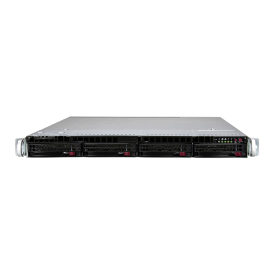
Chapter 1: Introduction 1.2 System Features The following views of the system display the main features. Refer to Appendix B for additional specifications. Front View Control Panel Service Tag with BMC Password Figure 1-1. Front View System Features: Front Item Description Service Tag Service or asset tag has the BMC password details... -
Page 11: Drive Carrier Indicators
Chapter 1: Introduction Drive Carrier Indicators Each drive carrier has two LED indicators: an activity indicator and a status indicator. For RAID configurations using a controller, the meaning of the status indicator is described in the table below. Drive Carrier LED Indicator Color Blinking Pattern Behavior for Device... -
Page 12: Control Panel
Chapter 1: Introduction Control Panel Power Unit LED Button Reset Information LED Power LED LAN2 LED Storage Drive LED LAN1 LED Figure 1-2. Control Panel Control Panel Features Feature Description Push this button to turn on the blue UID LED indicators both at the front and at the rear. UID LED Button This helps in identifying the unit when requiring service, especially when it is part of a large installation. -
Page 13: Rear View
Chapter 1: Introduction Rear View Dedicated BMC LAN Port PWS1 PWS2 VGA Port Two 10G LAN Ports Four USB 3.0 Ports COM Port Figure 1-3. System: Rear View System Features: Rear Feature Description Power Supplies Two redundant power supply modules. PWS1 on the left and PWS2 on the right. COM Port One serial port BMC LAN Port... - Page 14 Chapter 1: Introduction Power Supply Indicators Power Supply Condition Green LED Amber LED No AC Power to Power Supply Power Supply critical events causing a shutdown/ failure/ OCP/ OVP/ Fan Fail/ OTP/ UVP Power Supply Warning Events Where the power supply continues to operate;...
-
Page 15: System Architecture
Chapter 1: Introduction 1.3 System Architecture This section shows the locations of the system's main components. Main Components Power Supply Module(s) Processor DIMM Slots Heatsink System Fans Figure 1-4. System: Top View System Features: Top Feature Description Power Supply Dual 860 W Titanium high-efficiency redundant power supply modules Motherboard H13SVW-NT DIMM slots... -
Page 16: System Block Diagram
Chapter 1: Introduction 1.4 System Block Diagram 6 DDR5 DIMM Slots PCIe 3.0 x2 AMD EPYC PCIe 3.0 x2 SXB1 Riser Slot PCIe x32 PCIe x16 (CPU0) SXB2 Riser Slot (32 PCIe Lanes) (16 PCIe Lanes) JMCIO1 BCM57416 Controller Controller (PCIe x8 / AST2600 2x NVMe) -
Page 17: Motherboard Layout
Chapter 1: Introduction 1.5 Motherboard Layout Below is a layout of the H13SVW-NT motherboard with jumper, connector and LED locations shown. See the table on the following page for descriptions. For detailed descriptions, pinout information and jumper settings, refer to Chapter 4 or the Motherboard Manual. -
Page 18: Quick Reference Table
PWR supply (I2C) System Management Bus JPWR1 24-pin ATX power supply connector JPWR2 12V 8-pin ATX CPU power connector JSXB1A, JSXB1B, Slots for Supermicro riser cards JSXB1C, JSXB2 JTPM1 Trusted Platform Module (TPM)/Port 80 connector LAN1, LAN2 Back panel LAN1, LAN2 connectors M.2-C1, M.2-C2... -
Page 19: Chapter 2 Server Installation
PCBs by their edges and keep them in anti-static bags when not in use. 2.2 Unpacking the System Inspect the box in which the A+ Server AS -1015SV-WTNRT was shipped, and note if it was damaged in any way. If any equipment appears damaged, file a damage claim with the carrier who delivered it. -
Page 20: Rack Precautions
Chapter 2: Server Installation • This product is not suitable for use with visual display workplace devices according to §2 of the German Ordinance for Work with Visual Display Units. Rack Precautions • Ensure that the leveling jacks on the bottom of the rack are extended to the floor so that the full weight of the rack rests on them. -
Page 21: Airflow
Chapter 2: Server Installation Airflow Equipment should be mounted into a rack so that the amount of airflow required for safe operation is not compromised. Mechanical Loading Equipment should be mounted into a rack so that a hazardous condition does not arise due to uneven mechanical loading. -
Page 22: Installing The Rails
Chapter 2: Server Installation 2.4 Installing the Rails There are a variety of rack units on the market, which may require a slightly different assembly procedure. This rail set (MCP-290-00054-0N) fits a rack between 25.6" and 33" deep. The following is a basic guideline for installing the system into a rack with the rack mounting hardware provided. - Page 23 Chapter 2: Server Installation Installing the Outer Rails 1. Measure the distance from the front rail of the rack to the rear rail of the rack. 2. Attach a short bracket to the rear side of the right outer rail, and a long bracket to the front side of the right outer rail as shown above on the right.
- Page 24 Chapter 2: Server Installation Installing the Rail Assemblies to the Rack 1. After you have installed the short and long brackets to the outer rails, you are ready to install the whole rail assemblies (outer rails with short and long brackets attached) to the rack.
-
Page 25: Installing The Chassis Into The Rack
Chapter 2: Server Installation 2.5 Installing the Chassis into the Rack Once rails are attached to the chassis and the rack, the chassis is ready to be installed into a rack. 1. Push the inner slides, which are attached to the chassis, into the grooves of the outer slide assemblies that are installed in the rack as shown below. -
Page 26: Removing The Chassis From The Rack
Chapter 2: Server Installation Removing the Chassis from the Rack Caution! It is dangerous for a single person to off-load the heavy chassis from the rack without assistance. Be sure to have sufficient assistance supporting the chassis when removing it from the rack. -
Page 27: Chapter 3 Maintenance And Component Installation
Chapter 3: Maintenance and Component Installation Chapter 3 Maintenance and Component Installation This chapter provides instructions on installing and replacing main system components. To prevent compatibility issues, only use components that match the specifications and/or part numbers given. Installation or replacement of most components require that power first be removed from the system. -
Page 28: Accessing The System
Chapter 3: Maintenance and Component Installation 3.2 Accessing the System The chassis features a removable top cover for access to the internal components. When performing service on components inside the system, remove the system from the rack and place it on a work bench or desk. Do not service with the system extended from the rack. -
Page 29: Processor And Heatsink Installation
When installing the processor and heatsink, ensure a torque driver set to the correct force is used for each screw. • Refer to the Supermicro website for updates on CPU support. Installing the Processor and Heatsink 1. Unscrew the screws holding down Force Frame in the sequence of 3-2-1. The screws are numbered on the force frame next to each screw hole. - Page 30 Chapter 3: Maintenance and Component Installation 2. The spring-loaded force frame will raise up after the last screw securing it (#1) is removed. Gently allow it to lift up to its stopping position. 3. Lift the rail frame up by gripping the lift tabs near the front end of the rail frame. While keeping a secure grip of the rail frame, lift it to a position so you can do the next step of removing the external cap.
- Page 31 Chapter 3: Maintenance and Component Installation 4. Remove the external cap from the Rail Frame by pulling it upwards through the rail guides on the rail frame. External Cap PnP Cover Cap 5. The CPU package is shipped from the factory with the blue carrier frame pre-assembled. Grip the handle of the carrier frame/CPU package assembly from its shipping tray, and while gripping the handle, align the flanges of the carrier frame onto the rails of the rail frame so its pins will be at the bottom when the rail frame is lowered later.
- Page 32 Chapter 3: Maintenance and Component Installation Note: You can only install the CPU inside the socket in one direction with the handle at the top. Make sure that it is properly inserted into the CPU socket before closing the rail frame plate.
- Page 33 Chapter 3: Maintenance and Component Installation 9. Gently lower the force frame down onto the rail frame and hold it in place until it is seated in the Socket housing. Note that the force frame is spring loaded and has to be held in place before it is secured.
- Page 34 Chapter 3: Maintenance and Component Installation 11. After the force frame is secured and the CPU package is in place, now you must install the heatsink to the frame. Lower the heatsink down till it rests securely over the four screw holes on CPU package on the socket frame.
- Page 35 Chapter 3: Maintenance and Component Installation Uninstalling the Processor and Heatsink 1. Remove the heatsink attached to the top of the CPU package by reversing the installation procedure. 2. Clean the Thermal grease left by the heatsink on the CPU package lid to limit the risk of it contaminating the CPU package land pads or contacts in the socket housing.
-
Page 36: Memory Support And Installation
Chapter 3: Maintenance and Component Installation 3.4 Memory Support and Installation Note: Check the Supermicro website for recommended memory modules. Important: Exercise extreme care when installing or removing DIMM modules to prevent any possible damage. Memory Support The H13SVW-NT supports up to 576 GB of ECC DDR5 4800 MT/s speed, RDIMM memory in six slots. -
Page 37: Dimm Module Population
Chapter 3: Maintenance and Component Installation DIMM Module Population When populating the motherboard with DIMM modules, please keep in mind the following: • Always use DDR5 DIMM modules of the same type, size and speed. • All six memory channels should be populated with each channel having equal capacity, which should provide the best performance in most cases. -
Page 38: Dimm Installation
Chapter 3: Maintenance and Component Installation DIMM Installation 1. Insert the desired number of DIMMs into the memory slots, starting from DIMMA1 Refer to the DIMM Module Population section. 2. Push the release tabs outwards on both Receptive Point ends of the DIMM slot to unlock it. 3. -
Page 39: Motherboard Battery
Chapter 3: Maintenance and Component Installation 3.5 Motherboard Battery The motherboard uses non-volatile memory to retain system information when system power is removed. This memory is powered by a lithium battery residing on the motherboard. Replacing the Battery 1. Begin by removing power from the system. -
Page 40: Storage Drives
The system supports four hot-swap 3.5" hybrid storage drive bays. The drives are mounted in drive carriers that simplify their removal from the chassis. These carriers also help promote proper airflow. Note: Enterprise level drives are recommended for use in Supermicro servers. For compatible drives, see the H13SVW-NT motherboard page. - Page 41 Chapter 3: Maintenance and Component Installation Installing a Drive To install a drive into the chassis, first remove the drive carrier from the chassis. 1. Press the release tab to release the drive carrier from its locking position. 2. Pull the drive carrier out from the chassis as shown below: Pull out the drive carrier from the chassis Drive carrier...
- Page 42 Chapter 3: Maintenance and Component Installation 4. Slide a storage drive into the drive carrier, and secure the storage drive to the drive carrier with two screws on each side of the carrier as shown below. Secure the drive with two screws on each side of the tray. Drive Drive carrier Figure 3-8.
-
Page 43: Installing M.2 Solid State Drives
Chapter 3: Maintenance and Component Installation Installing M.2 Solid State Drives The motherboard accommodates two M.2 solid state drive (SSD). The M.2 socket supports NVMe PCIe 3.0 x4 in 2280 or 22110 form factors. The 22110 form factor is recommended because the appropriate standoff comes pre-installed on the motherboard. -
Page 44: System Cooling
Chapter 3: Maintenance and Component Installation 3.7 System Cooling Fans Six 4-cm counter-rotating fans provide the cooling for the system. Each fan unit is actually made up of two fans joined back-to-back, which rotate in opposite directions. This counter- rotating action generates exceptional airflow and works to dampen vibration levels. Make sure the chassis top cover makes a good seal so air circulates properly through the chassis. -
Page 45: Installing Or Removing Air Shroud
Chapter 3: Maintenance and Component Installation Installing or Removing Air Shroud The air shroud directs airflow to maximize cooling efficiency and comes pre-installed with the system. In the rare event that the air shroud needs to be removed or installed follow the procedure below. -
Page 46: Power
Blinking Amber: When blinking, indicates that the power supply has a warning condition and continues to operate. • Solid Amber: When illuminated, indicates that the power supply is plugged in, and is in an abnormal state. The system might need service. Please contact Supermicro technical support. -
Page 47: Power Supply Module
Chapter 3: Maintenance and Component Installation Power Supply Module Changing the SC815B Power Supply Module 1. The SC815B chassis features two redundant power supply modules. Unless you are replacing both modules, there is no need to power down and/or open the chassis. 2. -
Page 48: Pcie Expansion Cards
Chapter 3: Maintenance and Component Installation 3.9 PCIe Expansion Cards The system accepts one low-profile and two full-height full-length expansion cards, mounted on riser cards and brackets. Figure 3-14. Expansion Card Slots in the Chassis Expansion Slot Locations Item Description One PCIe 5.0 x16 full-height full-length slot for a PCIe expansion card One PCIe 5.0 x16 full-height full-length slot for a PCIe expansion card One PCIe 5.0 x16 low-profile slot for a PCIe expansion card... - Page 49 Chapter 3: Maintenance and Component Installation 5. Connect cables to the expansion card as necessary. 6. Replace the chassis cover, plug the power cords into the rear of the power supply modules and power up the system. Top Load Riser Bracket Figure 3-16.
-
Page 50: Cable Routing Diagram
Chapter 3: Maintenance and Component Installation 3.10 Cable Routing Diagram Use this section to route or reroute cables. Proper routing is important to maintain airflow through the system. 4x SATA (Default) 4x SATA(Default) Storage Cables Cable Description BPN Port MB Port CBL-MCIO- SATA 0-3 SATA/SAS# 0,1,2,3... -
Page 51: Sata/Nvme Hybrid
Chapter 3: Maintenance and Component Installation 4x SATA/NVMe Hybrid Storage Cables Cable Description BPN Port MB Port CBL-MCIO-1235M5Y NVMe 0-1 NVME#0,1 JMCIO1 CBL-MCIO-1225M5Y NVMe 2-3 NVME#2,3 JMCIO5 CBL-MCIO-1270OT4S2-85 SATA 0-3 SATA/SAS# 0,1,2,3 JMCIO4 Rear PCIe Cable PCIe x16 (Slot3) PCIe x16 (Slot1) PCIe x16 (Slot2) Cable Description... -
Page 52: Sata/Sas Via Aoc 3808/3908
Chapter 3: Maintenance and Component Installation 4x SATA/SAS via AOC 3808/3908 Storage Cables Cable Description MB/AOC Port CBL-SAST-1275A-100 SAS 0-3 SATA/SAS# 0,1,2,3 Rear PCIe Cable PCIe x16 (Slot3) PCIe x16 (Slot1) PCIe x16 (Slot2) Cable Description Riser Port MB Port RSC-W-66G5 Gold Finger (Slot 1) -
Page 53: Chapter 4 Motherboard Connections
Chapter 4: Motherboard Connections Chapter 4 Motherboard Connections This section describes the connections on the motherboard and provides pinout definitions. Note that depending on how the system is configured, not all connections are required. The LEDs on the motherboard are also described here. A motherboard layout indicating component locations may be found in Chapter 1. -
Page 54: Headers And Connectors
Chapter 4: Motherboard Connections 4.2 Headers and Connectors Onboard Fan Headers (FAN1~FAN6) There are six fan headers on the motherboard. These are 4-pin fan headers; pins 1-3 are backward compatible with traditional 3-pin fans. The onboard fan speeds are controlled by Thermal Management (via Hardware Monitoring) in the BMC. - Page 55 Port 80 connection. Use this header to enhance system performance and data security. Refer to the table below for pin definitions. Please go to the following link for more information on the TPM: http://www.supermicro.com/manuals/other/TPM.pdf. Trusted Platform Module Header Pin Definitions...
- Page 56 Chapter 4: Motherboard Connections USB Ports (USB 0~3, USB 4/5) There are a total of seven USB ports supported on the motherboard. Four are located on the back panel; USB 0/1, and USB 2/3 (both are USB 3.1 compliant). There are also three ports located on the motherboard, two are on one header, USB 4/5 (3.1).
- Page 57 Chapter 4: Motherboard Connections Overheat LED/Fan Fail (JOH1) The JOH1 header is used to connect an LED indicator to provide warnings of chassis overheating or fan failure. This LED will blink when a fan failure occurs. Refer to the table below for pin definitions.
-
Page 58: Input/Output Ports
Chapter 4: Motherboard Connections 4.3 Input/Output Ports Rear I/O Ports See the figure below for the locations and descriptions of the I/O ports on the rear of the motherboard. Figure 4-1. I/O Port Locations and Definitions Rear I/O Ports Description Description Description COM Port... - Page 59 2.6 Front Control Panel for the front panel UID LED header location on JF1. Note: UID can also be triggered via IPMI on the motherboard. For more information on IPMI, please refer to the IPMI User's Guide posted on our website at http://www.supermicro.com...
-
Page 60: Jumper Settings
Chapter 4: Motherboard Connections 4.4 Jumper Settings How Jumpers Work To modify the operation of the motherboard, jumpers can be used to choose between optional settings. Jumpers create shorts between two pins to change the function of the connector. Pin #1 is identified with a thicker border line on the printed circuit board. See the diagram below for an example of jumping pins 1 and 2. - Page 61 Chapter 4: Motherboard Connections LAN Enable/Disable (JPL1) Jumper JPL1 will enable or disable LAN1/LAN2. See below for jumper settings. The default setting is enabled. GLAN Enable Jumper Settings Pin# Definition Enabled (default) Disabled...
-
Page 62: Led Indicators
Chapter 4: Motherboard Connections 4.5 LED Indicators Onboard LAN Port LEDs The motherboard's Ethernet ports have two LED indicators. The Activity LED is green and indicates connection and activity. The Link LED may be green, orange/amber, or off to indicate the speed of the connection. Refer to the tables below for more information. Link LED, Connection Link, Speed Indicator LED Color... - Page 63 Chapter 4: Motherboard Connections UID LED Indicator (LED9) The rear LED9 is located next to the UID switch. The front UID LED is located on the front panel. When you press the UID switch, both rear LED9 and front UID LED indicators will turn on.
-
Page 64: Chapter 5 Software
1. Create a method to access the MS Windows installation ISO file. That might be a USB flash drive or media drive, or the BMC KVM console. 2. Retrieve the proper RST/RSTe driver. Go to the Supermicro web page for your motherboard and click on "Download the Latest Drivers and Utilities", select the proper driver, and copy it to a USB flash drive. - Page 65 Chapter 5: Software 4. During Windows Setup, continue to the dialog where you select the drives on which to install Windows. If the disk you want to use is not listed, click on “Load driver” link at the bottom left corner. Figure 5-2.
-
Page 66: Driver Installation
The Supermicro website contains drivers and utilities for your system at https://www. supermicro.com/wdl/driver. Some of these must be installed, such as the chipset driver. After accessing the website, go into the CDR_Images (in the parent directory of the above link) and locate the ISO file for your motherboard. Download this file to a USB flash or media drive. -
Page 67: Superdoctor ® 5
5.3 SuperDoctor ® The Supermicro SuperDoctor 5 is a program that functions in a command-line or web-based interface for Windows and Linux operating systems. The program monitors such system health information as CPU temperature, system voltages, system power consumption, fan speed, and provides alerts via email or Simple Network Management Protocol (SNMP). -
Page 68: Bmc
There are several BIOS settings that are related to BMC. For general documentation and information on BMC, visit our website at: www.supermicro.com/en/solutions/management-software/bmc-resources BMC ADMIN User Password For security, each system is assigned a unique default BMC password for the ADMIN user. -
Page 69: Chapter 6 Optional Components
Chapter 6: Optional Components Chapter 6 Optional Components This chapter describes alternate configurations and optional system components. Optional Parts Storage drive options Storage control cards TPM security module 6.1 Storage Drive Options The storage drive bays can support NVMe, SATA and SAS in any combination. To enable SAS or NVMe, additional hardware is required. -
Page 70: Tpm Security Module
The JTPM1 header is used to connect a Trusted Platform Module (TPM). A TPM is a security device that supports encryption and authentication in hard drives. It enables the motherboard to deny access if the TPM associated with the hard drive is not installed in the system. Details and installation procedures are at: http://www.supermicro.com/manuals/other/TPM.pdf • AOM-TPM-9670V... -
Page 71: Chapter 7 Troubleshooting And Support
Chapter 7: Troubleshooting and Support Chapter 7 Troubleshooting and Support 7.1 Information Resources Website A great deal of information is available on the Supermicro website, supermicro.com. Figure 7-1. Supermicro Website • Specifications for servers and other hardware are available by the Products option. •... -
Page 72: Baseboard Management Controller (Bmc)
Security Center for recent security notices Supermicro Phone and Addresses 7.2 Baseboard Management Controller (BMC) The system supports the Baseboard Management Controller (BMC). BMC is used to provide remote access, monitoring and management. There are several BIOS settings that are related to BMC. -
Page 73: Troubleshooting Procedures
Chapter 7: Troubleshooting and Support 7.3 Troubleshooting Procedures Use the following procedures to troubleshoot your system. If you have followed all of the procedures below and still need assistance, refer to the "Technical Support Procedures’ and/ or ‘Returning Merchandise for Service" section(s) in this chapter. Always disconnect the AC power cord before adding, changing or installing any non hot-swap hardware components. -
Page 74: System Boot Failure
• Memory: Make sure that the memory modules are supported. Refer to the product page on our website at www.supermicro.com. Test the modules using memtest86 or a similar utility. • Storage drives: Make sure that all drives work properly. Replace if necessary. - Page 75 Chapter 7: Troubleshooting and Support • Adequate power supply: Make sure that the power supply provides adequate power to the system. Make sure that all power connectors are connected. Refer to the Supermicro website for the minimum power requirements. •...
-
Page 76: Bios Error Beep (Post) Codes
When BIOS performs the Power On Self Test, it writes checkpoint codes to I/O port 0080h. If the computer cannot complete the boot process, a diagnostic card can be attached to the computer to read I/O port 0080h (Supermicro p/n AOC-LPC80-20). For information on AMI updates, please refer to http://www.ami.com/products/. -
Page 77: Crash Dump Using Bmc
In the event of a processor internal error (IERR) that crashes your system, you may want to provide information to support staff. You can download a crash dump of status information using BMC. The BMC manual is available at https://www.supermicro.com/en/solutions/ management-software/bmc-resources. Check BMC Error Log 1. -
Page 78: Uefi Bios Recovery
Warning: Do not upgrade the BIOS unless your system has a BIOS-related issue. Flashing the wrong BIOS can cause irreparable damage to the system. In no event shall Supermicro be liable for direct, indirect, special, incidental, or consequential damages arising from a BIOS update. - Page 79 Chapter 7: Troubleshooting and Support 2. While the system is turned off, insert the USB device that contains the new BIOS binary image (SUPER.ROM). 3. Power on the system. 4. After the system is turned on, the system will enter the BIOS Recovery menu. Select "Proceed with flash update"...
- Page 80 • If the BIOS flash recovery fails, contact our RMA Department to have the BIOS chip reprogrammed. This will require shipping the board to Supermicro for repair. Submit your RMA request at https://www.supermicro.com/support/rma Please make sure to follow all instructions when returning the motherboard.
-
Page 81: Cmos Clear
7.8 Where to Get Replacement Components If you need replacement parts for your system, to ensure the highest level of professional service and technical support, purchase exclusively from our Supermicro Authorized Distributors/System Integrators/Resellers. A list can be found at: http://www.supermicro.com. -
Page 82: Bmc Reset
Chapter 7: Troubleshooting and Support 7.9 BMC Reset The BMC can be reset using the button on the front control panel or on the chassis rear. • Reset—Press and hold the button. After six seconds, the LED blinks at 2 Hz. The BMC resets and the reset duration is approximately 250 ms. -
Page 83: Returning Merchandise For Service
During the warranty period, contact your distributor first for any product problems. 7.11 Feedback Supermicro values your feedback as we strive to improve our customer experience in all facets of our business. Please email us at techwriterteam@supermicro.com to provide feedback on... -
Page 84: Appendix A Standardized Warning Statements For Ac Systems
Supermicro's Technical Support department for assistance. Only certified technicians should attempt to install or configure components. Read this appendix in its entirety before installing or configuring components in the Supermicro chassis. These warnings may also be found on our website at http://www.supermicro.com/about/... - Page 85 Appendix A: Warning Statements Warnung WICHTIGE SICHERHEITSHINWEISE Dieses Warnsymbol bedeutet Gefahr. Sie befinden sich in einer Situation, die zu Verletzungen führen kann. Machen Sie sich vor der Arbeit mit Geräten mit den Gefahren elektrischer Schaltungen und den üblichen Verfahren zur Vorbeugung vor Unfällen vertraut. Suchen Sie mit der am Ende jeder Warnung angegebenen Anweisungsnummer nach der jeweiligen Übersetzung in den übersetzten Sicherheitshinweisen, die zusammen mit diesem Gerät ausgeliefert wurden.
- Page 86 Appendix A: Warning Statements . ٌ ا ك ً ف حالة و ٌ يك أى تتسبب ف اصابة جسذ ة ٌ هذا الزهز ع ٌ خطز !تحذ ز قبل أى تعول عىل أي هعذات،يك عىل علن بالوخاطز ال ا ٌجوة عي الذوائز ٍ...
- Page 87 Appendix A: Warning Statements Warnung Vor dem Anschließen des Systems an die Stromquelle die Installationsanweisungen lesen. ¡Advertencia! Lea las instrucciones de instalación antes de conectar el sistema a la red de alimentación. Attention Avant de brancher le système sur la source d'alimentation, consulter les directives d'installation. .יש...
- Page 88 Appendix A: Warning Statements Warnung Dieses Produkt ist darauf angewiesen, dass im Gebäude ein Kurzschluss- bzw. Überstromschutz installiert ist. Stellen Sie sicher, dass der Nennwert der Schutzvorrichtung nicht mehr als: 250 V, 20 A beträgt. ¡Advertencia! Este equipo utiliza el sistema de protección contra cortocircuitos (o sobrecorrientes) del edificio.
- Page 89 Appendix A: Warning Statements Power Disconnection Warning Warning! The system must be disconnected from all sources of power and the power cord removed from the power supply module(s) before accessing the chassis interior to install or remove system components (except for hot-swap components). 電源切断の警告...
- Page 90 Appendix A: Warning Statements אזהרה מפני ניתוק חשמלי !אזהרה יש לנתק את המערכת מכל מקורות החשמל ויש להסיר את כבל החשמלי מהספק .לפני גישה לחלק הפנימי של המארז לצורך התקנת או הסרת רכיבים يجب فصم اننظاو من جميع مصادر انطاقت وإ ز انت سهك انكهرباء من وحدة امداد انطاقت...
- Page 91 Appendix A: Warning Statements Attention Seul le personnel autorisé et le personnel de maintenance qualifié doivent être autorisés à installer, remplacer ou entretenir cet équipement.. !אזהרה .יש לאפשר רק צוות מורשה ואנשי שירות מוסמכים להתקין, להחליף או לטפל בציוד זה .ينبغي...
- Page 92 Appendix A: Warning Statements Warnung Diese Einheit ist zur Installation in Bereichen mit beschränktem Zutritt vorgesehen. Der Zutritt zu derartigen Bereichen ist nur mit einem Spezialwerkzeug, Schloss und Schlüssel oder einer sonstigen Sicherheitsvorkehrung möglich. ¡Advertencia! Esta unidad ha sido diseñada para instalación en áreas de acceso restringido. Sólo puede obtenerse acceso a una de estas áreas mediante la utilización de una herramienta especial, cerradura con llave u otro medio de seguridad.
- Page 93 Appendix A: Warning Statements Battery Handling Warning! There is the danger of explosion if the battery is replaced incorrectly. Replace the battery only with the same or equivalent type recommended by the manufacturer. Dispose of used batteries according to the manufacturer's instructions 電池の取り扱い...
- Page 94 Appendix A: Warning Statements هناك خطر من انفجار يف حالة اسحبذال البطارية بطريقة غري صحيحة فعليل اسحبذال البطارية فقط بنفس النىع أو ما يعادلها مام أوصث به الرشمة املصنعة جخلص من البطاريات املسحعملة وفقا لحعليامت الرشمة الصانعة 경고! 배터리가 올바르게 교체되지 않으면 폭발의 위험이 있습니다. 기존 배터리와 동일하거나 제 조사에서...
- Page 95 Appendix A: Warning Statements ¡Advertencia! Puede que esta unidad tenga más de una conexión para fuentes de alimentación. Para cortar por completo el suministro de energía, deben desconectarse todas las conexiones. Attention Cette unité peut avoir plus d'une connexion d'alimentation. Pour supprimer toute tension et tout courant électrique de l'unité, toutes les connexions d'alimentation doivent être débranchées.
- Page 96 Appendix A: Warning Statements Backplane Voltage Warning! Hazardous voltage or energy is present on the backplane when the system is operating. Use caution when servicing. バックプレーンの電圧 システムの稼働中は危険な電圧または電力が、 バックプレーン上にかかっています。 修理する際には注意く ださい。 警告 当系统正在进行时,背板上有很危险的电压或能量,进行维修时务必小心。 警告 當系統正在進行時,背板上有危險的電壓或能量,進行維修時務必小心。 Warnung Wenn das System in Betrieb ist, treten auf der Rückwandplatine gefährliche Spannungen oder Energien auf.
- Page 97 Appendix A: Warning Statements هناك خطز مه التيار الكهزبايئ أوالطاقة املىجىدة عىل اللىحة عندما يكىن النظام يعمل كه حذ ر ا عند خدمة هذا الجهاس 경고! 시스템이 동작 중일 때 후면판 (Backplane)에는 위험한 전압이나 에너지가 발생 합니다. 서비스 작업 시 주의하십시오. Waarschuwing Een gevaarlijke spanning of energie is aanwezig op de backplane wanneer het systeem in gebruik is.
- Page 98 Appendix A: Warning Statements תיאום חוקי החשמל הארצי !אזהרה .התקנת הציוד חייבת להיות תואמת לחוקי החשמל המקומיים והארציים تركيب املعدات الكهربائية يجب أن ميتثل للقىاويه املحلية والىطىية املتعلقة بالكهرباء 경고! 현 지역 및 국가의 전기 규정에 따라 장비를 설치해야 합니다. Waarschuwing Bij installatie van de apparatuur moet worden voldaan aan de lokale en nationale elektriciteitsvoorschriften.
- Page 99 Appendix A: Warning Statements Attention La mise au rebut ou le recyclage de ce produit sont généralement soumis à des lois et/ou directives de respect de l'environnement. Renseignez-vous auprès de l'organisme compétent. סילוק המוצר !אזהרה .סילוק סופי של מוצר זה חייב להיות בהתאם להנחיות וחוקי המדינה التخلص...
- Page 100 Appendix A: Warning Statements Warnung Gefährlich Bewegende Teile. Von den bewegenden Lüfterblätter fern halten. Die Lüfter drehen sich u. U. noch, wenn die Lüfterbaugruppe aus dem Chassis genommen wird. Halten Sie Finger, Schraubendreher und andere Gegenstände von den Öffnungen des Lüftergehäuses entfernt.
- Page 101 Verbindungskabeln, Stromkabeln und/oder Adapater, die Ihre örtlichen Sicherheitsstandards einhalten. Der Gebrauch von anderen Kabeln und Adapter können Fehlfunktionen oder Feuer verursachen. Die Richtlinien untersagen das Nutzen von UL oder CAS zertifizierten Kabeln (mit UL/CSA gekennzeichnet), an Geräten oder Produkten die nicht mit Supermicro gekennzeichnet sind.
- Page 102 .قيرح وأ لطع يف ببستي دق ىرخأ تالوحمو تالباك يأ مادختسا .ميلسلا سباقلاو لصوملا مجح لبق نم ةدمتعملا تالباكلا مادختسا تادعملاو ةيئابرهكلا ةزهجألل ةمالسلا نوناق رظحيUL وأCSA ( ةمالع لمحت يتلاوUL/CSA) لبق نم ةددحملاو ةينعملا تاجتنملا ريغ ىرخأ تادعم يأ عمSupermicro.
- Page 103 사항을 준수하여 제공되거나 지정된 연결 혹은 구매 케이블, 전원 케이블 및 AC 어댑터를 사용하십시오. 다른 케이블이나 어댑터를 사용하면 오작동이나 화재가 발생할 수 있습니다. 전기 용품 안전법은 UL 또는 CSA 인증 케이블 (코드에 UL / CSA가 표시된 케이블)을 Supermicro 가 지정한 제품 이외의 전기 장치에 사용하는 것을 금지합니다. Stroomkabel en AC-Adapter...
-
Page 104: Appendix B System Specifications
Appendix B: System Specifications Appendix B System Specifications Processors Single AMD EPYC™ 8004 Series processor in Socket SP6 with up to 64 cores; CPU TDP supports up to 225 W Note: Refer to the motherboard specifications pages on our website for updates to supported processors. Chipset System on Chip BIOS... - Page 105 Appendix B: System Specifications Operating Environment Operating Temperature: 10º to 40º C (50º to 95º F) Non-operating Temperature: -30º to 60º C (-22º to 140º F) Operating Relative Humidity: 8% to 80% (non-condensing) Non-operating Relative Humidity: 8% to 95% (non-condensing) Operating Temperature based on configurations Regulatory Compliance FCC, ICES, CE, VCCI, RCM, UKCA, NRTL, CB...
Need help?
Do you have a question about the A+ Server AS -1015SV-WTNRT and is the answer not in the manual?
Questions and answers