Table of Contents
Advertisement
Quick Links
Advertisement
Table of Contents

Related Manuals for Supermicro SuperServer 1019C-HTN2


Summary of Contents for Supermicro SuperServer 1019C-HTN2
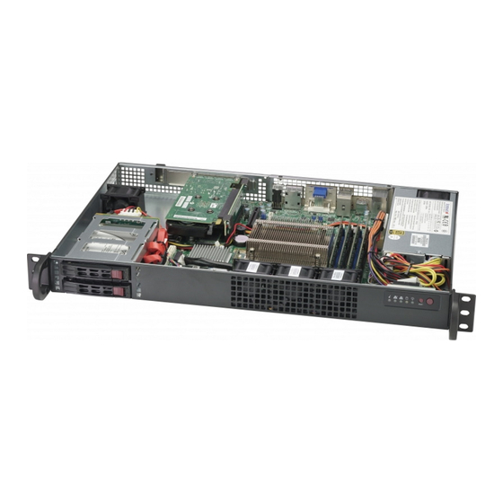
- Page 1 SuperServer ® 1019C-HTN2 USER’S MANUAL Revision 1.0...
- Page 2 State of California, USA. The State of California, County of Santa Clara shall be the exclusive venue for the resolution of any such disputes. Supermicro's total liability for all claims will not exceed the price paid for the hardware product.
- Page 3 About this Manual This manual is written for professional system integrators and PC technicians. It provides information for the installation and use of the SuperServer 1019C-HTN2. Installation and maintainance should be performed by experienced technicians only. Please refer to the 1019C-HTN2 server specifications page on our website for updates on supported memory, processors and operating systems (http://www.supermicro.com).
-
Page 4: Table Of Contents
Preface Table of Contents Chapter 1 Introduction 1.1 Overview ..........................7 1.2 Unpacking the System ......................7 1.3 System Specifications ......................8 1.4 Server Chassis Features ......................9 Control Panel ........................9 Front Features ........................10 Rear Features ........................11 1.5 Motherboard Layout ......................12 Quick Reference Table ......................13 Chapter 2 Server Installation 2.1 Overview ..........................16 2.2 Preparing for Setup ......................16... - Page 5 SuperServer 1019C-HTN2 User's Manual DIMM Module Population Sequence ................26 DIMM Installation ......................27 DIMM Removal .........................27 3.5 Chassis Components ......................28 Hard Drives ........................28 System Cooling .........................29 Installing Fans ........................29 Power Supply ........................31 Power Supply Failure ....................32 Chapter 4 Motherboard Connections 4.1 Power Connections ......................33 4.2 Headers and Connectors ....................34...
- Page 6 Super Micro Computer, Inc. 980 Rock Ave. San Jose, CA 95131 U.S.A. Tel: +1 (408) 503-8000 Fax: +1 (408) 503-8008 Email: marketing@supermicro.com (General Information) support@supermicro.com (Technical Support) Website: www.supermicro.com Europe Address: Super Micro Computer B.V. Het Sterrenbeeld 28, 5215 ML...
-
Page 7: Chapter 1 Introduction
Riser Card RSC-RR1U-E16 1.2 Unpacking the System Inspect the box the SuperServer 1019C-HTN2 was shipped in and note if it was damaged in any way. If any equipment appears damaged, please file a damage claim with the carrier who delivered it. -
Page 8: System Specifications
SuperServer 1019C-HTN2 User's Manual 1.3 System Specifications The following table provides you with an overview of the main features and specifications of the 1019C-HTN2. Please refer to Appendix C for additional specifications. System Specifications Motherboard X11SCZ-F Chassis SC510FT-203B CPU TDP support up to 80W, Intel® Xeon® E processors, 8th Gen. Intel® Core™ i3 Processors, Intel®... -
Page 9: Server Chassis Features
Chapter 1: Introduction 1.4 Server Chassis Features Control Panel The switches and LEDs located on the control panel are described below. See Chapter 4 for more details on the control panel. Figure 1-1. Control Panel View Control Panel Features Item Feature Description Information LED... -
Page 10: Front Features
SuperServer 1019C-HTN2 User's Manual Front Features The SC510FT-203B is a 11.3"-depth mini 1U chassis. See the illustration below for the features included on the front of the chassis. Figure 1-2. Chassis Front View Front Chassis Features Item Feature Description Control Panel Front control panel with LEDs and buttons (see preceding page). -
Page 11: Rear Features
Chapter 1: Introduction Rear Features The illustration below shows the features included on the rear of the chassis. Figure 1-3. Chassis Rear View Rear Chassis Features Item Feature Description Power Supply 200W 80Plus Gold Level power supply (p/n PWS-203-1H). I/O Backpanel Rear I/O ports (see Section 4.5). -
Page 12: Motherboard Layout
SuperServer 1019C-HTN2 User's Manual 1.5 Motherboard Layout Below is a layout of the X11SCZ-F with jumper, connector and LED locations shown. See the table on the following page for descriptions. For detailed descriptions, pinout information and jumper settings, refer to Chapter 4. -
Page 13: Quick Reference Table
Chapter 1: Introduction Quick Reference Table Jumper Description Default Setting JBT1 CMOS Clear Open (Normal) JPAC1 Audio Enable/Disable Pins 1-2 (Enable) JPG1 BMC Video Enable/Disable Pins 1-2 (Enable) JPL1/JPL2 LAN1/LAN2 Enable/Disable Pins 1-2 (Enable) JPME2 Manufacturing Mode Pins 1-2 (Normal) JPT1 Onboard TPM2.0 Enable/Disable Pins 1-2 (Enable) - Page 14 SuperServer 1019C-HTN2 User's Manual Connector Description JSD1 SATA Disk On Module (DOM) Power Connector JSMB1 PCH SMBus Header JTPM1 Trusted Platform Module (TPM) Header LAN1/2 Gigabit Ethernet (RJ45) Ports SLOT4, SLOT7 PCH PCI-E 3.0 x4 Slots (in x8) SLOT6 CPU PCI-E 3.0 x16 Slot...
- Page 15 Chapter 1: Introduction IMVP8-VGT PCIe3.0 x16/x8x8 PCIe x16 Slot 6 8.0GT/s SVID INTEL LGA1151 IMVP8-Vcore TDMS ASM1442K DDI 1 (Socket-H4) DVI-I PTN3355 DDR4 (CHA) DIMMA1 DIMMA2 2666MHz Digital port 3 DDI 3 Display Port++ DDR4 (CHB) DIMMB1 Digital port 2 DDI 2 Display Port++ DIMMB2...
-
Page 16: Chapter 2 Server Installation
SuperServer 1019C-HTN2 User's Manual Chapter 2 Server Installation 2.1 Overview This chapter provides advice and instructions for mounting your system in a server rack. If your system is not already fully integrated with processors, system memory etc., refer to Chapter 4 for details on installing those specific components. -
Page 17: Server Precautions
Chapter 2: Server Installation • In single rack installations, stabilizers should be attached to the rack. In multiple rack in- stallations, the racks should be coupled together. • Always make sure the rack is stable before extending a server or other component from the rack. -
Page 18: Circuit Overloading
SuperServer 1019C-HTN2 User's Manual Circuit Overloading Consideration should be given to the connection of the equipment to the power supply circuitry and the effect that any possible overloading of circuits might have on overcurrent protection and power supply wiring. Appropriate consideration of equipment nameplate ratings should be used when addressing this concern. -
Page 19: Installing The System Into A Rack
Chapter 2: Server Installation 2.3 Installing the System into a Rack The following is a basic guideline for installing the system into a rack with the rack mounting hardware provided. You should also refer to the installation instructions that came with the specific rack you are using. -
Page 20: Chapter 3 Maintenance And Component Installation
SuperServer 1019C-HTN2 User's Manual Chapter 3 Maintenance and Component Installation This chapter provides instructions on installing and replacing main system components. To prevent compatibility issues, only use components that match the specifications and/or part numbers given. Installation or replacement of most components require that power first be removed from the system. -
Page 21: Motherboard Components
CPU socket cap is in place and none of the socket pins are bent; otherwise, contact your retailer immediately. • Refer to the Supermicro website for updates on CPU support. Installing the Processor(s) Begin by removing power from the system as described in Section 3.1. -
Page 22: Installing The Lga1151 Processor
SuperServer 1019C-HTN2 User's Manual Installing the LGA1151 Processor 1. Press the load lever down to release the load plate from its locking position. Plastic Protective Cover Load Plate Load Lever 2. Gently lift the load lever to open the load plate. Remove the plastic protective cover. Do not touch the CPU socket contacts. - Page 23 Chapter 3: Maintenance and Component Installation 4. Carefully lower the CPU straight down into the socket. Do not drop the CPU on the socket, or move it horizontally or vertically to avoid damaging the CPU or socket. Inspect the four corners of the CPU to make sure that the CPU is properly installed. 5.
-
Page 24: Installing The Cpu Heatsink
SuperServer 1019C-HTN2 User's Manual Installing the CPU Heatsink Notes: • If you bought a CPU separately, use an Intel-certified multi-directional heatsink only. • Do not apply any thermal grease to the heatsink or the CPU die; the required amount has already been applied. - Page 25 Chapter 3: Maintenance and Component Installation Removing a Heatsink We do not recommend removing the heatsink. If necessary, please follow the instructions below to prevent damage to the CPU or the CPU socket. 1. Unscrew and remove the heatsink screws from the motherboard in the sequence as show in the figure below.
-
Page 26: Memory Support And Installation
SuperServer 1019C-HTN2 User's Manual OH X 3.4 Memory Support and Installation Memory Support The X11SCZ-F motherboard supports up to 64GB of DDR4 ECC/Non-ECC UDIMM with speeds of up to 2666MHz in four slots. DIMM Module Population Configuration For optimal memory performance, follow the table below when populating memory. -
Page 27: Dimm Installation
Chapter 3: Maintenance and Component Installation DIMM Installation 1. Insert DIMM modules in the following order: DIMMA2, DIMMB2, then DIMMA1, DIMMB1. For optimal performance, use memory modules of the same type and speed. 2. Push the release tabs outwards on both Notches ends of the DIMM slot to unlock it. -
Page 28: Chassis Components
SuperServer 1019C-HTN2 User's Manual 3.5 Chassis Components Hard Drives Your server may or may not have come with hard drives installed. Two hot-swap 2.5" SATA3 drives may be installed into the chassis. Follow the procedures below to install the internal drives. -
Page 29: System Cooling
Chapter 3: Maintenance and Component Installation System Cooling The SC510FT-203B includes four heavy duty fans that provide cooling for the chassis. These fans circulate air through the chassis and lower the internal temperatue within the chassis. It is very important that the chassis top cover is installed for the cooling air to circulate properly through the chassis and cool the components. - Page 30 SuperServer 1019C-HTN2 User's Manual Figure 3-6. Removing the Fan Housing 4. Disconnect the fan wiring from the connectors and carefully lift the fan housing out of the chassis. 5. To remove the fans from the fan housing, gently push upwards on the fan from the underside of the fan housing.
-
Page 31: Power Supply
100V - 240V input voltage. If the power supply unit fails, the system will shut down and you will need to replace the unit. Replacement units can be ordered directly from Supermicro. Rear Mounting Screws Power Supply... -
Page 32: Power Supply Failure
SuperServer 1019C-HTN2 User's Manual Power Supply Failure With only one power supply unit in the chassis, power must be completely removed from the server before removing and replacing the power supply unit. Removing the Power Supply If the power is on, removing power from the system as described in Section 3.1. -
Page 33: Power Connections
SuperServer 1019C-HTN2 User's Manual Chapter 4 Motherboard Connections This section describes the connections on the motherboard and provides pinout definitions. Note that depending on how the system is configured, not all connections are required. The LEDs on the motherboard are also described here. A severboard layout indicating component locations may be found in Chapter 1. -
Page 34: Headers And Connectors
Chapter 4: Motherboard Connections 4-pin 12V Power for GPU JPWR1 is a 4-pin 12V power connector for a GPU card that requires an extra 12V of power, up to 75W. Extended CMOS Battery J18 is a 2-pin connector for an external CMOS battery. Refer to Chapter 3 for battery installation instructions. - Page 35 I-SATA 3.0 Ports The X11SCZ-F has five I-SATA 3.0 ports (I-SATA0 - I-SATA4). I-SATA0 can be used with Supermicro SuperDOMs that are yellow SATA DOM connectors with power pins built in, and do not require external power cables. Supermicro SuperDOMs are backward-compatible with regular SATA HDDs or SATA DOMs that need external power cables.
- Page 36 Note: UID can also be triggered via IPMI on the motherboard. For more information on IPMI, please refer to the IPMI User's Guide posted on our website at http://www. supermicro.com/support/manuals/. UID LED Pin Definitions Color Status...
- Page 37 SuperServer 1019C-HTN2 User's Manual Front Accessible Audio Header A 10-pin audio header located at AUDIO FP allows you to use the onboard sound for audio playback. Connect an audio cable to this header to use this feature. Refer to the table below for pin definitions.
- Page 38 Chapter 4: Motherboard Connections COM Port The motherboard has two COM headers (COM1/2, COM3/4) that provide four serial connections and support RS-232 function, utilizing Supermicro PNCBL-CUSB-0984 (not included). COM Header (COM1/2, COM3/4) Pin Definitions Pin# Definition Pin# Definition DCD4 DSR4 RXD4...
- Page 39 SuperServer 1019C-HTN2 User's Manual Fan Headers There are six 4-pin fan headers on the motherboard. Although these are 4-pin fan headers, pins 1-3 are backward compatible with traditional 3-pin fans. The onboard fan speeds are controlled by Thermal Management (via Hardware Monitoring) in the BIOS. The fan speed is controlled by the BMC.
-
Page 40: Jumper Settings
Chapter 4: Motherboard Connections 4.3 Jumper Settings How Jumpers Work To modify the operation of the motherboard, jumpers can be used to choose between optional settings. Jumpers create shorts between two pins to change the function of the connector. Pin 1 is identified with a square solder pad on the printed circuit board. See the diagram below for an example of jumping pins 1 and 2. - Page 41 SuperServer 1019C-HTN2 User's Manual ME Manufacturing Mode Close JPME2 to bypass SPI flash security and force the system to use the Manufacturing Mode, which will allow the user to flash the system firmware from a host server to modify system settings. Refer to the table below for jumper settings.
- Page 42 Chapter 4: Motherboard Connections Onboard Audio Enable/Disable JPAC1 allows you to enable or disable the onboard audio support. The default position is on pins 1-2 to enable onboard audio connections. Refer to the table below for jumper settings. Audio Enable/Disable Jumper Settings Jumper Setting Definition...
-
Page 43: Led Indicators
SuperServer 1019C-HTN2 User's Manual 4.4 LED Indicators BMC Heartbeat LED BMC_HB_LED1 is the BMC heartbeat LED. When the LED is blinking green, BMC is functioning normally. BMC Heartbeat LED Indicator LED Color Definition Blinking Green BMC Normal Power LED LED1 is an Onboard Power LED. When this LED is lit, it means power is present on the motherboard. -
Page 44: Rear I/O Ports
Chapter 4: Motherboard Connections 4.5 Rear I/O Ports See the figure below for the locations and descriptions of the various I/O ports on the rear of the motherboard. Figure 4-1. I/O Port Definitions I/O Back Panel Description Description Description Description IPMI LAN LAN2 DisplayPort 1 USB10 (3.1 Gen 2) LAN1 Line Out... - Page 45 SuperServer 1019C-HTN2 User's Manual LAN Ports There are two 1GbE LAN ports (LAN1/LAN2) on the I/O back panel. The X11SCZ-F also has a dedicated IPMI LAN port on the I/O back panel. These ports accept RJ45 type cables. Refer to the table below for the pin definitions.
- Page 46 Chapter 4: Motherboard Connections Universal Serial Bus (USB) Header There are three USB 2.0 headers (USB1/2, USB3/4, USB5/6), one USB 3.1 Gen 1 header (USB7/8), one USB 3.1 Gen 2 header (USB13/14), and one USB 2.0 Type A header (USB0) on the motherboard to provide front access connection with a cable (not included).
-
Page 47: Chapter 5 Software
USB/SATA DVD drive, or a USB flash drive, or the IPMI KVM console. 2. Retrieve the proper RST/RSTe driver. Go to the Supermicro web page for your motherboard and click on "Download the Latest Drivers and Utilities", select the proper driver, and copy it to a USB flash drive. - Page 48 SuperServer 1019C-HTN2 User's Manual 4. During Windows Setup, continue to the dialog where you select the drives on which to install Windows. If the disk you want to use is not listed, click on “Load driver” link at the bottom left corner.
-
Page 49: Driver Installation
The Supermicro website contains drivers and utilities for your system at https://www. supermicro.com/wftp/driver. Some of these must be installed, such as the chipset driver. After accessing the website, go into the CDR_Images (in the parent directory of the above link) and locate the ISO file for your motherboard. Download this file to to a USB flash drive or a DVD. -
Page 50: Superdoctor ® 5
5.3 SuperDoctor ® The Supermicro SuperDoctor 5 is a program that functions in a command-line or web-based interface for Windows and Linux operating systems. The program monitors such system health information as CPU temperature, system voltages, system power consumption, fan speed, and provides alerts via email or Simple Network Management Protocol (SNMP). -
Page 51: Ipmi
The X11SCZ-F supports the Intelligent Platform Management Interface (IPMI). IPMI is used to provide remote access, monitoring and management. There are several BIOS settings that are related to IPMI. For general documentation and information on IPMI, please visit our website at: http://www.supermicro.com/products/nfo/IPMI.cfm. -
Page 52: Chapter 6 Bios
SuperServer1019C-HTN2 User's Manual Chapter 6 BIOS 6.1 Introduction This chapter describes the AMIBIOS™ Setup utility for the X11SCZ-F/-Q motherboard. The BIOS is stored on a chip and can be easily upgraded using a flash program. Note: Due to periodic changes to the BIOS, some settings may have been added or deleted and might not yet be recorded in this manual. -
Page 53: Main Setup
Note: The time is in the 24-hour format. For example, 5:30 P.M. appears as 17:30:00. The date's default value is the BIOS build date after RTC reset. Supermicro X11SCZ-F BIOS Version This feature displays the version of the BIOS ROM used in the system. - Page 54 SuperServer1019C-HTN2 User's Manual Memory Information Total Memory This feature displays the total size of memory available in the system.
-
Page 55: Advanced
Chapter 6: BIOS 6.3 Advanced Use this menu to configure advanced settings. Warning: Take caution when changing the Advanced settings. An incorrect value, a very high DRAM frequency or an incorrect BIOS timing setting may cause the system to malfunction. When this occurs, restore to default manufacturer settings. - Page 56 SuperServer1019C-HTN2 User's Manual Option ROM Messages Use this feature to set the display mode for the Option ROM. Select Keep Current to display the current AddOn ROM setting. Select Force BIOS to use the Option ROM display set by the system BIOS. The options are Force BIOS and Keep Current. Wait For "F1"...
- Page 57 Chapter 6: BIOS CPU Configuration The following CPU information will display: • Processor type • CPU Signature • Microcode Patch • Max CPU Speed • Min CPU Speed • CPU Speed • Processor Cores • Hyper Threading Technology • • SMX/TXT •...
- Page 58 SuperServer1019C-HTN2 User's Manual C6DRAM Select Enabled to activate moving the DRAM contents to PRM memory when the CPU is in the C6 state. The options are Disabled and Enabled. Hardware Prefetcher If set to Enable, the hardware prefetcher will prefetch streams of data and instructions from the main memory to the L2 cache to improve CPU performance.
- Page 59 Chapter 6: BIOS Turbo Mode Select Enable for processor cores to run faster than the frequency specified by the manufacturer. The options are Disable and Enable. Package Power Limit MSR Lock Select Enabled to lock the package power limit for the model specific registers. The options are Disabled and Enabled.
- Page 60 SuperServer1019C-HTN2 User's Manual 4-Core Ratio Limit Override This increases (multiplies) four clock speeds in the CPU core in relation to the bus speed when four CPU cores are active. Press "+" or "-" on your keyboard to change the value. The default value is 0.
- Page 61 Chapter 6: BIOS Chipset Configuration Warning: Setting the wrong values in the sections below may cause the system to malfunction. System Agent (SA) Configuration The following information will display: • SA PCIe Code Version: 7.0.53.66 • VT-d: Supported Memory Configuration Memory Configuration • Memory RC Version •...
- Page 62 SuperServer1019C-HTN2 User's Manual Memory Scrambler Use this feature to enable or disable memory scrambler support. The options are Dis- able and Enable. MRC Fast Boot Use this feature to enable or disable fast path through the memory reference code. The options are Disable and Enable.
- Page 63 Chapter 6: BIOS Aperture Size Use this feature to set the Aperture size, which is the size of system memory reserved by the BIOS for graphics device use. The options are 128MB, 256MB, 512MB, 1024MB, and 2048MB. DVMT Pre-Allocated Dynamic Video Memory Technology (DVMT) allows dynamic allocation of system memory to be used for video devices to ensure best use of available system memory based on the DVMT 5.0 platform.
- Page 64 SuperServer1019C-HTN2 User's Manual DMI Link ASPM Control Use this feature to set the ASPM (Active State Power Management) state on the SA (System Agent) side of the DMI Link. The options are Disable, L0s, L1, and L0sL1. DMI Extended Sync Control Use this feature to enable or disable the DMI extended synchronization.
- Page 65 Chapter 6: BIOS GT - Power Management Control RC6 (Render Standby) Use this feature to enable render standby support. The options are Disabled and En- abled. Maximum GT frequency Use this feature to define the Maximum GT frequency. Choose between 33MHz (RPN) and 1200Mhz (RP0).
- Page 66 SuperServer1019C-HTN2 User's Manual X2APIC Opt Out The feature "VT-D" must be enabled for this feature to be configurable. Use this feature to enable or disable X2APIC Opt Out. The options are Enable and Disable. PCH-IO Configuration PCH-IO Configuration • PCH SKU Name •...
- Page 67 Chapter 6: BIOS EDPC Use this feature to enable or disable rootport extensions for Downstream Port Contain- ment. The options are Disabled and Enabled. PCIe Speed Use this feature to select the PCI Express port speed. The options are Auto, Gen1, Gen2, and Gen3.
- Page 68 SuperServer1019C-HTN2 User's Manual Device Settings This feature displays the status of a serial port specified by the user. Change Settings This feature specifies the base I/O port address and the Interrupt Request address of a serial port specified by the user. Select Auto to allow the BIOS to automatically assign the base I/O and IRQ address.
- Page 69 Chapter 6: BIOS AST2500SEC Super IO Configuration AST2500SEC Super IO Configuration Super IO Chip AST 2500SEC Serial Port 2 Configuration Serial Port Select Enabled to enable the selected onboard serial port. The options are Disabled and Enabled. Device Settings This feature displays the status of a serial port specified by the user. Change Settings This feature specifies the base I/O port address and the Interrupt Request address of a serial port specified by the user.
- Page 70 SuperServer1019C-HTN2 User's Manual Console Redirection Settings Terminal Type This feature allows the user to select the target terminal emulation type for Console Redirection. Select VT100 to use the ASCII Character set. Select VT100+ to add color and function key support. Select ANSI to use the Extended ASCII Character Set. Select VT-UTF8 to use UTF8 encoding to map Unicode characters into one or more bytes.
- Page 71 Chapter 6: BIOS Resolution 100x31 Select Enabled for extended-terminal resolution support. The options are Disabled and Enabled. Legacy OS Redirection Resolution Use this feature to select the number of rows and columns used in Console Redirection for legacy OS support. The options are 80x24 and 80x25. Putty KeyPad This feature selects Function Keys and KeyPad settings for Putty, which is a terminal emulator designed for the Windows OS.
- Page 72 SuperServer1019C-HTN2 User's Manual SOL Data Bits Use this feature to set the data transmission size for Console Redirection. The options are 7 (Bits) and 8 (Bits). SOL Parity A parity bit can be sent along with regular data bits to detect data transmission errors. Select Even if the parity bit is set to 0, and the number of 1's in data bits is even.
- Page 73 Chapter 6: BIOS COM5 Redirection After BIOS POST Use this feature to enable or disable legacy console redirection after BIOS POST. When set to BootLoader, legacy console redirection is disabled before booting the OS. When set to Always Enable, legacy console redirection remains enabled when booting the OS. The options are Always Enable and BootLoader.
- Page 74 SuperServer1019C-HTN2 User's Manual AMT SOL Parity A parity bit can be sent along with regular data bits to detect data transmission errors. Select Even if the parity bit is set to 0, and the number of 1's in data bits is even. Select Odd if the parity bit is set to 0, and the number of 1's in data bits is odd.
- Page 75 Chapter 6: BIOS Serial Port for Out-of-Band Management/Windows Emergency Management Services (EMS) Console Redirection Select Enabled to use a COM port selected by the user for EMS Console Redirection. The options are Disabled and Enabled. *If the feature above is set to Enabled, the following features are available for configuration: Console Redirection Settings ...
- Page 76 SuperServer1019C-HTN2 User's Manual SATA And RST Configuration SATA Controller(s) This feature enables or disables the onboard SATA controller supported by the Intel PCH chip. The options are Enabled and Disabled. SATA Mode Selection Select AHCI to configure a SATA drive specified by the user as an AHCI drive. Select RAID to configure a SATA drive specified by the user as a RAID drive.
- Page 77 Chapter 6: BIOS PCH-FW Configuration ME Firmware Version: 12.0.3.1091 ME Firmware Mode: Normal Mode ME Firmware SKU: Corporate SKU ME FW Image Re-Flash Use this feature to update the Mangement Engine firmware. The options are Disabled and Enabled. Manageability Features State Enabled this feature to allow system administrators to configure the ME BIOS extension (MEBx) configuration settings.
- Page 78 SuperServer1019C-HTN2 User's Manual ASF Configuration PET Progress Use this feature to enable or disable PET Events Progress to receive PET Events alerts. The options are Disabled and Enabled. WatchDog Select Enabled to allow AMT to reset or power down the system if the operating system or BIOS hangs or crashes.
- Page 79 Chapter 6: BIOS MEBx OEM Debug Menu Enable Use this feature to enable or disable the OEM debug menu in MEBx. The options are Disabled and Enabled. Unconfigure ME Use this feature to reset the MEBx password to default. The options are Disabled and Enabled.
- Page 80 SuperServer1019C-HTN2 User's Manual Native PCIE Enable Enable this feature to grant control of PCI Express Native hot plug, PCI Express Power Management Events, and PCI Express Capability Structure Control. The options are Disabled and Enabled. Native ASPM Select Enabled for the operating system to control the ASPM, or Disabled for the BIOS to control the ASPM.
- Page 81 Chapter 6: BIOS PCI PERR/SERR Support Use this feature to enable or disable the runtime event for PCI errors. The options are Disabled and Enabled. Above 4G MMIO BIOS Assignment Select Enabled to decode a PCI device that supports 64-bit in the space above 4G Address. The options are Disabled and Enabled.
- Page 82 SuperServer1019C-HTN2 User's Manual Use this feature to select which firmware function to be loaded for LAN Port1 used for system boot. The options are Disabled and PXE. Onboard LAN2 Option ROM Use this feature to select which firmware function to be loaded for LAN Port2 used for system boot.
- Page 83 Chapter 6: BIOS Http Boot One Time Use this feature to create the HTTP boot option. The options are Disabled and Enable. Input the desrciption Highlight the feature and press enter to create a description. Boot URI Highlight the feature and press enter to create a boot URI. Trusted Computing ...
- Page 84 SuperServer1019C-HTN2 User's Manual • TPM Active Status • TPM Owner Status TXT Support Intel TXT (Trusted Execution Technology) helps protect against software-based attacks and ensures protection, confidentiality and integrity of data stored or created on the system. Use this feature to enable or disable TXT Support. The options are Disabled and Enabled. *The features in the Trusted Computing section on this page and the next are displayed if a TPM 2.0 module is detected: TPM20 Device Found...
- Page 85 Chapter 6: BIOS Platform Hierarchy Use this feature to disable or enable platform hierarchy for platform protection. The options are Disabled and Enabled. Storage Hierarchy Use this feature to disable or enable storage hierarchy for cryptographic protection. The options are Disabled and Enabled. Endorsement Hierarchy Use this feature to disable or enable endorsement hierarchy for privacy control.
-
Page 86: Event Logs
SuperServer1019C-HTN2 User's Manual 6.4 Event Logs Use this menu to configure event log settings. Change SMBIOS Event Log Settings Enabling/Disabling Options SMBIOS Event Log Change this feature to enable or disable all features of the SMBIOS Event Logging during system boot. The options are Disabled and Enabled. Erasing Settings Erase Event Log Select Enabled to erase all error events in the SMBIOS (System Management BIOS) log... - Page 87 Chapter 6: BIOS SMBIOS Event Log Standard Settings Log System Boot Event Select Enabled to log system boot events. The options are Enabled and Disabled. MECI (Multiple Event Count Increment) Enter the increment value for the multiple event counter. Enter a number between 1 to 255. The default setting is 1.
-
Page 88: Ipmi
SuperServer1019C-HTN2 User's Manual 6.5 IPMI Use this menu to configure Intelligent Platform Management Interface (IPMI) settings. BMC Firmware Revision This feature indicates the IPMI firmware revision in your system. IPMI STATUS This feature indicates the status of the IPMI firmware installed in your system. System Event Log Enabling/Disabling Options SEL Components... - Page 89 Chapter 6: BIOS When SEL is Full This feature allows the user to determine what the BIOS should do when the system event log is full. Select Erase Immediately to erase all events in the log when the system event log is full.
- Page 90 SuperServer1019C-HTN2 User's Manual Station MAC Address This feature displays the Station MAC address for this computer. Mac addresses are 6 two-digit hexadecimal numbers. Gateway IP Address This feature displays the Gateway IP address for this computer. This should be in decimal and in dotted quad form (i.e., 192.168.10.253).
- Page 91 The Disable option is for applications that require faster power on time wthout using Supermicro Update Manager (SUM) or extended IPMI features. The BMC network configuration in the BIOS setup is also invalid when IPMI Function Support is disabled. The general BMC function and motherboard health monitor such as fan control are still functioning even when this option is disabled.
-
Page 92: Security
SuperServer1019C-HTN2 User's Manual 6.6 Security Use this menu to configure the security settings for the system. Administrator Password Use this feature to set the administrator password which is required to enter the BIOS setup utility. The length of the password should be from 3 characters to 20 characters long. Password Check Select Setup for the system to check for a password at Setup. - Page 93 Chapter 6: BIOS Secure Boot Mode This feature allows the user to select the desired secure boot mode for the system. The options are Standard and Customized. *If Secure Boot Mode is set to Customized, Key Management features are available for configuration: CSM Support This feature is for manufacturing debugging purposes.
- Page 94 SuperServer1019C-HTN2 User's Manual Secure Boot variable Platform Key (PK) This feature allows the user to configure the settings of the platform keys. Details Select this feature to view the details of the Platform Key. Export Select Yes to export a PK from a file on an external media. Update Select Yes to load a factory default PK or No to load from a file on an external media.
- Page 95 Chapter 6: BIOS Append Select Yes to add the db from the manufacturer's defaults list to the existing db. Select No to load the db from a file. The options are Yes and No. Delete Select Ok to remove the db and then the system will reset to Setup/Audit Mode. ...
- Page 96 SuperServer1019C-HTN2 User's Manual OsRecovery Signatures Details Select this feature to view the details of the dbr. Export Select Yes to export a dbr from a file on an external media. Update Select Yes to load a factory default dbr or No to load from a file on an external media. Append Select Yes to add the dbr from the manufacturer's defaults list to the existing dbr.
-
Page 97: Boot
Chapter 6: BIOS 6.7 Boot Use this menu to configure boot settings. Setup Prompt Timeout Use this feature to specify the length of time (the number of seconds) for the BIOS to wait before rebooting the system when the setup activation key is pressed. Enter the value of 65535 (0xFFFF) for the BIOS to wait indefinitely. - Page 98 SuperServer1019C-HTN2 User's Manual • LEGACY/UEFI/DUAL Boot Order #7 • LEGACY/UEFI/DUAL Boot Order #8 • LEGACY/UEFI/DUAL Boot Order #9 • LEGACY/UEFI/DUAL Boot Order #10 • LEGACY/UEFI/DUAL Boot Order #11 • LEGACY/UEFI/DUAL Boot Order #12 • LEGACY/UEFI/DUAL Boot Order #13 • LEGACY/UEFI/DUAL Boot Order #14 •...
-
Page 99: Save & Exit
Chapter 6: BIOS 6.8 Save & Exit Use this menu to configure save and exit settings. Save Options Discard Changes and Exit Select this option to quit the BIOS Setup without making any permanent changes to the system configuration and reboot the computer. Select Discard Changes and Exit from the Exit menu and press <Enter>. - Page 100 SuperServer1019C-HTN2 User's Manual Default Options Restore Defaults To set this feature, select Restore Optimized Defaults and press <Enter>. These are factory settings designed for maximum system performance but not for maximum stability. Save as User Defaults To set this feature, select Save as User Defaults from the Exit menu and press <Enter>. This enables the user to save any changes to the BIOS setup for future use.
-
Page 101: Appendix A Bios Error Codes
SuperServer 1019C-HTN2 User's Manual Appendix A BIOS Error Codes A.1 BIOS Error POST (Beep) Codes During the POST (Power-On Self-Test) routines, which are performed each time the system is powered on, errors may occur. Non-fatal errors are those which, in most cases, allow the system to continue the boot-up process. - Page 102 When BIOS performs the Power On Self Test, it writes checkpoint codes to I/O port 0080h. If the computer cannot complete the boot process, a diagnostic card can be attached to the computer to read I/O port 0080h (Supermicro p/n AOC-LPC80-20). For information on AMI updates, please refer to http://www.ami.com/products/.
-
Page 103: Appendix B Standardized Warning Statements For Ac Systems
Supermicro's Technical Support department for assistance. Only certified technicians should attempt to install or configure components. Read this appendix in its entirety before installing or configuring components in the Supermicro chassis. These warnings may also be found on our website at http://www.supermicro.com/about/... - Page 104 Appendix B: Standardized Warning Statements Warnung WICHTIGE SICHERHEITSHINWEISE Dieses Warnsymbol bedeutet Gefahr. Sie befinden sich in einer Situation, die zu Verletzungen führen kann. Machen Sie sich vor der Arbeit mit Geräten mit den Gefahren elektrischer Schaltungen und den üblichen Verfahren zur Vorbeugung vor Unfällen vertraut. Suchen Sie mit der am Ende jeder Warnung angegebenen Anweisungsnummer nach der jeweiligen Übersetzung in den übersetzten Sicherheitshinweisen, die zusammen mit diesem Gerät ausgeliefert wurden.
- Page 105 SuperServer 1019C-HTN2 User's Manual . ٌ ا ك ً ف حالة و ٌ يك أى تتسبب ف اصابة جسذ ة ٌ هذا الزهز ع ٌ خطز !تحذ ز قبل أى تعول عىل أي هعذات،يك عىل علن بالوخاطز ال ا ٌجوة عي الذوائز...
- Page 106 Appendix B: Standardized Warning Statements Warnung Vor dem Anschließen des Systems an die Stromquelle die Installationsanweisungen lesen. ¡Advertencia! Lea las instrucciones de instalación antes de conectar el sistema a la red de alimentación. Attention Avant de brancher le système sur la source d'alimentation, consulter les directives d'installation. .יש...
- Page 107 SuperServer 1019C-HTN2 User's Manual Warnung Dieses Produkt ist darauf angewiesen, dass im Gebäude ein Kurzschluss- bzw. Überstromschutz installiert ist. Stellen Sie sicher, dass der Nennwert der Schutzvorrichtung nicht mehr als: 250 V, 20 A beträgt. ¡Advertencia! Este equipo utiliza el sistema de protección contra cortocircuitos (o sobrecorrientes) del edificio.
- Page 108 Appendix B: Standardized Warning Statements Power Disconnection Warning Warning! The system must be disconnected from all sources of power and the power cord removed from the power supply module(s) before accessing the chassis interior to install or remove system components. 電源切断の警告...
- Page 109 SuperServer 1019C-HTN2 User's Manual يجب فصم اننظاو من جميع مصادر انطاقت وإ ز انت سهك انكهرباء من وحدة امداد انطاقت قبم انىصىل إىن امنناطق انداخهيت نههيكم نتثبيج أو إ ز انت مكىناث الجهاز 경고! 시스템에 부품들을 장착하거나 제거하기 위해서는 섀시 내부에 접근하기 전에 반드시 전원...
- Page 110 Appendix B: Standardized Warning Statements Attention Il est vivement recommandé de confier l'installation, le remplacement et la maintenance de ces équipements à des personnels qualifiés et expérimentés. !אזהרה .צוות מוסמך בלבד רשאי להתקין, להחליף את הציוד או לתת שירות עבור הציוד واملدربيه...
- Page 111 SuperServer 1019C-HTN2 User's Manual Warnung Diese Einheit ist zur Installation in Bereichen mit beschränktem Zutritt vorgesehen. Der Zutritt zu derartigen Bereichen ist nur mit einem Spezialwerkzeug, Schloss und Schlüssel oder einer sonstigen Sicherheitsvorkehrung möglich. ¡Advertencia! Esta unidad ha sido diseñada para instalación en áreas de acceso restringido. Sólo puede obtenerse acceso a una de estas áreas mediante la utilización de una herramienta especial,...
- Page 112 Appendix B: Standardized Warning Statements Battery Handling Warning! There is the danger of explosion if the battery is replaced incorrectly. Replace the battery only with the same or equivalent type recommended by the manufacturer. Dispose of used batteries according to the manufacturer's instructions 電池の取り扱い...
- Page 113 SuperServer 1019C-HTN2 User's Manual هناك خطر من انفجار يف حالة اسحبذال البطارية بطريقة غري صحيحة فعليل اسحبذال البطارية فقط بنفس النىع أو ما يعادلها مام أوصث به الرشمة املصنعة جخلص من البطاريات املسحعملة وفقا لحعليامت الرشمة الصانعة 경고! 배터리가 올바르게 교체되지 않으면 폭발의 위험이 있습니다. 기존 배터리와 동일하거나 제...
- Page 114 Appendix B: Standardized Warning Statements ¡Advertencia! Puede que esta unidad tenga más de una conexión para fuentes de alimentación. Para cortar por completo el suministro de energía, deben desconectarse todas las conexiones. Attention Cette unité peut avoir plus d'une connexion d'alimentation. Pour supprimer toute tension et tout courant électrique de l'unité, toutes les connexions d'alimentation doivent être débranchées.
- Page 115 SuperServer 1019C-HTN2 User's Manual Backplane Voltage Warning! Hazardous voltage or energy is present on the backplane when the system is operating. Use caution when servicing. バックプレーンの電圧 システムの稼働中は危険な電圧または電力が、 バックプレーン上にかかっています。 修理する際には注意く ださい。 警告 当系统正在进行时,背板上有很危险的电压或能量,进行维修时务必小心。 警告 當系統正在進行時,背板上有危險的電壓或能量,進行維修時務必小心。 Warnung Wenn das System in Betrieb ist, treten auf der Rückwandplatine gefährliche Spannungen oder Energien auf.
- Page 116 Appendix B: Standardized Warning Statements هناك خطز مه التيار الكهزبايئ أوالطاقة املىجىدة عىل اللىحة عندما يكىن النظام يعمل كه حذ ر ا عند خدمة هذا الجهاس 경고! 시스템이 동작 중일 때 후면판 (Backplane)에는 위험한 전압이나 에너지가 발생 합니다. 서비스 작업 시 주의하십시오. Waarschuwing Een gevaarlijke spanning of energie is aanwezig op de backplane wanneer het systeem in gebruik is.
- Page 117 SuperServer 1019C-HTN2 User's Manual תיאום חוקי החשמל הארצי !אזהרה .התקנת הציוד חייבת להיות תואמת לחוקי החשמל המקומיים והארציים تركيب املعدات الكهربائية يجب أن ميتثل للقىاويه املحلية والىطىية املتعلقة بالكهرباء 경고! 현 지역 및 국가의 전기 규정에 따라 장비를 설치해야 합니다.
- Page 118 Appendix B: Standardized Warning Statements Attention La mise au rebut ou le recyclage de ce produit sont généralement soumis à des lois et/ou directives de respect de l'environnement. Renseignez-vous auprès de l'organisme compétent. סילוק המוצר !אזהרה .סילוק סופי של מוצר זה חייב להיות בהתאם להנחיות וחוקי המדינה التخلص...
- Page 119 SuperServer 1019C-HTN2 User's Manual Warnung Gefährlich Bewegende Teile. Von den bewegenden Lüfterblätter fern halten. Die Lüfter drehen sich u. U. noch, wenn die Lüfterbaugruppe aus dem Chassis genommen wird. Halten Sie Finger, Schraubendreher und andere Gegenstände von den Öffnungen des Lüftergehäuses entfernt.
- Page 120 Verbindungskabeln, Stromkabeln und/oder Adapater, die Ihre örtlichen Sicherheitsstandards einhalten. Der Gebrauch von anderen Kabeln und Adapter können Fehlfunktionen oder Feuer verursachen. Die Richtlinien untersagen das Nutzen von UL oder CAS zertifizierten Kabeln (mit UL/CSA gekennzeichnet), an Geräten oder Produkten die nicht mit Supermicro gekennzeichnet sind.
- Page 121 حجم املوصل والقابس السليم. استخدام أي كابالت ومحوالت أخرى قد يتسبب يف عطل أو حريق. يحظر قانون السالمة لألجهزة الكهربائية واملعدات استخدام الكابالت املعتمدة من قبلUL أوCSA ( والتي تحمل عالمةUL/CSA) مع أي معدات أخرى غري املنتجات املعنية واملحددة من قبلSupermicro.
- Page 122 사항을 준수하여 제공되거나 지정된 연결 혹은 구매 케이블, 전원 케이블 및 AC 어댑터를 사용하십시오. 다른 케이블이나 어댑터를 사용하면 오작동이나 화재가 발생할 수 있습니다. 전기 용품 안전법은 UL 또는 CSA 인증 케이블 (코드에 UL / CSA가 표시된 케이블)을 Supermicro 가 지정한 제품 이외의 전기 장치에 사용하는 것을 금지합니다. Stroomkabel en AC-Adapter...
-
Page 123: Appendix C System Specifications
Appendix C: System Specifications Appendix C System Specifications Processors Single IIntel® Xeon® E processors,8th Gen. Intel® Core™ i3 Processors,Intel® Celeron®, Intel® Pentium® in LGA 1151 type socket Note: Please refer to the motherboard specifications pages on our website for updates to supported processors. Chipset Intel Intel®... - Page 124 SuperServer 1019C-HTN2 User's Manual Regulatory Compliance Electromagnetic Emissions: FCC Class A, EN 55032 Class A, EN 61000-3-2/3-3, CISPR 32 Class A Electromagnetic Immunity: EN 55024/CISPR 24, (EN 61000-4-2, EN 61000-4-3, EN 61000-4-4, EN 61000-4-5, EN 61000-4-6, EN 61000-4-8, EN 61000-4-11)
Need help?
Do you have a question about the SuperServer 1019C-HTN2 and is the answer not in the manual?
Questions and answers