Table of Contents
Advertisement
Quick Links
Advertisement
Table of Contents

Related Manuals for Supermicro SuperServer 1019C-FHTN8


Summary of Contents for Supermicro SuperServer 1019C-FHTN8
- Page 1 SuperServer 1019C-FHTN8 USER’S MANUAL Revision 1.0...
- Page 2 State of California, USA. The State of California, County of Santa Clara shall be the exclusive venue for the resolution of any such disputes. Supermicro's total liability for all claims will not exceed the price paid for the hardware product.
- Page 3 If you have any questions, please contact our support team at: support@supermicro.com This manual may be periodically updated without notice. Please check the Supermicro website for possible updates to the manual revision level. Warnings Special attention should be given to the following symbols used in this manual.
-
Page 4: Table Of Contents
SuperServer 1019C-FHTN8 User's Manual Contents Chapter 1 Introduction 1.1 Overview ..........................8 1.2 Unpacking the System ......................8 1.3 System Features ........................9 1.4 Chassis Features .......................10 Control Panel ........................10 Front Features ........................11 Chassis Rear ........................12 1.5 Motherboard Layout ......................13 Quick Reference .......................14 System Block Diagram ......................15... - Page 5 Contents Chapter 3 Maintenance and Component Installation 3.1 Removing Power ........................24 3.2 Accessing the System ......................25 3.3 Motherboard Components ....................26 Processor and Heatsink Installation ..................26 Installing the LGA 1151 Processor ................26 Installing the CPU Heatsink ..................29 Memory ..........................31 Memory Support ......................31 General Guidelines for Optimizing Memory Performance ..........31 DIMM Installation ......................33 Motherboard Battery ......................34...
- Page 6 SuperServer 1019C-FHTN8 User's Manual Chapter 5 Software 5.1 Microsoft Windows OS Installation ..................56 5.2 Driver Installation ........................58 5.3 SuperDoctor 5 ........................59 ® 5.4 IPMI ............................60 Chapter 6 BIOS 6.1 Introduction .........................61 Starting BIOS Setup Utility ....................61 6.2 Main Setup .........................61 6.3 Advanced Setup Configurations ..................63...
- Page 7 Super Micro Computer, Inc. 980 Rock Ave. San Jose, CA 95131 U.S.A. Tel: +1 (408) 503-8000 Fax: +1 (408) 503-8008 Email: marketing@supermicro.com (General Information) support@supermicro.com (Technical Support) Website: www.supermicro.com Europe Address: Super Micro Computer B.V. Het Sterrenbeeld 28, 5215 ML...
-
Page 8: Overview
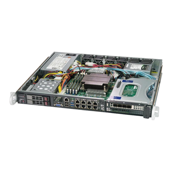
SuperServer 1019C-FHTN8 User's Manual Chapter 1 Introduction 1.1 Overview This chapter provides a brief outline of the functions and features of the 1019C-FHTN8 server. It is based on the X11SCM-LN8F motherboard and the SC513BTQC-350B chassis. In addition to the motherboard and chassis, several important parts that are included with the system are listed below. -
Page 9: System Features
Chapter 1: Introduction 1.3 System Features The following table is an overview of the main features of the 1019C-FHTN8 server. System Features Motherboard X11SCM-LN8F Chassis SC513BTQC-350B Intel Xeon E-2100, 8th Generation Core i3, Pentium, and Celeron series (in Socket H4 - LGA 1151). Memory Up to 128 GB unbuffered DIMM (UDIMM), ECC DDR4 up to 2666 MHz modules in four slots Chipset... -
Page 10: Chassis Features
SuperServer 1019C-FHTN8 User's Manual 1.4 Chassis Features Control Panel Power switches and status LEDs are located on the control panel on the front of the chassis. Figure 1-1. Control Panel Control Panel Features Item Features Description Information LED Alerts operator to several states, as noted in the table below... -
Page 11: Front Features
Chapter 1: Introduction Front Features The illustration below shows the features included on the front of the chassis. Figure 1-2. Chassis Front View Front Chassis Features Item Feature Description Control Panel Front control panel with LEDs and buttons (see preceding page) Drives Two hot-swap 2.5"... -
Page 12: Chassis Rear
SuperServer 1019C-FHTN8 User's Manual Chassis Rear The illustration below shows the features included on the rear of the chassis. Power Input Figure 1-4. Rear View... -
Page 13: Motherboard Layout
Chapter 1: Introduction 1.5 Motherboard Layout Below is a layout of the X11SCM-LN8F motherboard with jumper, connector and LED locations shown. See the table on the following page for descriptions. For detailed descriptions, pinout information and jumper settings, refer to Chapter 4. USB4/5 (3.0) JUIDB1 LAN3/7... -
Page 14: Quick Reference
SuperServer 1019C-FHTN8 User's Manual Quick Reference Jumper Description Default Setting JBT1 CMOS Clear Open (Normal) JPG1 VGA Enable Pins 1-2 (Enabled) – GLAN Enable Pins 1-2 (Enabled) JPL1 JPL8 JPME2 ME Manufacturing Mode Pins 1-2 (Normal) JWD1 Watchdog Timer Pins 1-2 (Reset) -
Page 15: System Block Diagram
Chapter 1: Introduction Description State: Status BMC_HB_LED BMC Heartbeat LED Blinking Green: BMC Normal LED4 Unit Identifier (UID) LED Solid Blue: Unit Identified LED_PWR_SB Standby Power LED Solid Green: Power Supply On PWR_LED Onboard Power LED Solid Green: System On System Block Diagram SVID IMVP8 VR... -
Page 16: Where To Get Replacement Components
For faster service, RMA authorizations may be requested online (http://www.supermicro.com/ support/rma/). Whenever possible, repack the chassis in the original Supermicro carton, using the original packaging material. If these are no longer available, be sure to pack the chassis securely, using packaging material to surround the chassis so that it does not shift within the carton and become damaged during shipping. -
Page 17: Chapter 2 Server Installation
Chapter 2: Server Installation Chapter 2 Server Installation 2.1 Overview This chapter provides advice and instructions for mounting your system in a server rack. If your system is not already fully integrated with processors, system memory etc., refer to Chapter 3 for details on installing those specific components. Caution: Electrostatic Discharge (ESD) can damage electronic components. -
Page 18: Server Precautions
SuperServer 1019C-FHTN8 User's Manual • Always make sure the rack is stable before extending a server or other component from the rack. • You should extend only one server or component at a time - extending two or more simul- taneously may cause the rack to become unstable. -
Page 19: Reliable Ground
Chapter 2: Server Installation and power supply wiring. Appropriate consideration of equipment nameplate ratings should be used when addressing this concern. Reliable Ground A reliable ground must be maintained at all times. To ensure this, the rack itself should be grounded. -
Page 20: Installing The Rails
SuperServer 1019C-FHTN8 User's Manual 2.3 Installing the Rails This is a guideline for installing the unit into a rack with the sliding rails. There are a variety of rack units on the market, which may mean the assembly procedure may differ slightly. -
Page 21: Outer Rails
Chapter 2: Server Installation Outer Rails Outer rails attach to the rack and hold the server in place. The outer rails for the chassis extend between 30 inches and 33 inches. Installing the Outer Rails to the Rack 1. Attach the short bracket to the outside of the long bracket. Align the pins of the rail with the slides. -
Page 22: Installing The Server Into The Rack
SuperServer 1019C-FHTN8 User's Manual 2.4 Installing the Server into the Rack After the rails are attached to both the chassis and the rack: 1. Line up the rear of the inner rails with the front of the rack rails. 2. Slide the chassis rails into the rack rails, keeping the pressure even on both sides (you may have to depress the locking tabs when inserting). -
Page 23: Installing The Server Into A Telco Rack
Chapter 2: Server Installation 2.5 Installing the Server into a Telco Rack The inner rails should remain attached when installing into a telco rack. 1. Use the two L-shaped brackets (four total) to suspend the sides of the chassis within the rack. -
Page 24: Chapter 3 Maintenance And Component Installation
SuperServer 1019C-FHTN8 User's Manual Chapter 3 Maintenance and Component Installation This chapter provides instructions on installing and replacing main system components. To prevent compatibility issues, only use components that match the specifications and/or part numbers given. Installation or replacement of most components require that power first be removed from the system. -
Page 25: Accessing The System
Chapter 3: Maintenance and Component Installation 3.2 Accessing the System The chassis features a removable top cover. Removing the Top Cover 1. Remove the screws securing the cover to the chassis. 2. Slide the cover toward the rear of the chassis. 3. -
Page 26: Motherboard Components
Thermal grease is pre-applied on a new heatsink. No additional thermal grease is needed. • Refer to the Supermicro website for updates on processor support. • All graphics in this manual are for illustration only. Your components may look different. - Page 27 Chapter 3: Maintenance and Component Installation 2. Gently lift the load lever to open the load plate. Remove the plastic protective cover. Do not touch the CPU socket contacts. 3. Locate the triangle on the CPU and CPU socket, which indicates the location of Pin 1. Holding the CPU by the edges with your thumb and index finger, align the triangle on the CPU with the triangle on the socket.
- Page 28 SuperServer 1019C-FHTN8 User's Manual 5. Close the load plate, then gently push down the load lever into its locking position. CPU properly installed Load lever locked into place Note: You can only install the CPU in one direction. Make sure it is properly inserted into the socket before closing the load plate.
-
Page 29: Installing The Cpu Heatsink
Chapter 3: Maintenance and Component Installation Installing the CPU Heatsink Notes: • If you bought a CPU separately, use an Intel-certified multi-directional heatsink only. • Do not apply any thermal grease to the heatsink or the CPU die; the required amount has already been applied. - Page 30 SuperServer 1019C-FHTN8 User's Manual Removing a Heatsink We do not recommend removing the heatsink. If necessary, please follow the instructions below to prevent damage to the CPU or the CPU socket. 1. Unscrew and remove the heatsink screws from the motherboard in the sequence as show in the figure below.
-
Page 31: Memory
Chapter 3: Maintenance and Component Installation Memory Note: Check the Supermicro website for recommended memory modules. Memory Support The X11SCM-LN8F supports up to 64GB of unbuffered (UDIMM) DDR4 (288-pin) ECC memory (2-DIMM per channel) with speeds of up to 2666MHz in four memory slots. Refer to the tables below for the recommended DIMM population order and additional memory information. - Page 32 SuperServer 1019C-FHTN8 User's Manual JUIDB1 BMC_HB_LED LED4 FAN4 ASpeed USB4/5 AST2500 (3.0) IPMI_LAN LAN4/8 LAN3/7 LAN2/6 LAN1/5 USB0/1 JWD1 Intel Intel i210 i210 JPME2 22110 22110 JPL4 JPL3 JPL2 JPL1 JLD2 JLD1 JPL8 JPL6 JPL7 JPL5 2280 JPG1 2280 JBAT1 M.2-H_2...
-
Page 33: Dimm Installation
Chapter 3: Maintenance and Component Installation DIMM Installation Insert the desired number of DIMMs into the memory slots based on the recommended population table on the previous page. Installing Memory Begin by removing power from the system as described in Section 3.1. 1. -
Page 34: Motherboard Battery
SuperServer 1019C-FHTN8 User's Manual Motherboard Battery The motherboard uses non-volatile memory to retain system information when system power is removed. This memory is powered by a lithium battery residing on the motherboard. Replacing the Battery Begin by removing power from the system as described in section 3.1. -
Page 35: Chassis Components
The system supports two hot-swap 2.5" drives and two internal 2.5" storage drives. If RAID is configured, the hot-swap drives can be removed or replaced without powering down the system. Note: Enterprise level drives are recommended for use in Supermicro servers. For information on recommended HDDs, visit the Supermicro website product pages at https://www. - Page 36 SuperServer 1019C-FHTN8 User's Manual Installing Hot-Swap Storage Drives 1. Remove the drive tray from the front of the chassis by unlocking the drive tray lever and pulling the tray out from the chassis. 2. Remove the dummy drive insert from the drive tray 3.
-
Page 37: Installing Fixed Internal Drives
Chapter 3: Maintenance and Component Installation Installing Fixed Internal Drives Installing 2.5" Drives with an (optional) Fixed Bracket 1. Obtain the mounting bracket. 2. Secure the drives to the mounting bracket. 3. Secure the drive bracket assembly to the chassis floor. 4. -
Page 38: System Fans
SuperServer 1019C-FHTN8 User's Manual System Fans The system comes with four heavy-duty fans but supports up to six. It has additional sockets for two more optional fans to provide additional cooling, if needed. The fans can adjust their speed according to the heat level sensed in the system, which results in more efficient and quieter fan operation. -
Page 39: Installing The Air Shroud
Chapter 3: Maintenance and Component Installation Installing the Air Shroud Air shrouds concentrate airflow to maximize fan efficiency. It does not require screws to install. Installing the Air Shroud • Position the air shroud in the chassis as illustrated below. The air shroud fits next to the fans. -
Page 40: Checking The Server Air Flow
SuperServer 1019C-FHTN8 User's Manual Checking the Server Air Flow • Make sure there are no objects to obstruct airflow in and out of the server. • Do not operate the server without drives or drive carriers in the drive bays. -
Page 41: Power Supply
Chapter 3: Maintenance and Component Installation Power Supply This power supply can operate at an input voltage from 100 to 240 volts. If replacing, use the exact same model. New units can be ordered directly from Supermicro or authorized distributors. Changing the Power Supply Module 1. -
Page 42: Pci Expansion Cards
SuperServer 1019C-FHTN8 User's Manual PCI Expansion Cards The system includes a pre-installed riser card that positions one or two full-height, half-length PCI-E x16 cards at a 90 degree angle, allowing it to fit inside the chassis. Installing PCI Expansion Cards 1. - Page 43 Chapter 3: Maintenance and Component Installation Figure 3-14. Inserting the Expansion Card(s) into the Riser Card Bracket 3. Insert the expansion card into the riser card slot while aligning the card rear shield with the chassis slot. 4. Secure the card shield with the locking tab. 5.
-
Page 44: Chapter 4 Motherboard Connections
SuperServer 1019C-FHTN8 User's Manual Chapter 4 Motherboard Connections This section describes the connections on the motherboard and provides pinout definitions. Note that depending on how the system is configured, not all connections are required. The LEDs on the motherboard are also described here. A motherboard layout indicating component locations may be found in Chapter 1. -
Page 45: Headers And Connectors
TPM/Port 80 Header The JTPM1 header is used to connect a Trusted Platform Module (TPM)/Port 80, which is available from Supermicro. TPM/Port 80 is a security device which supports encryption and authentication in hard drives. For more informatio, see: http://www.supermicro.com/manuals/ other/TPM.pdf. - Page 46 SuperServer 1019C-FHTN8 User's Manual COM Header There is one COM header (COM1) on the motherboard that can provide serial communication support. COM Header Pin Definitions Pin# Definition Pin# Definition Standby Power The Standby Power header is located at JSTBY1 on the motherboard. You must have a card with a Standby Power connector and a cable to use this feature.
- Page 47 Chapter 4: Motherboard Connections SGPIO Headers There are two Serial Link General Purpose Input/Output (I-SGPIO1, I-SGPIO2) headers located on the motherboard. The SGPIO headers are used to communicate with the enclosure management chip on the back panel. SGPIO Header I-SGPIO 1/2 Pin Definitions Pin# Definition...
- Page 48 The X11SCM-LN8F has six SATA 3.0 ports (I-SATA0 – I-SATA5) supported by the Intel C246 chipset. These SATA ports support RAID 0, 1, 5, and 10. Note: Supermicro SuperDOMs are yellow SATADOM connectors with power pins built in and do not require separate external power cables. These connectors are backwards compatible with non-Supermicro SATADOMS that require an external power supply.
-
Page 49: Front Control Panel
Chapter 4: Motherboard Connections Front Control Panel JF1 contains header pins for various control panel connections. Refer to Figure 4-1 below for the pin locations and definitions of the control panel buttons and LED indicators. All JF1 wires have been bundled into a single cable to simplify this connection. Verify that the red wire plugs into pin 1 as marked on the motherboard. - Page 50 SuperServer 1019C-FHTN8 User's Manual Power Fail LED The Power Fail LED connection is located on pins 5 and 6 of JF1. Refer to the table below for pin definitions. Power Fail LED Pin Definitions (JF1) Pin# Definition 3.3V PWR Supply Fail...
- Page 51 Chapter 4: Motherboard Connections Power LED The Power LED connection is located on pins 15 and 16 of JF1. Refer to the table below for pin definitions. Power LED Pin Definitions (JF1) Pins Definition 3.3V PWR LED NMI Button The non-maskable interrupt (NMI) button header is located on pins 19 and 20 of JF1. Refer to the table below for pin definitions.
-
Page 52: Front I/O Ports
UID switch again to turn off the UID LED. The UID indicator provides easy identification of a system unit that might be in need of service. Note: UID can also be triggered via IPMI on the motherboard. For more information on IPMI, refer to the IPMI User's Guide posted on our website: http://www.supermicro.com. -
Page 53: Jumpers
Chapter 4: Motherboard Connections 4.4 Jumpers Explanation of Jumpers To modify the operation of the motherboard, jumpers are used to choose between optional settings. Jumpers create shorts between two pins to change the function associated with it. Pin 1 is identified with a square solder pad on the printed circuit board. See the motherboard layout page for jumper locations. - Page 54 SuperServer 1019C-FHTN8 User's Manual ME Manufacturing Mode Close pins 2-3 of jumper JPME2 to bypass SPI flash security and force the system to operate in the manufacturing mode, which will allow the user to flash the system firmware from a host server for system setting modifications.
-
Page 55: Led Indicators
Chapter 4: Motherboard Connections 4.5 LED Indicators LAN LEDs The eight LAN ports, located on the front I/O panel, each have two LEDs. One LED indicates activity when flashing amber, while the other (Link) LED may be green, amber or off to indicate the speed of the connection. -
Page 56: Chapter 5 Software
USB/SATA DVD drive, or a USB flash drive, or the IPMI KVM console. 2. Retrieve the proper RST/RSTe driver. Go to the Supermicro web page for your motherboard and click on "Download the Latest Drivers and Utilities", select the proper driver, and copy it to a USB flash drive. - Page 57 Chapter 5: Software 4. During Windows Setup, continue to the dialog where you select the drives on which to install Windows. If the disk you want to use is not listed, click on “Load driver” link at the bottom left corner. Figure 5-2.
-
Page 58: Driver Installation
The Supermicro website contains drivers and utilities for your system at https://www. supermicro.com/wftp/driver. Some of these must be installed, such as the chipset driver. After accessing the website, go into the CDR_Images (in the parent directory of the above link) and locate the ISO file for your motherboard. Download this file to to a USB flash drive or a DVD. -
Page 59: Superdoctor ® 5
5.3 SuperDoctor ® The Supermicro SuperDoctor 5 is a program that functions in a command-line or web-based interface for Windows and Linux operating systems. The program monitors such system health information as CPU temperature, system voltages, system power consumption, fan speed, and provides alerts via email or Simple Network Management Protocol (SNMP). -
Page 60: Ipmi
SuperServer 1019C-FHTN8 User's Manual 5.4 IPMI The X11SCM-LN8F supports the Intelligent Platform Management Interface (IPMI). IPMI is used to provide remote access, monitoring and management. There are several BIOS settings that are related to IPMI. For general documentation and information on IPMI, please visit our website at:... -
Page 61: Chapter 6 Bios
Chapter 6: BIOS Chapter 6 BIOS 6.1 Introduction This chapter describes the AMI BIOS setup utility for the X11SCM-LN8F and provides the instructions on navigating the setup screens. The BIOS is stored in a Flash EEPROM and can be updated. Note: Due to periodic changes to the BIOS, some settings may have been added or deleted since this manual was published. - Page 62 SuperServer 1019C-FHTN8 User's Manual The Main tab page allows you to set the date and time, and it displays system information. System Date/System Time Use this option to change the system date and time. Highlight System Date or System Time using the arrow keys.
-
Page 63: Advanced Setup Configurations
Chapter 6: BIOS 6.3 Advanced Setup Configurations Use the arrow keys to select the Advanced tab and press <Enter> to access the submenu items. Caution: Take caution when changing the Advanced settings. An incorrect value, a very high DRAM frequency, or an incorrect DRAM timing setting may make the system unstable. If this occurs, revert to the manufacture default settings. - Page 64 SuperServer 1019C-FHTN8 User's Manual Option ROM Messages Use this feature to set the display mode for the Option ROM. Select Keep Current to display the current AddOn ROM setting. Select Force BIOS to use the Option ROM display set by the system BIOS.
- Page 65 Chapter 6: BIOS • CPU Speed • L1 Data Cache • L1 Instruction Cache • L2 Cache • L3 Cache • L4 Cache • • SMX/TXT CPU Flex Ratio Override Select Enabled to activate CPU Flex Ratio programming.The flex ratio should be under the CPU's max ratio.
- Page 66 SuperServer 1019C-FHTN8 User's Manual Hyper-Threading (Available when supported by the CPU) Intel Hyper-Threading Technology efficiently uses processor resources by executing multiple threads on each core. It improves processor execution efficiency and enhances the overall performance of the thread software. The options are Disabled and Enabled.
- Page 67 Chapter 6: BIOS C-States C-State architecture, a processor power management platform developed by Intel, can further reduce power consumption from the basic C1 (Halt State) state that blocks clock cycles to the CPU. Select Enabled for CPU C-State support. The options are Disabled and Enabled. Enhanced C-States Use this feature to enable C1E, which is a power saving feature for the CPU.
- Page 68 SuperServer 1019C-FHTN8 User's Manual Memory Configuration • Memory RC Version • Memory Frequency • Memory Timings (tCL-tRCD-tRP-tRAS) • DIMMA1 ~ DIMMB2 information Maximum Memory Frequency Use this feature to set the maximum memory frequency for onboard memory modules. The options are Auto, 1067, 1333, 1400, 1600, 1800, 1867, 2000, 2133, 2200, 2400, 2600, and 2667.
- Page 69 Chapter 6: BIOS DMI Link ASPM Control Use this feature to set the Active State Power Management (ASPM) state on the System Agent (SA) side of the DMI Link. The options are Disabled, L0s, L1, and L0sL1 DMI Extended Sync Control Use this feature to enable or disable the DMI extended synchronization.
- Page 70 SuperServer 1019C-FHTN8 User's Manual on PCI-E slots during a prolonged off-peak time. If this feature is set to Enabled, PCI-E ASPM will be programmed after OPROM. If this feature is set to Disabled, the PCI-E ASPM will be programmed before OPROM. The options are Disabled and Enabled.
- Page 71 Chapter 6: BIOS M.2-P_1 / M.2-H_2** PCIe Speed Use this feature to select the PCI Express port speed. The options are Auto, Gen1, Gen2, and Gen3. Port 61h Bit-4 Emulation Select Enabled to enable the emulation of Port 61h bit-4 toggling in System Management Mode (SMM).
- Page 72 SuperServer 1019C-FHTN8 User's Manual Device Settings This item displays the status of a serial port specified by the user. Change Settings This feature specifies the base I/O port address and the Interrupt Request address of a serial port specified by the user. Select Auto to allow the BIOS to automatically assign the base I/O and IRQ address.
- Page 73 Chapter 6: BIOS COM1 Parity A parity bit can be sent along with regular data bits to detect data transmission errors. Select Even if the parity bit is set to 0, and the number of 1's in data bits is even. Select Odd if the parity bit is set to 0, and the number of 1's in data bits is odd.
- Page 74 SuperServer 1019C-FHTN8 User's Manual SOL Console Redirection Select Enabled to enable console redirection support for a serial port specified by the user. The options are Disabled and Enabled. *If the feature above is set to Enabled, the following settings will become available for configuration: SOL Console Redirection Settings...
- Page 75 Chapter 6: BIOS is full. Send a "Start" signal to start sending data when the receiving buffer is empty. The options are None and Hardware RTS/CTS. SOL VT-UTF8 Combo Key Support Select Enabled to enable VT-UTF8 Combination Key support for ANSI/VT100 terminals. The options are Disabled and Enabled.
- Page 76 SuperServer 1019C-FHTN8 User's Manual to Always Enable, legacy console redirection remains enabled when booting the OS. The options are Always Enable and BootLoader. Serial Port for Out-of-Band Management / Windows Emergency Management Services (EMS) EMS Console Redirection Select Enabled to enable console redirection support for a serial port specified by the user.
- Page 77 Chapter 6: BIOS SATA and RSTe Configuration When this submenu is selected, the AMI BIOS automatically detects the presence of the SATA devices that are supported by the Intel PCH chip and displays the following features: SATA Controller(s) This feature enables or disables the onboard SATA controller supported by the Intel PCH chip.
- Page 78 SuperServer 1019C-FHTN8 User's Manual Port 0 ~ Port 6 SATA Device Type (For X11SCM-LN8F: Port 0 ~ Port 5) Use this feature to specify if the SATA port specified by the user should be connected to a Solid State drive or a Hard Disk Drive. The options are Hard Disk Drive and Solid State Drive.
- Page 79 Chapter 6: BIOS Native ASPM Select Enabled for the operating system to control the Active State Power Management (ASPM). Select Disabled for the BIOS to control the ASPM. The options are Auto, Enabled, and Disabled. USB Configuration The following USB items will be displayed: •...
- Page 80 SuperServer 1019C-FHTN8 User's Manual Above 4GB MMIO BIOS Assignment Select Enabled to decode a PCI device that supports 64-bit in the space above 4G Address. The options are Enable and Disabled. VGA Priority Use this feature to select VGA priority when multiple VGA devices are detected. Select Onboard to give priority to your onboard video device.
- Page 81 Chapter 6: BIOS Network Stack Select Enabled to enable Preboot Execution Environment (PXE) or Unified Extensible Firmware Interface (UEFI) for network stack support. The options are Disabled and Enabled. *If the feature above is set to Enabled, the following settings will become available for configuration: Ipv4 PXE Support Select Enabled to enable IPv4 PXE boot support.
- Page 82 SuperServer 1019C-FHTN8 User's Manual *If a TPM is installed and the feature above is set to Enable, "SHA-1 PCR Bank", "SHA256 PCR Bank", and additional settings will become available for configuration: SHA-1 PCR Bank Use this feature to disable or enable the SHA-1 Platform Configuration Register (PCR) bank for the installed TPM device.
- Page 83 Chapter 6: BIOS SMCI BIOS-Based TPM Provision Support Use feature to enable the Supermicro TPM Provision support. The options are Disabled and Enabled. TXT Support Intel Trusted Execution Technology (TXT) helps protect against software-based attacks and ensures protection, confidentiality, and integrity of data stored or created on the system. Use this feature to enable or disable TXT Suppport.
- Page 84 SuperServer 1019C-FHTN8 User's Manual TLS Authentication Configuration This submenu allows the user to configure Transport Layer Security (TLS) settings. Server CA Configuration Enroll Certification Enroll Certification Using File Use this feature to enroll certification from a file. Certification GUID Use this feature to input the certification GUID.
-
Page 85: Event Logs
Chapter 6: BIOS 6.4 Event Logs Use this tab page to configure Event Log settings. Change SMBIOS Event Log Settings Enabling/Disabling Options SMBIOS Event Log Change this feature to enable or disable all features of the SMBIOS Event Logging during system boot. - Page 86 SuperServer 1019C-FHTN8 User's Manual SMBIOS Event Log Standard Settings Log System Boot Event This feature toggles the System Boot Event logging to enabled or disabled. The options are Enabled and Disabled. MECI The Multiple Event Count Increment (MECI) counter counts the number of occurences that a duplicate event must happen before the MECI counter is incremented.
-
Page 87: Ipmi
Chapter 6: BIOS 6.5 IPMI Use this tab page to configure Intelligent Platform Management Interface (IPMI) settings. BMC Firmware Revision This item indicates the IPMI firmware revision used in your system. IPMI Status (Baseboard Management Controller) This item indicates the status of the IPMI firmware installed in your system. System Event Log Enabling/Disabling Options SEL Components... - Page 88 SuperServer 1019C-FHTN8 User's Manual to keep all system event logs after each system reboot. The options are No, Yes, On next reset, and Yes, On every reset. When SEL is Full This feature allows the user to decide what the BIOS should do when the system event log is full.
- Page 89 Chapter 6: BIOS Subnet Mask This feature displays the sub network that this computer belongs to. The value of each three- digit number separated by dots should not exceed 255. Station MAC Address This feature displays the Station MAC address for this computer. Mac addresses are 6 two- digit hexadecimal numbers.
-
Page 90: Security
SuperServer 1019C-FHTN8 User's Manual 6.6 Security Use this tab page to configure Security settings. Password Check Select Setup for the system to check for a password at Setup. Select Always for the system to check for a password at bootup or upon entering the BIOS Setup utility. The options are Setup and Always. - Page 91 Chapter 6: BIOS Secure Boot Mode Use this feature to configure Secure Boot variables without authentication. The options are Standard and Custom. CSM Support Select Enabled to support the EFI Compatibility Support Module (CSM), which provides compatibility support for traditional legacy BIOS for system boot. The options are Disabled and Enabled.
- Page 92 SuperServer 1019C-FHTN8 User's Manual Key Exchange Keys Update Select Yes to load the KEK from the manufacturer's defaults. Select No to load the KEK from a file. The options are Yes and No. Append Select Yes to add the KEK from the manufacturer's defaults list to the existing KEK.
- Page 93 Chapter 6: BIOS 1) Public Key Certificate a. EFI Signature List b. EFI CERT X509 (DER Encoded) c. EFI CERT RSA2048 (bin) d. EFI SERT SHA256 (bin) 2) EFI Time Based Authenticated Variable When prompted, select "Yes" to load Factory Defaults or "No' to load from a file. Update Select Yes to load the DBR from the manufacturer's defaults.
-
Page 94: Boot
SuperServer 1019C-FHTN8 User's Manual 6.7 Boot Use this tab page to configure Boot Settings. Setup Prompt Timeout Use this feature to indicate the length of time (the number of seconds) for the BIOS to wait before rebooting the system when the setup activation key is pressed. Enter the value of 65535 (0xFFFF) for the BIOS to wait indefinitely. - Page 95 Chapter 6: BIOS • Legacy/UEFI/Dual Boot Option #5 • Legacy/UEFI/Dual Boot Option #6 • Legacy/UEFI/Dual Boot Option #7 • Legacy/UEFI/Dual Boot Option #8 • UEFI/Dual Boot Option #9 • Dual Boot Option #10 • Dual Boot Option #11 • Dual Boot Option #12 •...
- Page 96 SuperServer 1019C-FHTN8 User's Manual Add New Driver Option This feature allows the user to add a new EFI driver option to the driver order for your system. Add Driver Option Use this feature to specify the name for the new driver option.
-
Page 97: Save & Exit
Chapter 6: BIOS 6.8 Save & Exit Use this tab page to configure Save & Exit settings. Save Options Discard Changes and Exit Select this feature to quit the BIOS Setup without making any permanent changes to the system configuration and reboot the computer. Select Discard Changes and Exit from the Save &... - Page 98 SuperServer 1019C-FHTN8 User's Manual Default Options Restore Defaults To set this feature, select Restore Defaults from the Save & Exit menu and press <Enter>. These are factory settings designed for maximum system stability, but not for maximum performance. Save As User Defaults To set this feature, select Save as User Defaults from the Save &...
-
Page 99: Appendix A Bios Error Codes
When BIOS performs the Power On Self Test, it writes checkpoint codes to I/O port 0080h. If the computer cannot complete the boot process, a diagnostic card can be attached to the computer to read I/O port 0080h (Supermicro p/n AOC-LPC80-20). For information on AMI updates, please refer to http://www.ami.com/products/. -
Page 100: Appendix B Standardized Warning Statements For Ac Systems
Supermicro's Technical Support department for assistance. Only certified technicians should attempt to install or configure components. Read this appendix in its entirety before installing or configuring components in the Supermicro chassis. These warnings may also be found on our website at http://www.supermicro.com/about/... - Page 101 Appendix B: Standardized Warning Statements Warnung WICHTIGE SICHERHEITSHINWEISE Dieses Warnsymbol bedeutet Gefahr. Sie befinden sich in einer Situation, die zu Verletzungen führen kann. Machen Sie sich vor der Arbeit mit Geräten mit den Gefahren elektrischer Schaltungen und den üblichen Verfahren zur Vorbeugung vor Unfällen vertraut. Suchen Sie mit der am Ende jeder Warnung angegebenen Anweisungsnummer nach der jeweiligen Übersetzung in den übersetzten Sicherheitshinweisen, die zusammen mit diesem Gerät ausgeliefert wurden.
- Page 102 SuperServer 1019C-FHTN8 User's Manual . ٌ ا ك ً ف حالة و ٌ يك أى تتسبب ف اصابة جسذ ة ٌ هذا الزهز ع ٌ خطز !تحذ ز قبل أى تعول عىل أي هعذات،يك عىل علن بالوخاطز ال ا ٌجوة عي الذوائز...
- Page 103 Appendix B: Standardized Warning Statements Warnung Vor dem Anschließen des Systems an die Stromquelle die Installationsanweisungen lesen. ¡Advertencia! Lea las instrucciones de instalación antes de conectar el sistema a la red de alimentación. Attention Avant de brancher le système sur la source d'alimentation, consulter les directives d'installation. .יש...
- Page 104 SuperServer 1019C-FHTN8 User's Manual Warnung Dieses Produkt ist darauf angewiesen, dass im Gebäude ein Kurzschluss- bzw. Überstromschutz installiert ist. Stellen Sie sicher, dass der Nennwert der Schutzvorrichtung nicht mehr als: 250 V, 20 A beträgt. ¡Advertencia! Este equipo utiliza el sistema de protección contra cortocircuitos (o sobrecorrientes) del edificio.
- Page 105 Appendix B: Standardized Warning Statements Power Disconnection Warning Warning! The system must be disconnected from all sources of power and the power cord removed from the power supply module(s) before accessing the chassis interior to install or remove system components. 電源切断の警告...
- Page 106 SuperServer 1019C-FHTN8 User's Manual يجب فصم اننظاو من جميع مصادر انطاقت وإ ز انت سهك انكهرباء من وحدة امداد انطاقت قبم انىصىل إىن امنناطق انداخهيت نههيكم نتثبيج أو إ ز انت مكىناث الجهاز 경고! 시스템에 부품들을 장착하거나 제거하기 위해서는 섀시 내부에 접근하기 전에 반드시 전원...
- Page 107 Appendix B: Standardized Warning Statements Attention Il est vivement recommandé de confier l'installation, le remplacement et la maintenance de ces équipements à des personnels qualifiés et expérimentés. !אזהרה .צוות מוסמך בלבד רשאי להתקין, להחליף את הציוד או לתת שירות עבור הציוד واملدربيه...
- Page 108 SuperServer 1019C-FHTN8 User's Manual Warnung Diese Einheit ist zur Installation in Bereichen mit beschränktem Zutritt vorgesehen. Der Zutritt zu derartigen Bereichen ist nur mit einem Spezialwerkzeug, Schloss und Schlüssel oder einer sonstigen Sicherheitsvorkehrung möglich. ¡Advertencia! Esta unidad ha sido diseñada para instalación en áreas de acceso restringido. Sólo puede obtenerse acceso a una de estas áreas mediante la utilización de una herramienta especial,...
- Page 109 Appendix B: Standardized Warning Statements Battery Handling Warning! There is the danger of explosion if the battery is replaced incorrectly. Replace the battery only with the same or equivalent type recommended by the manufacturer. Dispose of used batteries according to the manufacturer's instructions 電池の取り扱い...
- Page 110 SuperServer 1019C-FHTN8 User's Manual هناك خطر من انفجار يف حالة اسحبذال البطارية بطريقة غري صحيحة فعليل اسحبذال البطارية فقط بنفس النىع أو ما يعادلها مام أوصث به الرشمة املصنعة جخلص من البطاريات املسحعملة وفقا لحعليامت الرشمة الصانعة 경고! 배터리가 올바르게 교체되지 않으면 폭발의 위험이 있습니다. 기존 배터리와 동일하거나 제...
- Page 111 Appendix B: Standardized Warning Statements ¡Advertencia! Puede que esta unidad tenga más de una conexión para fuentes de alimentación. Para cortar por completo el suministro de energía, deben desconectarse todas las conexiones. Attention Cette unité peut avoir plus d'une connexion d'alimentation. Pour supprimer toute tension et tout courant électrique de l'unité, toutes les connexions d'alimentation doivent être débranchées.
- Page 112 SuperServer 1019C-FHTN8 User's Manual Backplane Voltage Warning! Hazardous voltage or energy is present on the backplane when the system is operating. Use caution when servicing. バックプレーンの電圧 システムの稼働中は危険な電圧または電力が、 バックプレーン上にかかっています。 修理する際には注意く ださい。 警告 当系统正在进行时,背板上有很危险的电压或能量,进行维修时务必小心。 警告 當系統正在進行時,背板上有危險的電壓或能量,進行維修時務必小心。 Warnung Wenn das System in Betrieb ist, treten auf der Rückwandplatine gefährliche Spannungen oder Energien auf.
- Page 113 Appendix B: Standardized Warning Statements هناك خطز مه التيار الكهزبايئ أوالطاقة املىجىدة عىل اللىحة عندما يكىن النظام يعمل كه حذ ر ا عند خدمة هذا الجهاس 경고! 시스템이 동작 중일 때 후면판 (Backplane)에는 위험한 전압이나 에너지가 발생 합니다. 서비스 작업 시 주의하십시오. Waarschuwing Een gevaarlijke spanning of energie is aanwezig op de backplane wanneer het systeem in gebruik is.
- Page 114 SuperServer 1019C-FHTN8 User's Manual תיאום חוקי החשמל הארצי !אזהרה .התקנת הציוד חייבת להיות תואמת לחוקי החשמל המקומיים והארציים تركيب املعدات الكهربائية يجب أن ميتثل للقىاويه املحلية والىطىية املتعلقة بالكهرباء 경고! 현 지역 및 국가의 전기 규정에 따라 장비를 설치해야 합니다.
- Page 115 Appendix B: Standardized Warning Statements Attention La mise au rebut ou le recyclage de ce produit sont généralement soumis à des lois et/ou directives de respect de l'environnement. Renseignez-vous auprès de l'organisme compétent. סילוק המוצר !אזהרה .סילוק סופי של מוצר זה חייב להיות בהתאם להנחיות וחוקי המדינה التخلص...
- Page 116 SuperServer 1019C-FHTN8 User's Manual Warnung Gefährlich Bewegende Teile. Von den bewegenden Lüfterblätter fern halten. Die Lüfter drehen sich u. U. noch, wenn die Lüfterbaugruppe aus dem Chassis genommen wird. Halten Sie Finger, Schraubendreher und andere Gegenstände von den Öffnungen des Lüftergehäuses entfernt.
- Page 117 Verbindungskabeln, Stromkabeln und/oder Adapater, die Ihre örtlichen Sicherheitsstandards einhalten. Der Gebrauch von anderen Kabeln und Adapter können Fehlfunktionen oder Feuer verursachen. Die Richtlinien untersagen das Nutzen von UL oder CAS zertifizierten Kabeln (mit UL/CSA gekennzeichnet), an Geräten oder Produkten die nicht mit Supermicro gekennzeichnet sind.
- Page 118 .قيرح وأ لطع يف ببستي دق ىرخأ تالوحمو تالباك يأ مادختسا .ميلسلا سباقلاو لصوملا مجح لبق نم ةدمتعملا تالباكلا مادختسا تادعملاو ةيئابرهكلا ةزهجألل ةمالسلا نوناق رظحيUL وأCSA ( ةمالع لمحت يتلاوUL/CSA) لبق نم ةددحملاو ةينعملا تاجتنملا ريغ ىرخأ تادعم يأ عمSupermicro.
- Page 119 사항을 준수하여 제공되거나 지정된 연결 혹은 구매 케이블, 전원 케이블 및 AC 어댑터를 사용하십시오. 다른 케이블이나 어댑터를 사용하면 오작동이나 화재가 발생할 수 있습니다. 전기 용품 안전법은 UL 또는 CSA 인증 케이블 (코드에 UL / CSA가 표시된 케이블)을 Supermicro 가 지정한 제품 이외의 전기 장치에 사용하는 것을 금지합니다. Stroomkabel en AC-Adapter...
-
Page 120: Appendix C System Specifications
SuperServer 1019C-FHTN8 User's Manual Appendix C System Specifications Processors Single socket H4 - LGA 1151, CPU TDP support up to 80W, Intel® Xeon® E-2100 processors, 8th Gen. Intel® Core™ i3, Intel® Celeron®, Intel® Pentium® Note: Refer to the motherboard specifications pages on our website for updates to supported processors. - Page 121 Appendix C: System Specifications Regulatory Compliance Electromagnetic Emissions: FCC Class A, EN 55032 Class A, EN 61000-3-2/3-3, CISPR 32 Class A Electromagnetic Immunity: EN 55024/CISPR 24, (EN 61000-4-2, EN 61000-4-3, EN 61000-4-4, EN 61000-4-5, EN 61000-4-6, EN 61000-4-8, EN 61000-4-11) Other: VCCI-CISPR 32 and AS/NZS CISPR 32 Environmental: Directive 2011/65/EU and Directive 2012/19/EU Safety: CSA/EN/IEC/UL 60950-1 Compliant, UL or CSA Listed (USA and Canada), CE Marking (Europe)
Need help?
Do you have a question about the SuperServer 1019C-FHTN8 and is the answer not in the manual?
Questions and answers