Table of Contents
Advertisement
Quick Links
The information in this User's Manual has been carefully reviewed and is believed to be accurate. The vendor assumes
no responsibility for any inaccuracies that may be contained in this document, and makes no commitment to update
or to keep current the information in this manual, or to notify any person or organization of the updates. Please Note:
For the most up-to-date version of this manual, please see our website at www.supermicro.com.
Super Micro Computer, Inc. ("Supermicro") reserves the right to make changes to the product described in this manual
at any time and without notice. This product, including software and documentation, is the property of Supermicro and/
or its licensors, and is supplied only under a license. Any use or reproduction of this product is not allowed, except
as expressly permitted by the terms of said license.
IN NO EVENT WILL Super Micro Computer, Inc. BE LIABLE FOR DIRECT, INDIRECT, SPECIAL, INCIDENTAL,
SPECULATIVE OR CONSEQUENTIAL DAMAGES ARISING FROM THE USE OR INABILITY TO USE THIS PRODUCT
OR DOCUMENTATION, EVEN IF ADVISED OF THE POSSIBILITY OF SUCH DAMAGES. IN PARTICULAR, SUPER
MICRO COMPUTER, INC. SHALL NOT HAVE LIABILITY FOR ANY HARDWARE, SOFTWARE, OR DATA STORED
OR USED WITH THE PRODUCT, INCLUDING THE COSTS OF REPAIRING, REPLACING, INTEGRATING,
INSTALLING OR RECOVERING SUCH HARDWARE, SOFTWARE, OR DATA.
SuperServer
®
Any disputes arising between manufacturer and customer shall be governed by the laws of Santa Clara County in the
State of California, USA. The State of California, County of Santa Clara shall be the exclusive venue for the resolution
1019S-WR
of any such disputes. Supermicro's total liability for all claims will not exceed the price paid for the hardware product.
FCC Statement: This equipment has been tested and found to comply with the limits for a Class A digital device
pursuant to Part 15 of the FCC Rules. These limits are designed to provide reasonable protection against harmful
interference when the equipment is operated in a commercial environment. This equipment generates, uses, and can
radiate radio frequency energy and, if not installed and used in accordance with the manufacturer's instruction manual,
may cause harmful interference with radio communications. Operation of this equipment in a residential area is likely
to cause harmful interference, in which case you will be required to correct the interference at your own expense.
California Best Management Practices Regulations for Perchlorate Materials: This Perchlorate warning applies only
to products containing CR (Manganese Dioxide) Lithium coin cells. "Perchlorate Material-special handling may apply.
See www.dtsc.ca.gov/hazardouswaste/perchlorate".
WARNING: Handling of lead solder materials used in this product may expose you to lead, a
chemical known to the State of California to cause birth defects and other reproductive harm.
The products sold by Supermicro are not intended for and will not be used in life support systems, medical equipment,
nuclear facilities or systems, aircraft, aircraft devices, aircraft/emergency communication devices or other critical
systems whose failure to perform be reasonably expected to result in significant injury or loss of life or catastrophic
property damage. Accordingly, Supermicro disclaims any and all liability, and should buyer use or sell such products
for use in such ultra-hazardous applications, it does so entirely at its own risk. Furthermore, buyer agrees to fully
indemnify, defend and hold Supermicro harmless for and against any and all claims, demands, actions, litigation, and
proceedings of any kind arising out of or related to such ultra-hazardous use or sale.
Manual Revision 1.0
Release Date: April 25, 2016
Unless you request and receive written permission from Super Micro Computer, Inc., you may not copy any part of this
document. Information in this document is subject to change without notice. Other products and companies referred
to herein are trademarks or registered trademarks of their respective companies or mark holders.
USER'S MANUAL
Copyright © 2015 by Super Micro Computer, Inc.
All rights reserved.
Revision 1.0
Printed in the United States of America
Advertisement
Table of Contents

Related Manuals for Supermicro SuperServer 1019S-WR


Summary of Contents for Supermicro SuperServer 1019S-WR
- Page 1 1019S-WR of any such disputes. Supermicro's total liability for all claims will not exceed the price paid for the hardware product. FCC Statement: This equipment has been tested and found to comply with the limits for a Class A digital device pursuant to Part 15 of the FCC Rules.
-
Page 2: Table Of Contents
This manual is written for professional system integrators and PC technicians. It provides 1.3 System Specifications ......................9 information for the installation and use of the SuperServer 1019S-WR. Installation and maintainance should be performed by experienced technicians only. 1.4 Server Chassis Features ....................10 Please refer to the 1019S-WR server specifications page on our website for updates on Control Panel ........................10... - Page 3 SuperServer 1019S-WR User's Manual Preface Memory Installation ......................31 6.7 Boot ............................91 Memory Support ......................31 6.8 Save & Exit .........................93 Appendix A BIOS Error Codes DIMM Module Population Sequence ................32 Appendix B Standardized Warning Statements for AC Systems PCI Expansion Card Installation ..................32 Appendix C System Specifications Motherboard Battery ......................33...
-
Page 4: Contacting Supermicro
Super Micro Computer, Inc. 980 Rock Ave. San Jose, CA 95131 U.S.A. Tel: +1 (408) 503-8000 Fax: +1 (408) 503-8008 Email: marketing@supermicro.com (General Information) support@supermicro.com (Technical Support) Website: www.supermicro.com Europe Address: Super Micro Computer B.V. Het Sterrenbeeld 28, 5215 ML... -
Page 5: Chapter 1 Introduction
1.2 Unpacking the System Hard Drives Inspect the box the SuperServer 1019S-WR was shipped in and note if it was damaged in Two fixed 2.5" internal (non-hot-swap) SATA hard drives any way. If any equipment appears damaged, please file a damage claim with the carrier Power who delivered it. -
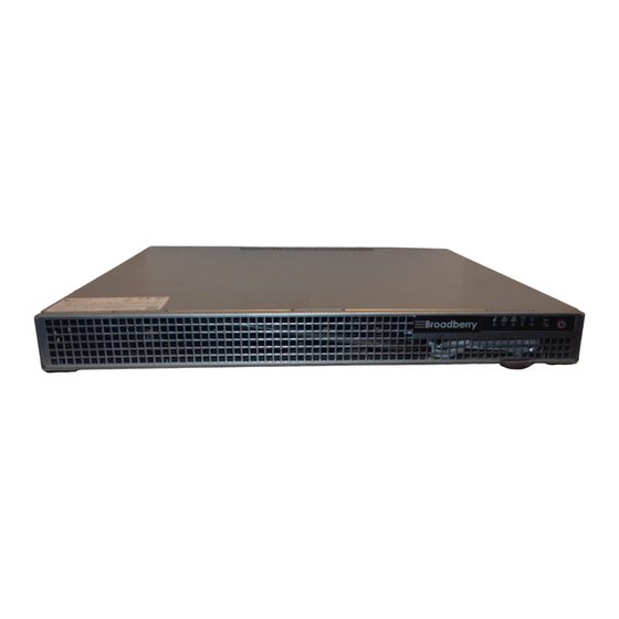
Page 6: Server Chassis Features
SuperServer 1019S-WR User's Manual Chapter 1: Introduction 1.4 Server Chassis Features Front Features The SC514-R407W is a 1U chassis See the illustration below for the features included on the front of the chassis. Control Panel The switches and LEDs located on the control panel are described below. See Chapter 4 for details on the control panel connections. -
Page 7: Rear Features
SuperServer 1019S-WR User's Manual Chapter 1: Introduction 1.5 Motherboard Layout Rear Features Below is a layout of the X11SSW-F with jumper, connector and LED locations shown. See the table on the following pages for descriptions. For detailed descriptions, pinout information The illustration below shows the features included on the rear of the chassis. -
Page 8: Quick Reference Table
+12V 8-pin CPU Power Connector JSD1/JSD2 SATA Disk On Module (DOM) Power Connectors JSTBY1 Standby Power Header JSXB1A/1B/1C Supermicro Proprietary WIO_L (Left) Add-On Card Slot JSXB2 Supermicro Proprietary WIO_R (Right) Add-On Card Slot JTPM1 Trusted Platform Module (TPM)/Port 80 Connector JUIDB1... - Page 9 SuperServer 1019S-WR User's Manual Figure 1-5. C236 Chipset: System Block Diagram IMVP 8 3 PHASE for Vcore #B-2 1 PHASE for VSA #B-1 #A-2 #A-1 PCI-E X16 8.0 Gb/S Skt-H4 SXB1 PCIe 3.0 x16 #0-15 LGA1151 DMI3 DMI3 x4 PCI-E X4 8.0 Gb/S PCIe3.0 x4 (in x8)
-
Page 10: Chapter 2 Server Installation
SuperServer 1019S-WR User's Manual Chapter 2: Server Installation Chapter 2 • In single rack installations, stabilizers should be attached to the rack. In multiple rack in- stallations, the racks should be coupled together. • Always make sure the rack is stable before extending a server or other component from Server Installation the rack. -
Page 11: Circuit Overloading
SuperServer 1019S-WR User's Manual Chapter 2: Server Installation 2.3 Installing the Rails Circuit Overloading Consideration should be given to the connection of the equipment to the power supply circuitry There are a variety of rack units on the market, which may require a slightly different assembly and the effect that any possible overloading of circuits might have on overcurrent protection procedure. -
Page 12: Assembling The Outer Rails
SuperServer 1019S-WR User's Manual Chapter 2: Server Installation Assembling the Outer Rails Installing the Outer Rails onto the Rack Each outer rail comes in two sections that must be assembled before mounting onto the rack. Each end of the assembled outer rail includes a bracket with square pegs to fit into your rack Assembling the Outer Rails holes. -
Page 13: Installing The Server Into The Rack
SuperServer 1019S-WR User's Manual Chapter 2: Server Installation Installing the Server into the Rack Installing the Server into a Telco Rack 1. Align the chassis rails with the front of the rack rails. Optional brackets (p/n MCP-290-00016-0N) are needed to install the server to a Telco (two post type) rack. -
Page 14: Chapter 3 Maintenance And Component Installation
Chapter 3: Maintenance and Component Installation Chapter 3 Maintenance and Component Installation This chapter provides instructions on installing and replacing main system components. To prevent compatibility issues, only use components that match the specifications and/or part numbers given. Installation or replacement of most components require that power first be removed from the system. -
Page 15: Motherboard Components
CPU socket cap is in place and none of the socket pins are bent; otherwise, contact your retailer immediately. • Refer to the Supermicro website for updates on CPU support. Installing the Processor(s) Begin by removing power from the system as described in Section 3.1. - Page 16 SuperServer 1019S-WR User's Manual Chapter 3: Maintenance and Component Installation 3. Add the two remaining screws then finish the installation by fully tightening all four screws (be careful not to overtighten). Screw#2 Screw#1 Figure 3-4. Inspecting the Processor Installation 4. Once aligned, carefully place the processor into the socket. Do not drop the processor...
-
Page 17: Memory Installation
Populating these DIMM slots with memory modules of the same type and size will result in interleaved memory, which will improve memory performance. Check the Supermicro website for possible updates to memory support. Installing Memory Begin by removing power from the system as described in Section 3.1. -
Page 18: Chassis Components
SuperServer 1019S-WR User's Manual Chapter 3: Maintenance and Component Installation 3.4 Chassis Components Hard Drives The 1019S-WR supports two fixed 2.5" hard disk drives with the use of a hard drive bracket (included with the system). Installing Hard Disk Drives 1. -
Page 19: Power Supply
SuperServer 1019S-WR User's Manual Chapter 4: Motherboard Connections Chapter 4 Processor Power Connector JPW2 must also be connected to the power supply. This connector is used to power the processor(s). Motherboard Connections +12V 8-pin Power Pin Definitions This section describes the connections on the motherboard and provides pinout definitions. - Page 20 SuperServer 1019S-WR User's Manual Chapter 4: Motherboard Connections Power LED/Speaker Standby Power Pins 1-3 of the JD1 header are used for power LED indication and pins 4-7 are for the speaker. The +5V Standby Power header is designated JSTBY1. You must have a card with a Standby Please note that the speaker connector pins (4-7) are for an external speaker.
-
Page 21: Control Panel
Note: UID can also be triggered via IPMI on the motherboard. For more information on IPMI, Power Button please refer to the IPMI User's Guide posted on our website at http://www.supermicro.com. Pin Definitions (JF1) Pin#... -
Page 22: Data Cables
SuperServer 1019S-WR User's Manual Chapter 4: Motherboard Connections Power Fail LED Power LED The Power Fail LED connection is located on pins 5 and 6 of JF1. The Power LED connection is located on pins 15 and 16 of JF1. -
Page 23: Ports
Two USB 2.0 ports (USB0/1) and two USB 3.0 ports (USB6/7) are located on the I/O back Supermicro SATADOMs that require an external power supply white connector). panel. The motherboard also has two front access USB 2.0 headers (USB2/3 and USB4/5) and one front access USB 3.0 header (USB9/10). -
Page 24: Jumpers
SuperServer 1019S-WR User's Manual Chapter 4: Motherboard Connections 4.4 Jumpers VGA Enable/Disable JPG1 allows you to enable or disable the VGA port. The default setting is Enabled. Explanation of Jumpers To modify the operation of the motherboard, jumpers are used to choose between optional... -
Page 25: Led Indicators
SuperServer 1019S-WR User's Manual Chapter 4: Motherboard Connections 4.5 LED Indicators SMBus to PCI Slots Jumpers JI C1 and JI C2 allow you to connect the System Management Bus (I C) to the PCI-E/PCI slots. The default setting is Open (Disabled.) Both jumpers must be set to the same... -
Page 26: Chapter 5 Software
SuperServer 1019S-WR User's Manual Chapter 5: Software Chapter 5 5.2 Driver Installation The Supermicro FTP site contains drivers and utilities for your system at ftp://ftp.supermicro. com. Some of these must be installed, such as the chipset driver. Software After accessing the FTP site, go into the CDR_Images directory and locate the ISO file for your motherboard. -
Page 27: Superdoctor ® 5
5.4 IPMI ® The Supermicro SuperDoctor 5 is a program that functions in a command-line or web-based The X11SSW-F support the Inteliigent Platform Management Interface (IPMI). IPMI is used interface for Windows and Linux operating systems. The program monitors such system health to provide remote access, monitoring and management. -
Page 28: Chapter 6 Bios
SuperServer 1019S-WR User's Manual Chapter 6: BIOS Chapter 6 6.2 Main Setup When you first enter the AMI BIOS setup utility, you will enter the Main setup screen. You can always return to the Main setup screen by selecting the Main tab on the top of the screen. -
Page 29: Advanced Setup Configurations
SuperServer 1019S-WR User's Manual Chapter 6: BIOS 6.3 A dvanced Setup Configurations Memory Information Total Memory Use the arrow keys to select Boot Setup and press <Enter> to access the submenu items. This item displays the total size of memory available in the system. - Page 30 SuperServer 1019S-WR User's Manual Chapter 6: BIOS Wait For 'F1' If Error CPU Configuration Use this feature to force the system to wait until the 'F1' key is pressed if an error occurs. The following CPU information will display: The options are Disabled and Enabled.
- Page 31 SuperServer 1019S-WR User's Manual Chapter 6: BIOS Active Processor Cores Package Power Limit MSR Lock This feature determines how many CPU cores will be activated for each CPU. When all Select Enabled to lock the package power limit for the model specific registers. The options is selected, all cores in the CPU will be activated.
- Page 32 SuperServer 1019S-WR User's Manual Chapter 6: BIOS C-State Auto Demotion Chipset Configuration Use this feature to prevent unnecessary excursions into the C-states to improve latency. The Warning: Setting the wrong values in the following features may cause the system to malfunc- options are Disabled, C1, C3, and C1 and C3.
- Page 33 SuperServer 1019S-WR User's Manual Chapter 6: BIOS DMI VC1 Control SLOT2 Max Link Speed Use this feature to enable or disable DMI Virtual Channel 1. The options are Enabled and Use this item to configure the link speed of a PCI-E port specified by the user. The options Disabled.
- Page 34 SuperServer 1019S-WR User's Manual Chapter 6: BIOS Max TOLUD Peer Memory Write Enable This feature sets the maximum TOLUD value, which specifies the "Top of Low Usable Use this feature to enable or disable peer memory write. The options are Disabled or DRAM"...
- Page 35 SuperServer 1019S-WR User's Manual Chapter 6: BIOS SATA Frozen CPU SLOT1 PCI-E 3.0 X16 OPROM Use this item to enable the HDD Security Frozen Mode. The options are Enabled and Use this feature to select which firmware type to be loaded for the add-on card in this slot.
- Page 36 SuperServer 1019S-WR User's Manual Chapter 6: BIOS Serial Port 2 Change Settings Super IO Configuration This feature specifies the base I/O port address and the Interrupt Request address of a serial The following Super IO information will display: port specified by the user. Select Auto to allow the BIOS to automatically assign the base •...
- Page 37 SuperServer 1019S-WR User's Manual Chapter 6: BIOS COM1 Console Redirection Settings COM1 Recorder Mode Select Enabled to capture the data displayed on a terminal and send it as text messages to This feature allows the user to specify how the host computer will exchange data with the a remote server.
- Page 38 SuperServer 1019S-WR User's Manual Chapter 6: BIOS COM2 Bits Per second COM2 Putty KeyPad Use this feature to set the transmission speed for a serial port used in Console Redirection. This feature selects Function Keys and KeyPad settings for Putty, which is a terminal emulator Make sure that the same speed is used in the host computer and the client computer.
- Page 39 SuperServer 1019S-WR User's Manual Chapter 6: BIOS Flow Control Pending TPM operation Use this item to set the flow control for Console Redirection to prevent data loss caused by Use this item to schedule a TPM-related operation to be performed by a security device for buffer overflow.
- Page 40 SuperServer 1019S-WR User's Manual Chapter 6: BIOS Intel I210 Gigabit Network Connection - 00:25:90:5D:3D:14 Virtual MAC Address This item displays the Virtual MAC address for this computer. Mac addresses are 6 two-digit hexadecimal numbers. NIC Configuration Intel I210 Gigabit Network Connection - 00:25:90:5D:3D:15 ...
-
Page 41: Event Logs
SuperServer 1019S-WR User's Manual Chapter 6: BIOS 6.4 Event Logs Link Status This item displays the connection status. Use this feature to configure Event Log settings. MAC Address This item displays the MAC address for this computer. Mac addresses are 6 two-digit hexadecimal numbers. -
Page 42: Ipmi
SuperServer 1019S-WR User's Manual Chapter 6: BIOS 6.5 IPMI SMBIOS Event Long Standard Settings Log System Boot Event Use this feature to configure Intelligent Platform Management Interface (IPMI) settings. This option toggles the System Boot Event logging to enabled or disabled. The options are Disabled and Enabled. - Page 43 SuperServer 1019S-WR User's Manual Chapter 6: BIOS When SEL is Full Station MAC Address This feature allows the user to decide what the BIOS should do when the system event log This item displays the Station MAC address for this computer. Mac addresses are 6 two-digit is full.
-
Page 44: Security
SuperServer 1019S-WR User's Manual Chapter 6: BIOS 6.6 Security Secure Boot Mode Use this item to select the secure boot mode. The options are Standard and Custom. This menu allows the user to configure the following security settings for the system. - Page 45 SuperServer 1019S-WR User's Manual Chapter 6: BIOS 6.7 Boot Append Key Select Yes to add the database from the manufacturer's defaults to the existing DB. Select Use this feature to configure Boot Settings: No to load the DB from a file. The options are Yes and No.
- Page 46 SuperServer 1019S-WR User's Manual Chapter 6: BIOS • 6.8 Save & Exit Legacy/UEFI/Dual/Boot Order #8 Select the Exit tab from the BIOS setup utility screen to enter the Exit BIOS Setup screen. • Legacy/UEFI/Dual/Boot Order #9 • Legacy/UEFI/Dual/Boot Order #10 •...
- Page 47 SuperServer 1019S-WR User's Manual Default Options Restore Optimized Defaults To set this feature, select Restore Optimized Defaults from the Save & Exit menu and press <Enter>. These are factory settings designed for maximum system stability, but not for maximum performance.
-
Page 48: Bios Error Codes
Appendix A: BIOS Error Codes Appendix A BIOS Error Codes A-1 BIOS Error Beep (POST) Codes During the POST (Power-On Self-Test) routines, which are performed each time the system is powered on, errors may occur. Non-fatal errors are those which, in most cases, allow the system to continue the boot-up process. - Page 49 Este símbolo de aviso indica peligro. Existe riesgo para su integridad física. Antes de Read this appendix in its entirety before installing or configuring components in the Supermicro manipular cualquier equipo, considere los riesgos de la corriente eléctrica y familiarícese chassis.
- Page 50 SuperServer 1019S-WR User's Manual Appendix B: Standardized Warning Statements Warnung جسذٌة اصابة ًتتسبب ف حالة ٌوكي أى ًاًك ف خطز ًٌٌع هذا الزهز !تحذٌز Vor dem Anschließen des Systems an die Stromquelle die Installationsanweisungen lesen. الذوائز بالوخاطز الٌاجوة عي ي على علن...
- Page 51 SuperServer 1019S-WR User's Manual Appendix B: Standardized Warning Statements Power Disconnection Warning Warnung Dieses Produkt ist darauf angewiesen, dass im Gebäude ein Kurzschluss- bzw. Warning! The system must be disconnected from all sources of power and the power Überstromschutz installiert ist. Stellen Sie sicher, dass der Nennwert der Schutzvorrichtung cord removed from the power supply module(s) before accessing the chassis interior nicht mehr als: 250 V, 20 A beträgt.
- Page 52 SuperServer 1019S-WR User's Manual Appendix B: Standardized Warning Statements Attention امداد وحدة من سهك انكهرباء وإزانت انطاقت مصادر من جميع اننظاو يجب فصم Il est vivement recommandé de confier l'installation, le remplacement et la maintenance de ces équipements à des personnels qualifiés et expérimentés.
- Page 53 SuperServer 1019S-WR User's Manual Appendix B: Standardized Warning Statements Battery Handling Warnung Diese Einheit ist zur Installation in Bereichen mit beschränktem Zutritt vorgesehen. Der Zutritt zu derartigen Bereichen ist nur mit einem Spezialwerkzeug, Schloss und Schlüssel oder einer Warning! There is the danger of explosion if the battery is replaced incorrectly. Replace sonstigen Sicherheitsvorkehrung möglich.
- Page 54 SuperServer 1019S-WR User's Manual Appendix B: Standardized Warning Statements ¡Advertencia! فعليل بطريقة غير صحيحة البطارية انفجار في حالة اسحبذال من هناك خطر Puede que esta unidad tenga más de una conexión para fuentes de alimentación. Para cortar اسحبذال البطارية por completo el suministro de energía, deben desconectarse todas las conexiones.
- Page 55 SuperServer 1019S-WR User's Manual Appendix B: Standardized Warning Statements Backplane Voltage اللىحة أوالطاقة المىجىدة على التيار الكهزبائي مه خطز هناك هذا الجهاس خدمة كه حذرا عند يعمل النظام عندما يكىن Warning! Hazardous voltage or energy is present on the backplane when the system is operating.
- Page 56 SuperServer 1019S-WR User's Manual Appendix B: Standardized Warning Statements תיאום חוקי החשמל הארצי Attention !אזהרה La mise au rebut ou le recyclage de ce produit sont généralement soumis à des lois et/ou הציוד חייבת להיות תואמת לחוקי החשמל המקומיים והארציים...
- Page 57 섀시로부터 팬 조립품을 제거할 때 팬은 여전히 회전하고 있을 수 있습니다. 팬 조림품 Verwendung von UL-oder CSA-zertifizierte Kabel, UL oder CSA auf der Code für alle anderen 외관의 열려있는 부분들로부터 손가락 및 스크류드라이버, 다른 물체들이 가까이 하지 elektrischen Geräte als Produkte von Supermicro nur bezeichnet gezeigt haben. 않도록 배치해 주십시오. Waarschuwing ¡Advertencia!
- Page 58 Het gebruik van andere kabels en adapters kan leiden tot een storing of een brand. Elektrisch apparaat en veiligheidsinformatiebladen wet verbiedt het gebruik van UL of CSA gecertificeerde kabels die UL of CSA die op de code voor andere elektrische apparaten dan de producten die door Supermicro alleen.
- Page 59 Appendix C: System Specifications Appendix C System Specifications Processors Single Intel® Xeon® E3-1200 v5 and 6th Gen Core™ i3, Pentium and Celeron in an LGA1151 (H4) type socket Note: Please refer to the motherboard specifications pages on our website for updates to supported processors. Chipset Intel C236 chipset BIOS...
- Page 60 SuperServer 1019S-WR User's Manual Regulatory Compliance Electromagnetic Emissions: FCC Class A, EN 55022 Class A, EN 61000-3-2/3-3, CISPR 22 Class A Electromagnetic Immunity: EN 55024/CISPR 24, (EN 61000-4-2, EN 61000-4-3, EN 61000-4-4, EN 61000-4-5, EN 61000-4-6, EN 61000-4-8, EN 61000-4-11)
Need help?
Do you have a question about the SuperServer 1019S-WR and is the answer not in the manual?
Questions and answers