Table of Contents
Advertisement
The information in this User's Manual has been carefully reviewed and is believed to be accurate. The vendor assumes
no responsibility for any inaccuracies that may be contained in this document, and makes no commitment to update
or to keep current the information in this manual, or to notify any person or organization of the updates. Please Note:
For the most up-to-date version of this manual, please see our website at www.supermicro.com.
Super Micro Computer, Inc. ("Supermicro") reserves the right to make changes to the product described in this manual
at any time and without notice. This product, including software and documentation, is the property of Supermicro and/
or its licensors, and is supplied only under a license. Any use or reproduction of this product is not allowed, except
as expressly permitted by the terms of said license.
IN NO EVENT WILL Super Micro Computer, Inc. BE LIABLE FOR DIRECT, INDIRECT, SPECIAL, INCIDENTAL,
SPECULATIVE OR CONSEQUENTIAL DAMAGES ARISING FROM THE USE OR INABILITY TO USE THIS PRODUCT
OR DOCUMENTATION, EVEN IF ADVISED OF THE POSSIBILITY OF SUCH DAMAGES. IN PARTICULAR, SUPER
MICRO COMPUTER, INC. SHALL NOT HAVE LIABILITY FOR ANY HARDWARE, SOFTWARE, OR DATA STORED
OR USED WITH THE PRODUCT, INCLUDING THE COSTS OF REPAIRING, REPLACING, INTEGRATING,
INSTALLING OR RECOVERING SUCH HARDWARE, SOFTWARE, OR DATA.
SuperServer
®
Any disputes arising between manufacturer and customer shall be governed by the laws of Santa Clara County in the
State of California, USA. The State of California, County of Santa Clara shall be the exclusive venue for the resolution
5019P-WT
of any such disputes. Supermicro's total liability for all claims will not exceed the price paid for the hardware product.
FCC Statement: This equipment has been tested and found to comply with the limits for a Class A digital device
5019P-WTR
pursuant to Part 15 of the FCC Rules. These limits are designed to provide reasonable protection against harmful
interference when the equipment is operated in a commercial environment. This equipment generates, uses, and can
radiate radio frequency energy and, if not installed and used in accordance with the manufacturer's instruction manual,
may cause harmful interference with radio communications. Operation of this equipment in a residential area is likely
to cause harmful interference, in which case you will be required to correct the interference at your own expense.
California Best Management Practices Regulations for Perchlorate Materials: This Perchlorate warning applies only
to products containing CR (Manganese Dioxide) Lithium coin cells. "Perchlorate Material-special handling may apply.
See www.dtsc.ca.gov/hazardouswaste/perchlorate".
WARNING: Handling of lead solder materials used in this product may expose you to lead, a
chemical known to the State of California to cause birth defects and other reproductive harm.
The products sold by Supermicro are not intended for and will not be used in life support systems, medical equipment,
nuclear facilities or systems, aircraft, aircraft devices, aircraft/emergency communication devices or other critical
systems whose failure to perform be reasonably expected to result in significant injury or loss of life or catastrophic
property damage. Accordingly, Supermicro disclaims any and all liability, and should buyer use or sell such products
for use in such ultra-hazardous applications, it does so entirely at its own risk. Furthermore, buyer agrees to fully
indemnify, defend and hold Supermicro harmless for and against any and all claims, demands, actions, litigation, and
proceedings of any kind arising out of or related to such ultra-hazardous use or sale.
Manual Revision 1.0
Release Date: August 02, 2017
Unless you request and receive written permission from Super Micro Computer, Inc., you may not copy any part of this
document. Information in this document is subject to change without notice. Other products and companies referred
to herein are trademarks or registered trademarks of their respective companies or mark holders.
USER'S MANUAL
Copyright © 2017 by Super Micro Computer, Inc.
All rights reserved.
Revision 1.0
Printed in the United States of America
Advertisement
Table of Contents

Related Manuals for Supermicro SuperServer 5019P-WT


Summary of Contents for Supermicro SuperServer 5019P-WT
- Page 1 5019P-WT of any such disputes. Supermicro's total liability for all claims will not exceed the price paid for the hardware product. FCC Statement: This equipment has been tested and found to comply with the limits for a Class A digital device 5019P-WTR pursuant to Part 15 of the FCC Rules.
- Page 2 This manual is written for professional system integrators and PC technicians. It provides 1.3 System Features ........................9 information for the installation and use of the SuperServer 5019P-WT/WTR. Installation and maintainance should be performed by experienced technicians only. 1.4 Server Chassis Features ....................10 Please refer to the 5019P-WT/WTR server specifications page on our website for updates on Control Panel ........................10...
- Page 3 SuperServer 5019P-WT/WTR User's Manual Preface 3.3 Motherboard Components ....................25 4.3 Ports and Headers ......................50 Processor and Heatsink Installation ..................25 Rear I/O Ports ........................50 The Intel Xeon 81xx/61xx/51xx/41xx/31xxSeries Processor ...........25 Connectors ........................53 Overview of the Processor Socket Assembly ..............26 Headers ..........................54 Overview of the Processor Heatsink Module (PHM) ............27...
-
Page 4: Contacting Supermicro
Super Micro Computer, Inc. 980 Rock Ave. San Jose, CA 95131 U.S.A. Tel: +1 (408) 503-8000 Fax: +1 (408) 503-8008 Email: marketing@supermicro.com (General Information) support@supermicro.com (Technical Support) Website: www.supermicro.com Europe Address: Super Micro Computer B.V. Het Sterrenbeeld 28, 5215 ML... -
Page 5: System Features
1.2 Unpacking the System Four 3.5" hot-swap hard drives and one (1) M.2 connector x4 (22110/2280) Inspect the box the SuperServer 5019P-WT/WTR was shipped in and note if it was damaged Power in any way. If any equipment appears damaged, please file a damage claim with the carrier 5019P-WT: single 600W power supply module who delivered it. -
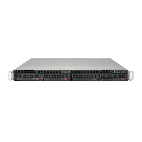
Page 6: Server Chassis Features
SuperServer 5019P-WT/WTR User's Manual Chapter 1: Introduction 1.4 Server Chassis Features Chassis Front The 815TQC-605WB/R504WB is a 1U rackmount chassis See the illustration below for the features included on the front of the chassis. Control Panel The switches and LEDs located on the control panel are described below. See Chapter 4 for details on the control panel connections. -
Page 7: Chassis Rear
SuperServer 5019P-WT/WTR User's Manual Chapter 1: Introduction Chassis Rear 1.5 Motherboard Layout The illustration below shows the features included on the rear of the chassis. Below is a layout of the X11SPW-TF with jumper, connector and LED locations shown. See Note: the 5019P-WTR and 5019P-WT servers are shown below. -
Page 8: Quick Reference Table
S-SATA0~1 SATA 3.0 Ports with SATA DOM Power JPSAS1 SAS HDD Enable/Disable Pins 1-2 (Enabled) SXB1A, SXB1B, SXB1C Supermicro Proprietary WIO Left Add-on Card Slots JPTG1 LAN Enable/Disable Pins 1-2 (Enabled) SXB2 Supermicro Proprietary WIO Right Add-on Card Slot JWD1... - Page 9 SuperServer 5019P-WT/WTR User's Manual VCCP0 12v VR13 5+1 PHASE #F-1 #C-1 205W #E-1 #B-1 #D-1 #A-1 VCCP0 SNB CORE PECI:30 DDR-IV SOCKET ID:0 DMI3 PCI-E X8 G3 DMI3 PCI-E X16 G3 PCI-E X16 G3 Uplink #0~3 PCI-E X4 G3 6.0 Gb/S M.2 SSD...
-
Page 10: Server Installation
Chapter 2: Server Installation Chapter 2 Server Installation 2.1 Overview This chapter provides advice and instructions for mounting your system in a server rack. If your system is not already fully integrated with processors, system memory etc., refer to Chapter 4 for details on installing those specific components. Caution: Electrostatic Discharge (ESD) can damage electronic components. -
Page 11: Server Precautions
SuperServer 5019P-WT/WTR User's Manual Chapter 2: Server Installation • Always make sure the rack is stable before extending a server or other component from Circuit Overloading the rack. Consideration should be given to the connection of the equipment to the power supply circuitry and the effect that any possible overloading of circuits might have on overcurrent protection •... -
Page 12: Installing The Rails
SuperServer 5019P-WT/WTR User's Manual Chapter 2: Server Installation 2.3 Installing the Rails Installing the Outer Rails Begin by measuring the distance from the front rail to the rear rail of the rack. Attach a short There are a variety of rack units on the market, which may require a slightly different assembly bracket to the front side of the right outer rail and a long bracket to the rear side of the right procedure. -
Page 13: Installing The Server Into A Rack
2.4 Installing the Server into a Rack Installing to a Telco Rack To install the SuperServer 5019P-WT/WTR into a Telco (or “open”) type rack, use two L-shaped brackets on either side of the chassis (four total). Installing to a Standard Rack 1. -
Page 14: Motherboard Components
3.2 Accessing the System heatsink only. The 815TQC-605WB/R504WB features a removable top cover, which allows easy access to • Refer to the Supermicro website for updates on CPU support. the inside of the chassis. Removing the Top Cover The Intel Xeon 81xx/61xx/51xx/41xx/31xxSeries Processor 1. -
Page 15: Overview Of The Processor Socket Assembly
SuperServer 5019P-WT/WTR User's Manual Chapter 3: Maintenance and Component Installation Overview of the Processor Socket Assembly Overview of the Processor Heatsink Module (PHM) The Processor Heatsink Module (PHM) contains 1) a heatsink, 2) a processor clip, and 3) The processor socket assembly contains 1) the Intel SKX processor, 2) the processor clip, the SKX processor. -
Page 16: Attaching The Non-F Model Processor To The Processor Clip To Create The Processor Carrier Assembly
SuperServer 5019P-WT/WTR User's Manual Chapter 3: Maintenance and Component Installation Attaching the Non-F Model Processor to the Processor Clip to Attaching the Non-F Model Processor Carrier Assembly to the Create the Processor Carrier Assembly Heatsink to Form the Processor Heatsink Module (PHM) -
Page 17: Preparing The Cpu Socket For Installation
SuperServer 5019P-WT/WTR User's Manual Chapter 3: Maintenance and Component Installation Preparing the CPU Socket for Installation Installing the Processor Heatsink Module (PHM) This motherboard comes with the CPU socket pre-assembled in the factory. The CPU socket Once you have assembled the processor heatsink module (PHM) by following the instructions contains 1) a dust cover, 2) a socket bracket, 3) the CPU (P0) socket, and 4) a back plate. -
Page 18: Memory Installation
LRDIMM 3DS 8Rx1 4H-128 GB 2666 2666 2666 Note: Visit the product page on the Supermicro website for possible updates to memory support (www.supermicro.com). CPU Socket After removing the screws, lift the Processor Heatsink Printed Triangle on Motherboard Module off the CPU socket. -
Page 19: Dimm Module Population Sequence
SuperServer 5019P-WT/WTR User's Manual Chapter 3: Maintenance and Component Installation DIMM Module Population Sequence DIMM Installation JUIDB1 COM1 JIPMB1 1. Insert the desired number of DIMMs USB7/8(3.0) When installing memory modules, the DIMM slots must be populated in the following order:... -
Page 20: Pci Expansion Card Installation
SuperServer 5019P-WT/WTR User's Manual Chapter 3: Maintenance and Component Installation PCI Expansion Card Installation The system includes two pre-installed riser cards (p/n CSE-RR1U-E8 and RSC-R1UW-2E16) that positions standard size PCI-E cards at a 90 degree angle, allowing them to fit inside the chassis. -
Page 21: Chassis Components
SuperServer 5019P-WT/WTR User's Manual Chapter 3: Maintenance and Component Installation Daughter Cards 3.4 Chassis Components An IPMI card can be installed into the motherboard for remote management capabilities. See the board layout for the location of the daughter board connector. - Page 22 Figure 3-5. Removing a Drive Carrier Amber Blinking at 1 Hz Attention state—do not remove NVMe device Note: Enterprise level hard disk drives are recommended for use in Supermicro chassis and servers. For information on recommended HDDs, visit the Supermicro website at http://www. supermicro.com/products/nfo/files/storage/SBB-HDDCompList.pdf...
-
Page 23: System Cooling
SuperServer 5019P-WT/WTR User's Manual Chapter 3: Maintenance and Component Installation Caution: Use caution when working around the hard drive backplane. Do not touch the backplane with any metal objects and make sure no ribbon cables touch the backplane or obstruct the holes, which aid in proper airflow. -
Page 24: Power Supply
SuperServer 5019P-WT/WTR User's Manual Chapter 3: Maintenance and Component Installation Power Supply The SC815TQC chassis comes equipped either with a 600 Watt (5019P-WT) or with two redundant 500 Watt (5019P-WTR) hot-plug power supplies. These power supplies are auto- switching capable and automatically sense and operate at a 100v to 240v input voltage. An amber light will be illuminated on the power supply when the power is off. -
Page 25: Motherboard Connections
SuperServer 5019P-WT/WTR User's Manual Chapter 4: Motherboard Connections Chapter 4 Main ATX Power Connector The primary power connector (JPWR1) meets the ATX SSI EPS 24-pin specification. You must also connect the 8-pin (JPWR2) processor power connector to your power supply (see below). -
Page 26: Front Control Panel
These connectors are designed specifically for use PWR Fail LED with Supermicro chassis. See the figure below for the descriptions of the front control panel Pin Definitions (JF1) buttons and LED indicators. -
Page 27: Ports And Headers
Note: UID can also be triggered via IPMI on the motherboard. For more information on IPMI, please refer to the IPMI User's Guide posted on our website at http://www.supermicro.com. Rear I/O Ports... -
Page 28: Connectors
SuperServer 5019P-WT/WTR User's Manual Chapter 4: Motherboard Connections Connectors Universal Serial Bus (USB) Ports There are two USB 2.0 ports (USB0/1) and two USB 3.0 ports (USB7/8) on the I/O back panel. Disk-On-Module Power Connector The motherboard also has three front access USB 2.0 headers (USB2/3, USB4/5, USB6) and The Disk-On-Module (DOM) power connectors at JSD1 and JSD2 provide 5V power to a one front access USB 3.0 header (USB10/11). -
Page 29: Headers
SuperServer 5019P-WT/WTR User's Manual Chapter 4: Motherboard Connections Headers Standby Power Fan Headers The Standby Power header is located at JSTBY1 on the motherboard. See the table below for pin definitions. There are seven fan headers on the motherboard. These are 4-pin fan headers; pins 1-3 are backward compatible with traditional 3-pin fans. -
Page 30: Jumpers
SuperServer 5019P-WT/WTR User's Manual Chapter 4: Motherboard Connections 4.4 Jumpers Overheat/Fan Fail LED Header Connect an LED indicator to JOH1 to display warnings of chassis overheating and fan failure. See the table below for the LED status. Explanation of Jumpers... -
Page 31: Led Indicators
SuperServer 5019P-WT/WTR User's Manual Chapter 4: Motherboard Connections 4.5 LED Indicators VGA Enable/Disable JPG1 allows you to enable or disable the VGA port using the onboard graphics controller. LAN LEDs The default setting is Enabled. Two LAN ports (LAN 1 and LAN 2) are located on the I/O back panel of the motherboard. - Page 32 SuperServer 5019P-WT/WTR User's Manual BMC Heartbeat LED LEDM1 is the BMC heartbeat LED. When the LED is blinking green, BMC is functioning normally. See the table below for the LED status. BMC Heartbeat LED Indicator LED Color Definition Green: BMC Normal...
-
Page 33: Installing The Windows Os For A Raid System
You must first configure RAID settings (if using RAID) before you install the Windows OS and the software drivers. To configure RAID settings, please refer to the RAID Configuration User Guides posted on our website at www.supermicro.com/support/manuals. Installing the Windows OS for a RAID System 1. -
Page 34: Driver Installation
The Supermicro FTP site contains drivers and utilities for your system at ftp://ftp.supermicro. The Supermicro SuperDoctor 5 is a program that functions in a command-line or web-based com. Some of these must be installed, such as the chipset driver. interface for Windows and Linux operating systems. The program monitors such system health... -
Page 35: Ipmi
SuperServer 5019P-WT/WTR User's Manual 5.4 IPMI The X11SPW-TF supports the Inteliigent Platform Management Interface (IPMI). IPMI is used to provide remote access, monitoring and management. There are several BIOS settings that are related to IPMI. For general documentation and information on IPMI, please visit our website at:... -
Page 36: Starting The Setup Utility
Chapter 6: BIOS Chapter 6 BIOS 6.1 Introduction This chapter describes the AMIBIOS™ Setup utility for the X11SPW-TF motherboard(s). The is stored in a flash chip and can be easily upgraded using a floppy disk-based program. Note: Due to periodic changes to the BIOS, some settings may have been added or deleted and might not yet be recorded in this manual. -
Page 37: Main Menu
SuperServer 5019P-WT/WTR User's Manual Chapter 6: BIOS 6.2 Main Menu Supermicro X11SPW-TF BIOS Version When you first enter AMI BIOS Setup Utility, you will see the Main Menu screen. You can always return to the Main Menu by selecting the Main tab on the top of the screen with the This item displays the version of the BIOS ROM used in the system. -
Page 38: Advanced Setup Configurations
SuperServer 5019P-WT/WTR User's Manual Chapter 6: BIOS 6.3 Advanced Setup Configurations Bootup NumLock State Use this feature to set the Power-on state for the <Numlock> key. The options are On and Off. Use the arrow keys to select Boot Setup and press <Enter> to access the submenu items. -
Page 39: Security
SuperServer 5019P-WT/WTR User's Manual Chapter 6: BIOS Power Button Function Intel Virtualization Technology This feature controls how the system shuts down when the power button is pressed. Select 4 Use this feature to enable the Vanderpool Technology. This technology allows the system to Seconds Override for the user to power off the system after pressing and holding the power run several operating systems simultaneously. - Page 40 SuperServer 5019P-WT/WTR User's Manual Chapter 6: BIOS Advanced Power Management Configuration CPU C6 Report Select Enable to allow the BIOS to report the CPU C6 State (ACPI C3) to the operating system. During the CPU C6 State, the power to all cache is turned off. The options are ...
- Page 41 SuperServer 5019P-WT/WTR User's Manual Chapter 6: BIOS Chipset Configuration Isoc Mode Isochronous (Isoc) mode allows time-sensitive processes to be given priority. The options Warning: Setting the wrong values in the following features may cause the system to malfunc- are Disable, Enable, and Auto.
- Page 42 SuperServer 5019P-WT/WTR User's Manual Chapter 6: BIOS Patrol Scrub Interval Memory RAS Configuration This feature allows you to decide how many hours the system should wait before the Static Virtual Lockstep Mode next complete patrol scrub is performed. Use the keyboard to enter a value from 0-24.
- Page 43 SuperServer 5019P-WT/WTR User's Manual Chapter 6: BIOS Prioritize TPH ntel® VMD Technology Use this feature to enable Prioritize TPH support. The options are Enable and Disable. Intel® VMD for Volume Management Device on CPU Relaxed Ordering Select Enable to enable Relaxed Ordering support, which will allow certain transac-...
- Page 44 SuperServer 5019P-WT/WTR User's Manual Chapter 6: BIOS Server ME Configuration SATA RAID Option ROM/UEFI Driver Select UEFI to load the EFI driver for system boot. Select Legacy to load a legacy driver for The following General ME Configuration will display: system boot.
- Page 45 SuperServer 5019P-WT/WTR User's Manual Chapter 6: BIOS Aggressive Link Power Management PCIe/PCI/PnP Configuration When this item is set to Enable, the SATA AHCI controller manages the power usage of the The following information will display: SATA link. The controller will put the link in a low power mode during extended periods of I/O •...
- Page 46 SuperServer 5019P-WT/WTR User's Manual Chapter 6: BIOS VGA Priority IPv6 HTTP Support Use this feature to select VGA priority when multiple VGA devices are detected. Select On- Select Enabled to enable IPv6 HTTP boot support. The options are Disabled and Enabled.
- Page 47 SuperServer 5019P-WT/WTR User's Manual Chapter 6: BIOS Device Settings COM1 Data Bits This item displays the status of a serial part specified by the user. Use this feature to set the data transmission size for Console Redirection. The options are 7 Bits and 8 Bits.
- Page 48 SuperServer 5019P-WT/WTR User's Manual Chapter 6: BIOS COM1 Redirection After BIOS POST COM2 Stop Bits Use this feature to enable or disable legacy console redirection after BIOS POST. When A stop bit indicates the end of a serial data packet. Select 1 Stop Bit for standard serial set to Bootloader, legacy console redirection is disabled before booting the OS.
- Page 49 SuperServer 5019P-WT/WTR User's Manual Chapter 6: BIOS EMS (Emergency Management Services) Console Redirection High Precision Event Timer Select Enabled to use a COM port selected by the user for EMS Console Redirection. The Select Enabled to activate the High Precision Event Timer (HPET) that produces periodic options are Enabled and Disabled.
-
Page 50: Event Logs
SuperServer 5019P-WT/WTR User's Manual Chapter 6: BIOS 6.4 Event Logs When Log is Full Select Erase Immediately for all messages to be automatically erased from the event log Use this feature to configure Event Log settings. when the event log memory is full. The options are Do Nothing and Erase Immediately. - Page 51 SuperServer 5019P-WT/WTR User's Manual Chapter 6: BIOS 6.5 IPMI Erase SEL Select Yes, On next reset to erase all system event logs upon next system reboot. Select Use this feature to configure Intelligent Platform Management Interface (IPMI) settings. Yes, On every reset to erase all system event logs upon each system reboot. Select No to keep all system event logs after each system reboot.
- Page 52 SuperServer 5019P-WT/WTR User's Manual Chapter 6: BIOS 6.6 Security Subnet Mask This item displays the sub-network that this computer belongs to. The value of each three- This menu allows the user to configure the following security settings for the system.
- Page 53 SuperServer 5019P-WT/WTR User's Manual Chapter 6: BIOS Secure Boot Platform Key (PK) This section displays the contents of the following secure boot features: This feature allows the user to configure the settings of the platform keys. • System Mode Set New •...
- Page 54 SuperServer 5019P-WT/WTR User's Manual Chapter 6: BIOS 6.7 Boot Authorized TimeStamps Use this feature to configure Boot Settings. Set New Select Yes to load the DBT from the manufacturer's defaults. Select No to load the DBT from a file. The options are Yes and No.
- Page 55 SuperServer 5019P-WT/WTR User's Manual Chapter 6: BIOS *If the item above is set to Legacy, UEFI, or Dual the following items will be displayed: UEFI Application Boot Priorities • Legacy/UEFI/Dual Boot Option #1 This feature allows the user to specify which UEFI devices are boot devices.
- Page 56 SuperServer 5019P-WT/WTR User's Manual Chapter 6: BIOS 6.8 Save & Exit Discard Changes Select this option and press <Enter> to discard all the changes and return to the AMI BIOS Use this feature to save, discard, and reset setting changes.
- Page 57 When BIOS performs the Power On Self Test, it writes checkpoint codes to I/O port 0080h. If the computer cannot complete the boot process, a diagnostic card can be attached to the computer to read I/O port 0080h (Supermicro p/n AOC-LPC80-20). A-1 BIOS Error Beep (POST) Codes For information on AMI updates, please refer to http://www.ami.com/products/.
- Page 58 SuperServer 5019P-WT/WTR User's Manual...
- Page 59 Este símbolo de aviso indica peligro. Existe riesgo para su integridad física. Antes de Read this appendix in its entirety before installing or configuring components in the Supermicro manipular cualquier equipo, considere los riesgos de la corriente eléctrica y familiarícese chassis.
- Page 60 SuperServer 5019P-WT/WTR User's Manual Appendix B: Standardized Warning Statements . ٌ ا ك ً ف حالة و ٌ يك أى تتسبب ف اصابة جسذ ة ٌ هذا الزهز ع ٌ خطز !تحذ ز Warnung قبل أى تعول عىل أي هعذات،يك عىل علن بالوخاطز ال ا ٌجوة عي الذوائز...
- Page 61 SuperServer 5019P-WT/WTR User's Manual Appendix B: Standardized Warning Statements Power Disconnection Warning Warnung Dieses Produkt ist darauf angewiesen, dass im Gebäude ein Kurzschluss- bzw. Warning! The system must be disconnected from all sources of power and the power Überstromschutz installiert ist. Stellen Sie sicher, dass der Nennwert der Schutzvorrichtung cord removed from the power supply module(s) before accessing the chassis interior nicht mehr als: 250 V, 20 A beträgt.
- Page 62 SuperServer 5019P-WT/WTR User's Manual Appendix B: Standardized Warning Statements يجب فصم اننظاو من جميع مصادر انطاقت وإ ز انت سهك انكهرباء من وحدة امداد Attention انطاقت قبم Il est vivement recommandé de confier l'installation, le remplacement et la maintenance de ces équipements à...
- Page 63 SuperServer 5019P-WT/WTR User's Manual Appendix B: Standardized Warning Statements Battery Handling Warnung Diese Einheit ist zur Installation in Bereichen mit beschränktem Zutritt vorgesehen. Der Zutritt zu derartigen Bereichen ist nur mit einem Spezialwerkzeug, Schloss und Schlüssel oder einer Warning! There is the danger of explosion if the battery is replaced incorrectly. Replace sonstigen Sicherheitsvorkehrung möglich.
- Page 64 SuperServer 5019P-WT/WTR User's Manual Appendix B: Standardized Warning Statements هناك خطر من انفجار يف حالة اسحبذال البطارية بطريقة غري صحيحة فعليل ¡Advertencia! اسحبذال البطارية Puede que esta unidad tenga más de una conexión para fuentes de alimentación. Para cortar por completo el suministro de energía, deben desconectarse todas las conexiones.
- Page 65 SuperServer 5019P-WT/WTR User's Manual Appendix B: Standardized Warning Statements Backplane Voltage هناك خطز مه التيار الكهزبايئ أوالطاقة املىجىدة عىل اللىحة عندما يكىن النظام يعمل كه حذ ر ا عند خدمة هذا الجهاس Warning! Hazardous voltage or energy is present on the backplane when the system is operating.
- Page 66 SuperServer 5019P-WT/WTR User's Manual Appendix B: Standardized Warning Statements תיאום חוקי החשמל הארצי Attention !אזהרה La mise au rebut ou le recyclage de ce produit sont généralement soumis à des lois et/ou .התקנת הציוד חייבת להיות תואמת לחוקי החשמל המקומיים והארציים...
- Page 67 제거할 때 팬은 여전히 회전하고 있을 수 있습니다. 팬 조림품 외관의 열려있는 부분들로부터 Feuer verursachen. Die Richtlinien untersagen das Nutzen von UL oder CAS zertifizierten 손가락 및 스크류드라이버, 다른 물체들이 가까이 하지 않도록 배치해 주십시오. Kabeln (mit UL/CSA gekennzeichnet), an Geräten oder Produkten die nicht mit Supermicro Waarschuwing gekennzeichnet sind.
- Page 68 حجم املوصل والقابس السليم. استخدام أي كابالت ومحوالت أخرى قد يتسبب يف عطل أو حريق. يحظر قانون السالمة لألجهزة الكهربائية واملعدات استخدام الكابالت املعتمدة من قبلUL أوCSA ( والتي تحمل عالمةUL/CSA) مع أي معدات أخرى غري املنتجات املعنية واملحددة من قبلSupermicro.
-
Page 69: System Specifications
Appendix C: System Specifications Appendix C System Specifications Processors Single Intel Xeon 81xx/61xx/51xx/41xx/31xx processor in an Socket P0-LGA3647 Note: Please refer to the motherboard specifications pages on our website for updates to supported processors. Chipset Intel PCH C622 chipset BIOS 256 Mb AMI®... - Page 70 SuperServer 5019P-WT/WTR User's Manual Regulatory Compliance Electromagnetic Emissions: FCC Class B, EN 55022 Class B, EN 61000-3-2/3-3, CISPR 22 Class B Electromagnetic Immunity: EN 55024/CISPR 24, (EN 61000-4-2, EN 61000-4-3, EN 61000-4-4, EN 61000-4-5, EN 61000-4-6, EN 61000-4-8, EN 61000-4-11)
- Page 71 Warning: Do not upgrade the BIOS unless your system has a BIOS-related issue. Flashing the wrong BIOS can cause irreparable damage to the system. In no event shall Supermicro be liable for direct, indirect, special, incidental, or consequential damages arising from a BIOS update.
- Page 72 SuperServer 5019P-WT/WTR User's Manual Appendix D: UEFI BIOS Recovery The file system supported by UEFI is FAT (including FAT12, FAT16, and FAT32) which is Warning: Please stop pressing the <Ctrl> and <Home> keys immediately when you see the installed on a bootable or non-bootable USB-attached device. However, the BIOS might need several minutes to locate the SUPER.ROM file if the media size becomes too large due to...
- Page 73 SuperServer 5019P-WT/WTR User's Manual Appendix D: UEFI BIOS Recovery 5. When the screen as shown above displays, use the arrow keys to select the item 8. Press <Del> continuously during system boot to enter the BIOS setup utility. From the top of the tool bar, click on Boot and press <Enter>...
Need help?
Do you have a question about the SuperServer 5019P-WT and is the answer not in the manual?
Questions and answers