Table of Contents

Related Manuals for Univex SRM30+


Summary of Contents for Univex SRM30+
- Page 1 SRM30+ PLANETARY MIXER PARTS AND SERVICE MANUAL Persons under the age of 18 are not permitted to operate or have access to this equipment per U.S. Dept. Of Labor Employment Standards Administration Sheet No. ESA913 SRM30 SERVICE REV D...
-
Page 2: Table Of Contents
TABLE OF CONTENTS DESCRIPTION PAGE TABLE OF CONTENTS......................I LIST OF ILLUSTRATIONS.....................II TROUBLE SHOOTING GUIDE ...................1.1 MECHANICS MAINTENANCE BELTS..........................2.1 MOTOR ..........................2.2 BOWL LIFT ADJUSTMENT...................2.2 LUBRICATION........................2.3 REMOVAL OF TOP COVER ..................2.4 TRANSMISSION REMOVAL ........................3.1 TRANSMISSION PARTS LIST..................3.2 BEATER HEAD ASSEMBLY..................3.3 BEATER HEAD PARTS LIST ..................3.4 INPUTASSEMBLY ASSEMBLY..................3.5 INPUTASSEMBLY PARTS LIST ...................3.6 POWER TAKE OFF ASSEMBLY ...................3.7... -
Page 3: List Of Illustrations
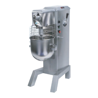
LIST OF ILLUSTRATIONS DESCRIPTION PAGE FIGURE 1 OVERALL VIEW OF MIXER..................III FIGURE 2 LUBRICATION DIAGRAM..................2.3 FIGURE 3 TRANSMISSION ASSEMBLY .................3.2 FIGURE 4 BEATER HEAD ASSEMBLY..................3.4 FIGURE 5 INPUT ASSEMBLY ....................3.6 FIGURE 6 POWERTAKE-OFFASSEMBLY................3.8 FIGURE 7 VERTICAL SHAFT ASSEMBLY................3.10 FIGURE 8 BOWL SUPPORT &... - Page 4 OVERALL VIEW OF MIXER FIGURE 1 1. BEATER HEAD 12. START BUTTON 2. CHUTE 13. STOP BUTTON 3. SAFETY RING ASSEMBLY 14. BOWL LIFT HANDLE 4. MAGNET 15. REAR ACCESS PANEL 5. No.12 HUB 16. CAP 6. THUMB SCREW 17. BOWL SUPPORT 7.
-
Page 5: Trouble Shooting Guide
SRM30+ TROUBLESHOOTING GUIDE TROUBLE POSSIBLE CAUSE REMEDY 1. Mixer will not operate. 1.1 Timer not turned on. 1.1 Turn timer on. 1.2 Burned switch contacts. 1.2 Replace. 1.3 Electrical service down. 1.3 Check electrical service. Replace fuse or reset circuit breaker if necessary. - Page 6 SRM30+ TROUBLESHOOTING GUIDE (CONTINUED) 7. Attachments contact 7.1 Dented bowl. 7.1 Remove dents or replace bowl. side of bowl 7.2 Insufficient clearance 7.2 Adjust bowl height. between bottom of bowl and beater. 8. Excessive noise 8.1 Gears need to be repacked 8.1 Locate source by inspection with grease.
-
Page 7: Mechanics Maintenance
MECHANICS MAINTENANCE Every six months a mechanic should perform the following inspection and maintenance. 1. BELTS: a. WARNING: Start the mixer and adjust the speed control (Figure 1 [9]) to speed 4. Stop the mixer. FOR SAFETY, DISCONNECT THE ELECTRICAL POWER CORD. b. -
Page 8: Motor
MECHANICS MAINTENANCE 2. MOTOR: Check the motor (Figure 10 [29]) for overheating, noise and excessive end play of the shaft. Replace the motor if defective. 3. BOWL LIFT ADJUSTMENT: (Figure 8 and 9) a. Place the 30 quart mixing bowl on the bowl support (Figure 1 [17]) and the 30 quart batter beater on the beater head shaft (Figure 1 [1]). -
Page 9: Lubrication
LUBRICATION The lubrication instructions are in Figure 2. The motor has pre-lubricated bearings with a service interval of ten years. The transmission and beater head gearing are packed with Nevastane 5P7 grease. WARNING: NEVER WORK ON THE TRANSMISSION WITH THE MIXER RUNNING. IT IS RECOMMENDED THAT THE ELECTRICAL SERVICE POWER CORD BE DISCON- NECTED TO PREVENT ACCIDENTAL START UP. -
Page 10: Removal Of Top Cover
MECHANICS MAINTENANCE REMOVAL OF TOP COVER a. The top cover (Figure 12 [4]) must be removed to perform maintenance operations on the mixer. It is secured by a spring clip at its front end and a screw in back. Before removing the top cover DISCONNECT THE ELECTRICAL POWER CORD. -
Page 11: Transmission
REPAIR INSTRUCTIONS TRANSMISSION: (Figure 3) REMOVAL WARNING: DISCONNECT THE ELECTRICAL POWER SUPPLY CORD. 2. Remove the mixer top cover (Figure 12 [4]) per section 2, mechanics maintenance “REMOVAL OF TOP COVER” instructions on page 2.4 3. Remove the transmission cover (Figure 3 [2]) by removing the four phillips pan head screws (Figure 3 [3]) and sliding it towards the rear and lifting up. - Page 12 Socket Head Cap Screw 1/4-20 X 1-1/8 Nyloc 4400005 Lock Washer 1/4 1030174 Internal Gear 1012439A Magnet Kit (Includes 15 - 16) 1012439 Magnet 1012438 Holder, Magnet 1035048A Transmission Wrap Assembly (Includes 17 - 18) 1035048 Transmission Wrap 4400503 Label, Univex Logo Page 3.2...
- Page 13 Beater head assembly: (Figure 4) 1. Remove the 3/8-24 hex head cap screw (Figure 4 [14]), (left hand thread), and remove the beater head assembly using the two jack screws (Figure 4 [10]) if necessary. 2. Remove the drive pin (Figure 4 [3]). 3.
-
Page 14: Beaterhead Assembly
Beaterhead Assembly Figure 4 Illus Part No Description 1000443A Beaterhead Assembly (Includes 1 - 12, 15 - 17) 1030173 Beaterhead Housing 1033236 Shaft, Beaterhead 1200110 Pin, Dowel 3/8 X 1-3/8 1200113 Key, Woodruff #9 1030148 Bearing 6205 LL 1030149 Spacer, Beaterhead Shaft 1012003A Beaterhead Pinion Gear Assembly (Includes 4, 7 - 9) 1200254... - Page 15 INPUT ASSEMBLY: (Figure5) 1. Remove the 1/4-20 hex head cap screw (Figure5 [8]) and the washers [9 & 10] to detach the grease retainer [14] from the input housing [13]. 2. Remove the two 1/4-20 hex head cap screws [11] and remove the input assembly from the transmission housing.
- Page 16 Input Assembly Figure 5 Illus Part No Description 1035055 Input Assembly (Includes All) 1020010A Pinion Gear Assembly (Includes 1, 2, 5) 1200119 Retaining Ring, External 5101-78 1020010 Pinion Gear 1200117 Retaining Ring, Internal N5002-185 1030019 Bearing, 6204 LL 1200113 Woodruff Key #9 1035021 Input Shaft 4400230...
-
Page 17: Power Take Off Assembly
POWER TAKE-OFF ASSEMBLY: (Figure 6) 1. Remove the retaining ring Figure 6[10]) from the end of the PTO shaft [14] and remove the spur gear [15] from the PTO shaft. 2. Remove the three 1/4-20 hex head cap screws (Figure 6 [9 & 18]), Washers (8 & 19]), deflector [7], retaining ring [10] at the gear [15] end of the shaft. - Page 18 Power Take Off Assembly Figure 6 Illus Part No Description 1035501 Power Take Off Assembly (Includes All) 8800033 PTO Cover 8900019 Screw, SFHD 6-32 X 3/8 4400210 PTO Washer 8800012 PTO Adaptor 4400030 PTO Housing 4400229 PTO Knob Assembly 1035025 Lubrication Deflector 4400005 Lock Washer 1/4...
- Page 19 VERTICAL SHAFT ASSEMBLY: (Figure 7) 1. Remove the retaining ring (Figure 7 [1]) from the vertical shaft [6] and remove the bevel gear [2] from the vertical shaft.. 2. Press the vertical shaft [6] and lower bearing [3] downward out of the transmission housing.
-
Page 20: Vertical Shaft Assembly
Vertical Shaft Assembly Figure 7 Illus Part No Description 1035502 Vertical Shaft Assembly (Includes All) 1200253 Retaining Ring, External (5101-98) 1035018 Bevel Gear 1030142 Bearing 5205DR 1200254 Retaining Ring, Internal (N5002-206) 4400500 Key 1/4 Square X 1-1/2 Rounded Ends 1035017 Vertical Shaft 4400230 Key 3/16 Square X 1-1/2... -
Page 21: Reassembly
TRANSMISSION REASSEMBLY: 1. Clean all components except the bearings with safety approved cleaning solvent. Inspect all components for defects and replace those found to be defective. NOTE: All gears should be replaced as sets. 2. If any shafts have become slightly scored during the disassembly process, polish the shafts with fine machinist’s crocus cloth. - Page 22 BOWL SUPPORT ASSEMBLY (Figure 8) 1. WARNING: DISCONNECT THE ELECTRICAL POWER SUPPLY CORD. 2. Remove the mixer top cover (Figure 12 [4]) per section 2, mechanics maintenance “REMOVAL OF TOP COVER” instructions on page 2.4. 3. Remove the rear access panel (Figure 12 [5]). 4.
- Page 23 SLIDE ASSEMBLY (Figure 8) 1. Remove the bowl support and slide cover per the instructions on page 4.1. 2. Remove the fixed slide cover (Figure 12 [4]) by removing the two 10-32 hex nuts (Figure 12 [28]). 3. Remove the retaining ring (Figure 8 [10]) from the rod end pin (Figure 8 [13]). Withdraw the rod end pin from the rod end (Figure 8 [12]).
- Page 24 Bowl Support and Slide Assembly Figure 8 Illus Part No Description 1035505 Bowl Support and Slide Assembly (Includes All) 1030166A Bowl Support Assembly (Includes 1 - 5) 1030166 Bowl Support 4400219 Pin, Bowl Support 1030322A Bowl Clamp Kit (Includes 3 - 5) 1030322 Bowl Clamp 1200448...
- Page 25 BOWL LIFT ASSEMBLY (Figure 9) 1. WARNING: DISCONNECT THE ELECTRICAL POWER SUPPLY CORD. 2. Remove the mixer top cover (Figure 12 [4]) per section 2, mechanics maintenance “REMOVAL OF TOP COVER” instructions on page 2.4. 3. Remove the rear access panel (Figure 12 [5]). 4.
-
Page 26: Bowl Lift Assembly
Bowl Lift Assembly Figure 9 Illus Part No Description 1035504 Bowl Lift Assembly (Includes All) 1024512A Bowl Lift Lever Assembly (Includes 1 - 2) 1024512 Lever, Bowl Lift 1012350 Collar, Bowl Lift (Comes with set screw) 1012133A Bowl Lift Bearing Assembly (Includes 3 - 6) 1200301 Nylon Washer 1012133... - Page 27 VARI-SPEED ASSEMBLY (Figure 10) DISASSEMBLY 1. WARNING: DISCONNECT THE ELECTRICAL POWER SUPPLY CORD. 2. Remove the mixer top cover (Figure 12 [4]) per section 2, mechanics maintenance “REMOVAL OF TOP COVER” instructions on page 2.4. 3. Remove the rear access panel (Figure 12 [5]). 4.
-
Page 28: Vari-Speed Assembly
VARI-SPEED ASSEMBLY 11. Loosen the screws on the starter which secure the motor cord power leads (Figure 10 [14]). Remove the 10-32 nut, lock washer and the motor cord ground lead from the weld stud. Remove the 10-32 nuts and cord clamps. - Page 29 VARI-SPEED ASSEMBLY 14. Remove the elastic o-ring (Figure 10 [9]) from the cam assembly. Loosen the screw on the collar (Figure 11[14]) and slide the collar and rod end off the cam assembly. 15. Remove the four 5/16-18 Kep nuts and washers and remove the Vari-speed pulley assembly from the mixer housing.
-
Page 30: Reassembly
VARI-SPEED ASSEMBLY REASSEMBLY 18. Reassemble the Vari-speed assembly in the reverse of the above procedures. Adjust the belts as described in section 2, Mechanics Maintenance on page 2.1. 19. Adjust the upper and lower belt retainers (Figure 10 [19 &20]) 1/8 inch from the outer belt surface. 1/8 inch clearance 1/8 inch clearance Page 6.4... - Page 31 Vari-Speed Assembly Figure 10 Illus Part No Description 1035020A Vari-Speed Swivel Assembly (Includes 1 - 9) 1200119 Retaining Ring, External (5101-78) 1030019 Bearing, 6204 LL 1200117 Retaining Ring, Internal 1030167 Pulley, Swivel Bracket 1035020 Vari-Speed Shaft 4400009 Rubber "O" Ring 3/16 X 4" 1200113 Woodruff Key #9 1200311...
- Page 32 4400398 Wire Tie 7100107 Strain Relief 7100010 Mount, Contactor 1033328 Contactor / Starter, 115V, 60HZ, 1PH 7100041 Contactor / Starter, 208-230V, 60HZ, 1PH 7100110 Contactor / Starter, 220-240V, 50HZ, 1PH 7100113 Contactor / Starter, 100V, 50/60HZ, 1PH 7100042 Contactor / Starter, 220V, 50HZ, 3PH 7100111 Contactor / Starter, 380/460V, 50HZ, 3PH (Europe) 1033325...
-
Page 33: Speed Control Assembly
SPEED CONTROL ASSEMBLY (Figure 11) 1. WARNING: DISCONNECT THE ELECTRICAL POWER SUPPLY CORD. 2. Remove the mixer top cover (Figure 12 [4]) per section 2, mechanics maintenance “REMOVAL OF TOP COVER” instructions on page 2.4. 3. Remove the rear access panel (Figure 12 [5]). 4. - Page 34 SPEED CONTROL 1/4-20 screws strap 5/16-18 kep nuts spring detent disk 10-32 cap screws REASSEMBLY 11. Reassemble the speed control in the reverse of the above procedures. Grease the cam assembly shaft and the detent disk with MolyKote BR2 plus or general purpose bearing grease. Adjust the belts as described in section 2, Mechanics Maintenance on page 2.1.
- Page 35 Speed Control Assembly Figure 11 Illus Part No Description 1025032 Speed Control Assembly (Includes All) 1012137A Speed Control Lever Assembly (Includes 1 - 5) 4400202 Speed Control Knob 1020066 Speed Control Lever 1012137 Speed Control Hub 1200300 Roll Pin, 3/16 X 2 1200301 Nylon Washer 5/8 1020068A...
- Page 36 HOUSING ASSEMBLY (Figure 12) The remaining parts which have not been discussed pertain to electrical components and the mixer housing. Figures 12, 14A, 14B, and 14C should provide adequate guidance for the disassembly and reassembly of these parts. Page 8.1...
-
Page 37: Mixer Housing Assembly
Mixer Housing Assembly Figure 12 Illus Part No Description 1035041A Safety Ring Set (Includes 1 - 2) 1035041 Safety Ring Right 1035042 Safety Ring Left 1035011 Mixer Base 4400237 Mixer Feet 1035043 Mixer Housing 1200076 Washer, Flat Steel #10 1200060 Hex Nut 10-32 X 3/8 X 1/8 1035045 Fixed Slider Cover... - Page 38 Mixer Housing Assembly Figure 12 Detail A Page 8.3...
- Page 39 30 QUART MIXER CUTAWAY VIEW FIGURE 13 Page 9.1...
- Page 40 SCHEMATIC 115/208-240V, 60HZ, 1PH 220-240V 50/60HZ, 1PH FIGURE 14A POWER IN WIRING DIAGRAM L1 L2 GND SRM 30/40 220-240, 50HZ, 1PH 100V, 50/60HZ, 1PH 115V/208-240, 60HZ, 1PH WIRING PACKAGE # 8800235 START SWITCH STOP SWITCH COLORED/PATTERNED WIRES ARE NOT FOR REFERENCE BUT FOR EASE OF USE OF THIS DIAGRAM RIGHT GUARD...
- Page 41 SCHEMATIC 208-240V, 60HZ, 3PH 220-240V 50HZ, 3PH FIGURE 14B POWER IN WIRING DIAGRAM L1 L2 SRM 30/40 220V-240, 50HZ, 3PH 208-240V, 60HZ, 3PH WIRING PACKAGE # 8800235 START SWITCH STOP SWITCH COLORED/PATTERNED WIRES ARE NOT FOR REFERENCE BUT FOR EASE OF USE OF THIS DIAGRAM RIGHT GUARD LEFT GUARD...
- Page 42 SCHEMATIC 380-400V, 50HZ, 3PH 460V, 60HZ, 3PH FIGURE 14C POWER IN WIRING DIAGRAM SRM 30/40 380-400V, 50HZ, 3PH 460V, 60HZ, 3PH WIRING PACKAGE # 8800235 START SWITCH STOP SWITCH COLORED/PATTERNED WIRES ARE NOT FOR REFERENCE BUT FOR EASE OF USE OF THIS DIAGRAM RIGHT GUARD LEFT GUARD...
- Page 43 3 Old Rockingham Road, Salem, N.H. 03079-2140 Telephone -603-893-6191 Fax 1-603-893-1249 TOLL FREE ORDERING FAX 1-800-356-5614...
Need help?
Do you have a question about the SRM30+ and is the answer not in the manual?
Questions and answers