
Related Manuals for Univex 9512


Summary of Contents for Univex 9512
- Page 1 INSTRUCTION 9512 Slicer MANUAL SERIES WE THANK YOU FOR YOUR PURCHASE OF OUR MODEL 9512 SLICER. 9512/0899...
-
Page 2: Table Of Contents
9512 TABLE OF CONTENTS DESCRIPTION PAGE Table of Contents List of Illustrations Introduction Installation Instructions Safety Warnings Operating Instructions Sharpening Instructions Operator's Care of Slicer - Cleaning Instructions Lubrication Instructions Trouble Shooting Guide Repair Instructions Including Disassembly, Replacement and Reassembly... -
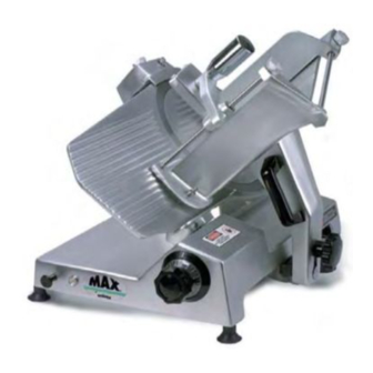
Page 3: Figure 1 Overall View Of Meat Slicer
9512 OVERALL VIEW OF MEAT SLICER Figure 1 1 INDICATOR LIGHT LAST SLICE DEVICE 2 ON-OFF SWITCH CARRIAGE ARM 3 FENCE 10 ELECTRIC CORD 4 KNIFE SHARPENER 11 CARRIAGE ARM KNOB 5 KNIFE GUARD 12 PROTECTIVE GUARD 6 CARRIAGE 13 GRADUATED KNOB... -
Page 4: Introduction
For SAFETY, follow the cleaning instructions on Page 6. INSTALLATION The most efficient installation of your Univex slicer will depend upon the layout of your kitchen. Locate your slicer where it will save steps for the operator and be sure to provide sufficient clearance around it for ease of maintenance and cleaning, as well as for efficient and safe use. -
Page 5: Operating Instructions
9512 OPERATION INSTRUCTIONS The Univex slicer is designed to meet the cook's demand for an efficient, sturdy slicer. The Univex slicer will give unfailing performance over a period of years, when operated and maintained according to instructions contained herein. START/STOP SWITCH The slicer is started by pulling the ON/OFF switch (Figure 1 [2]) out to the ON position. -
Page 6: Sharpening Instructions
9512 SHARPENING INSTRUCTIONS This slicer is equipped with a knife having a concave or hollowed surface for superior slicing quality. Of course, any knife, however superior, must be sharpened regularly and properly in order to produce not only the highest quality slices, but also to allow it to maintain its productivity. -
Page 7: Operator's Care Of Slicer - Cleaning Instructions
9512 OPERATORS CARE OF SLICER CLEANING Warning: Never touch the knife edge. Always keep your hands, fingers and arms clear of knife. Warning: Turn off slicer and DISCONNECT ELECTRICAL CORD (Figure 1 [10]) before cleaning. Leave protective guard (Fig. 2 [7]) in place. -
Page 8: Lubrication Instructions
9512 LUBRICATION A FUNCTION CHECK Warning: Turn off slicer and DISCONNECT ELECTRICAL CORD (Figure 1 [10]) before lubricating. Leave protective guard (Fig. 1 [12]) in place. General lubrication should be performed in accordance with the lubrication instructions below. During this lubrication sequence, be sure to check for free operation and movement of related parts as well as for excessive wear and looseness of various parts. -
Page 9: Troubleshooting Guide
9512 TROUBLESHOOTING GUIDE TROUBLE POSSIBLE CAUSE REMEDY 1. Slicer will not 1.1 Electrical service down. 1.1 Check electrical service. operate. Replace fuse or reset circuit breaker as necessary. 1.2 Burned switch contacts. 1.2 Clean or replace. 1.3 Motor capacitor defective. -
Page 10: Repair Instructions Including Disassembly, Replacement And Reassembly
9512 (including disassembly, replacement and reassembly) KNIFE (Removal) (Figure 2) 1. Warning Disconnect electrical power cord. 2. Remove carriage assembly (Fig. 5). 3. Remove knife guard knob (Fig. 2 [46]) and carefully remove knife guard. 4. Loosen sharpener lock pin (Fig. 6 [27]), lift and relock in up position. - Page 11 9512 Push knife support assembly from bottom and remove. 2. GEAR REPLACEMENT With knife support assembly removed, check gear (Fig. 2 [13]) for wear. If worn, replace. Remove snap ring (Fig. 2 [12]). Pry gear off of shaft. Replace gear in reverse procedures.
- Page 12 9512 ELECTRICAL ASSEMBLY Warning DISCONNECT ELECTRICAL SUPPLY Remove two legs (Fig. 2 [40]). Remove two leg brackets (Fig 2 [38]) Remove two screws (Fig. 3 [9]). Remove bottom cover (fig. 2 [42]). Replace two screws (Fig 3 [9]) securing square bar temporarily.
-
Page 13: Replacement Parts
9512 CASTING and BLADE ASSEMBLY Figure 2 ILLUS. NO. PART NO. DESCRIPTION QTY. 8512736 CASTING 8512203 8512851 STUD 8512852 NUT, ACONE M6-1.0 9512105 COVER, MOTOR 8512859 VENT 8512734 PROTECTIVE GUARD 8512215 SEAL 8512216 SEAL, O-RING 8512229 SCREW, FLAT HD M5-0.8 X 12MM... - Page 14 9512 CASTING and BLADE ASSEMBLY Figure 2 Page 13...
-
Page 15: Figure 3 Arm Assembly
9512 ARM ASSEMBLE Figure 3 ILLUS.NO. PART NO. DESCRIPTION QTY. 7510038 RUBBER SHOCK ABSORBER 8512314 SPRING, DAMPER 8512313 SCREW, SOC HD CAP M8-1.25 X 30MM 8512312 ROD, ROUND GUIDE 8512301 BUSHING 9512300 ARM BUSHING 8512316 BAR, FRAME 8512318 WASHER, EXTERNAL TOOTH... -
Page 16: Figure 4 Slice Control Assembly
9512 SLICE CONTROL ASSEMBLY Figure 4 ILLUS.NO. PART NO. DESCRIPTION QTY. 7510067 BOLT, SOC HD CAP M6-1.0 X 20MM 8512527 BOLT, HEX HD M8-1.25 X 30MM 8512526 8512525 WASHER, EXTERNAL TOOTH M6 7510065 SCREW, HEX HD M6-1.0 X 20MM 7512076... -
Page 17: Figure 5 Carriage Assembly
9512 CARRIAGE ASSEMBLY Figure 5 ILLUS NO. PART NO. DESCRIPTION QTY. 8512432 SPACER, ADJUSTMENT 8512437 STUD & KNOB, ADJUSTMENT SPACER RESERVED 8512433 BUSHING, ADJUSTMENT SPACER 8512925 SUPPORT, LAST SLICE DEVICE 8512924 HANDLE, LAST SLICE DEVICE 8512926 LAST SLICE DEVICE 6509153... -
Page 18: Figure 6 Sharpener Assembly
9512 SHARPENER ASSEMBLY Figure 6 ILLUS NO. PART NO. DESCRIPTION QTY. 7510151 SHARPENER ASSEMBLY WITH CONER 6509153 KNOB, COVER 6509151 COVER, SHARPENER 6509150 NUT, COVER SPACER 6509149 SPACER. COVER 6509125 WASHER, SET PIN 6509137 SCREW 6509138 WASHER 7510120 SET PIN, SHARPENER... -
Page 19: Figure 7 Electrical Assembly
9512 ELECTRICAL ASSEMBLY 115V, 60HZ, 1PH 100V, 50/60HZ, 1PH 220V,50HZz,1PH Figure 7 ILLUS. NO. PART NO. DESCRIPTION QTY. 85 12844 MOTOR, 115V, 60HZ, 1PH, 1/2HP, 100V, 50/60HZ, 1PH 8512844A MOTOR, 220V, 50HZ, 1PH, 1/2HP 8512601 8512602 RUBBER SHOCK ABSORBER 8512603... - Page 20 9512 ELECTRICAL ASSEMBLY Figure 7 Page 19...
-
Page 21: Figure 8 Schematic 115V, 60Hz, 1Ph, 100V, 50-60Hz, 1Ph
9512 SCHEMATIC 115V, 60HZ, 1PH, 100V, 50/60HZ, 1PH Figure 8 IMPORTANT: Before making electrical connections, check the specifications on the data plate to assure they agree with those of your electrical service. Whenever maintenance is being performed DISCONNECT electrical cord. -
Page 22: Figure 9 Schematic 220V, 50Hz, 1Ph, 100V, 50-60Hz, 1Ph
9512 SCHEMATIC 220V, 50HZ, 1PH FIGURE 9 Before making electrical connections, check the specifications on the data plate IMPORTANT: to assure they agree with those of your electrical service. Whenever maintenance is being performed DISCONNECT electrical cord. WARNING: Page 21...
Need help?
Do you have a question about the 9512 and is the answer not in the manual?
Questions and answers