
Related Manuals for Univex 6509


Summary of Contents for Univex 6509
- Page 1 INSTRUCTION 6509 SLICER MANUAL WE THANK YOU FOR YOUR PURCHASE OF OUR MODEL 6509 SLICER. 65094910014/9208...
-
Page 2: Table Of Contents
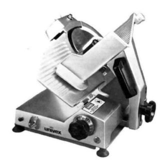
Warranty Information ....................……..Back Cover LIST OF ILLUSTRATIONS AND FIGURE DRAWINGS ILLUSTRATIONS PAGE Fig. 1 Overall View of Slicer Model 6509..............……... Fig. 2 Lubrication Diagram and Instruction ..............……... Fig. 3 Sharpener, Knife, Pulley, and Motor Assemblies ..........…….. 14 - 16 Fig. - Page 3 6509 OVERALL VIEW OF SLICER MODEL 6509 FIGURE 1 1 FENCE 8 GRADUATED KNOB 2 KNIFE SHARPENER 9 SERIAL NAME PLATE 3 KNIFE GUARD 10 ON-OFF SWITCH 4 LAST SLICE DEVICE 11 INDICATOR LIGHT 5 CARRIAGE ARM KNOB 12 CARRIAGE...
-
Page 4: Introduction
Lift slicer by handling the base. INSPECTION All Univex slicers are inspected and tested at the factory; however, they should be reinspected carefully by the person making the installation for loose, damaged or broken parts. Detached parts and fixtures should be checked against packing list to determine all are present. -
Page 5: Operating Instructions
6509 OPERATING INSTRUCTIONS The Univex slicer is designed to meet the cook's demand for an efficient, sturdy slicer. The Univex slicer will give unfailing performance over a period of years, when operated and maintained according to instructions contained herein. A high torque motor drives the knife through a highly efficient polyvee (multi-ribbed) belt and mating pulleys. The upper pulley. -
Page 6: Sharpening Instructions
6509 KNIFE GUARD Warning: The knife guard (Fig. 1 [3D covers the knife completely except the forward edge where slicing will be performed. This forward edge is covered by the edge of the fence, but only when the slice adjustment is completely closed. -
Page 7: Operator's Care Of Slicer - Cleaning Instructions
6509 Turn slicer OFF. Loosen lock pin, then lift and return sharpener to its storage position. Tighten lock pin. Clean slicer and knife according to the cleaning procedure on Page 7 in order to thoroughly remove grinding debris. OPERATORS CARE OF SLICER CLEANING Warning: Never touch the knife. -
Page 8: Mechanics Maintenance
6509 LUBRICATION Lubrication instructions are given in Figures 2 and 2A on pages 10 and 11. Operator's attention is called to lubricating the slide bar (Fig. 4 [52]) as needed for smooth carriage motion, at least monthly with three drops of mineral oil. - Page 9 6509 sequence, be sure to check for free operation and movement of related parts as well as for excessive wear and looseness of various parts. Be sure to check all handles and knobs for tightness. KNIFE - Check knife edge to see that it has been properly sharpened. If there is any evidence of incorrect sharpening procedure, such as excessive honing, alert owner and operator.
-
Page 10: Lubrication Instructions
6509 LUBRICATION INSTRUCTIONS MODEL 6509 FIGURE 2 A - Petrogel, often as required to maintain light film. B - Oil monthly, three drops mineral oil. PAGE 9... -
Page 11: Trouble Shooting Guide
6509 TROUBLESHOOTING GUIDE 6509 TROUBLE POSSIBLE CAUSE REMEDY 1. Slicer will not operate. 1.1 Electrical service down. 1.1 Check electrical service. Replace fuse or reset circuit breaker as necessary. 1.2 Burned switch contacts. 1.2 Replace switch. 1.3 Motor capacitor defective. -
Page 12: Repair Instructions Including Disassembly, Replacement, And Reassembly
6509 REPAIR INSTRUCTIONS Including disassembly, replacement and reassembly. Warning: Always turn off slicer and disconnect electrical cord before doing any maintenance or repair of the slicer. Keep guards on at all times. Keep slice adjustment fully closed so knife edge is not exposed. Keep sharpener assembly also in place so top of knife edge is not exposed. - Page 13 6509 KNIFE REPLACEMENT 1. Disconnect electrical power cord. 2. Loosen sharpener lock pin (Fig. 3 [4]), then lift and remove sharpening unit. Set aside. 3. Remove knife guard knob (Fig. 3 [64]) and carefully remove knife guard (Fig. 3 [40]).
- Page 14 6509 11. Reinstall knife, knife guard and sharpener in the reverse procedure outlined above. SHARPENING STONES Disconnect electrical cord. 2. Unscrew sharpener lock pin (Fig. 3 [4])- 3. Lift up sharpening assembly (Fig. 1 [2]) and remove from slicer. 4. Using an open end wrench, unscrew cover knob (Fig. 3 [23]). It is recommended that a piece of tape or paper be temporarily wrapped around knob prior to unscrewing it so as to protect its finish.
-
Page 15: Replacement Parts Lists Keyed To Figure Drawings
6509141 STUD, .LOWER STONE 6509142 STONE, LOWER 6509144 WASHER, M6 FLAT 6509143 NUT, M6-1.0 HEX 6509 35 BUTTON. STONE DEPRESS 6509 36 SCREW, M3-0.5 X 5 OVAL HD SLOTTED 6509 34 SPRING. DEPRESS BUTTON 6509 33 BALL BEARING 6509 31 NUT. - Page 16 6509 SHARPENER, KNIFE, PULLEY AND MOTOR ASSEMBLIES FIGURE 3 (CONT) ILLUS. NO. PART NO. DESCRIPTION QTY. 6509020 SCREW, M3-0.5 X 8 FLAT HD PHIL 6509019 GUARD, BELT 6509155 BELT 6509005 SET SCREW, M8-1.25 X 10 CUP POINT 6509103 COLLAR, MOTOR ADJ.
- Page 17 6509 SHARPENER, KNIFE, PULLEY AND MOTOR ASSEMBLIES FIGURE 3 PAGE 16...
- Page 18 6509 FENCE, FENCE ADJUST, CARRIAGE, CARRIAGE ARM CARRIAGE ARM SUPPORT AND FEED GRIP ASSEMBLY FIGURE 4 ILLUS. NO. PART NO. DESCRIPTION QTY. FENCE MOUNTING BRACKET AND SHAFT ASSEMBLY INCLUDES NO. 1 THRU 3 6509076 SHAFT, FENCE ARM 6509077 BRACKET, FENCE MOUNTING 6509083 SET SCREW, M6-1.0 X 12 CUP POINT...
- Page 19 6509 FENCE, FENCE ADJUST, CARRIAGE, CARRIAGE ARM CARRIAGE ARM SUPPORT AND FEED GRIP ASSEMBLY FIGURE 4 (CONT) ILLUS. NO. PART NO. DESCRIPTION QTY. 6509064 SUPPORT, FENCE ADJ 6509073 SET SCREW, M6-1 0 X 20 FLAT POINT 6509074 NUT, M6-1 0 HEX...
- Page 20 6509 FENCE, FENCE ADJUST, CARRIAGE, CARRIAGE ARM CARRIAGE ARM SUPPORT AND FEED GRIP ASSEMBLY FIGURE 4 PAGE 19...
- Page 21 6509 CAPACITOR PANEL 220-240V, 50/60HZ, 1PH FIGURE 4A ILLUS. NO. PART NO. DESCRIPTION QTY. 7120017 NUT, HEX M5-0.8 1200076 WASHER, FLAT NO. 10 NOT USED 4400224 BRACKET, CAPACITOR 220-240V 7120051 CAPACITOR, 5MFD 6509113 STUD, M5-0.8 X 25MM 7120008 BOOT, CAPACITOR...
- Page 22 6509 CAPACITOR PANEL 100V, 50/60HZ, 1PH FIGURE 4B ILLUS. NO. PART NO. DESCRIPTION QTY. 7120017 NUT, M5-0.8 1200076 WASHER , FLAT NO. 10 4400101 CLAMP, CABLE 4400024 BRACKET, CAPACITOR 7120001 CAPACITOR, 20MFD, 370V, 50/60HZ, 115V 6509113 STUD, M5-0.8 X 25MM...
- Page 23 FEET, RUBBER SUCTION 7120128 SPACER, LEG, (100V ONLY) 7120129 STUD, LEG, M6-1.0 X 20MM, (100V ONLY) 7120011 GUARD, SWITCH 4400081 PIN, SWITCH GUARD 1024010 LABEL, UNIVEX (NOT SHOWN) 4400113 LABEL, STOP-UNPLUG (NOT SHOWN) 4400409 LABEL, DANGER (NOT SHOWN) PAGE 22...
-
Page 24: Wiring Diagram
6509 WIRING DIAGRAM MODEL 6509, 115V, 50/60HZ, 1PH FIGURE 6 IMPORTANT Warning: Before making electrical connections, check the specifications on the data plate to assure they agree with those of your electrical service. Whenever cleaning or maintenance is being performed, DISCONNECT electrical cord. -
Page 25: Fig 6A Wiring Diagram 220-240V, 50/60Hz, 1Ph
6509 WIRING DIAGRAM MODEL 6509, 220-240V, 50/60HZ, 1PH FIGURE 6A IMPORTANT Warning: Before making electrical connections, check the specifications on the data plate to assure they agree with those of your electrical service. Whenever cleaning or maintenance is being performed, DISCONNECT electrical cord. -
Page 26: Fog. 6B Wiring Diagram 100V. 50/60Hz. 1Ph
6509 WIRING DIAGRAM MODEL 6509, 100V, 50/60HZ, 1PH FIGURE 6B * CAUTION: Installations with 50HZ electrical supplies should have black motor lead connected to 110V output terminal ONLY. Connection to higher voltage outputs could cause motor failure. The transformer has been wired at the factory for 50HZ operation at 110V output.
Need help?
Do you have a question about the 6509 and is the answer not in the manual?
Questions and answers