
Subscribe to Our Youtube Channel
Related Manuals for Univex PREP SAVER 6512 SERIES


Summary of Contents for Univex PREP SAVER 6512 SERIES
- Page 1 INSTRUCTION 6512 PREP SAVER Slicer MANUAL SERIES WE THANK YOU FOR YOUR PURCHASE OF OUR MODEL 6512 SLICER. 6512/9812...
-
Page 2: Table Of Contents
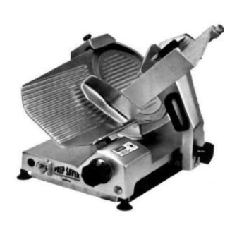
6512 TABLE OF CONTENTS DESCRIPTION PAGE Table of Contents List of Illustrations Introduction Installation Instruction Safety Warnings Operating Instructions Sharpening Instructions Operator's Care of Slicer - Cleaning & Lubrication Mechanic's Maintenance Trouble Shooting Guide Repair Instructions including Disassembly, Replacement, and Reassembly 10- 12 Replacement Parts Lists Keyed to Figure Drawings 13- 19... - Page 3 6512 OVERALL VIEW OF MEAT SLICER MODEL 6512 FIGURE 1 1 FENCE 8 CARRIAGE ARM 2 KNIFE SHARPENER 9 GRADUATED KNOB 3 KNIFE GUARD 10 ON-OFF SWITCH 4 PROTECTIVE GUARD 11 INDICATOR LIGHT 5 LAST SLICE DEVICE 12 CARRIAGE 6 ELECTRIC CORD (NOT SHOWN) 13 SERIAL NAME PLATE (NOT SHOWN) 7 CARRIAGE ARM KNOB...
-
Page 4: Introduction
For SAFETY, follow the cleaning instructions on Page 5. INSTALLATION The most efficient installation of your Univex slicer will depend upon the layout of your kitchen. Locate your slicer where it will save steps for the operator and be sure to provide sufficient clearance around it for ease of maintenance and cleaning, as well as for efficient and safe use. -
Page 5: Operating Instructions
6512 OPERATION INSTRUCTIONS The Univex slicer is designed to meet the cook's demand for an efficient, sturdy slicer. The Univex slicer will give unfailing performance over a period of years, when operated and maintained according to instructions contained herein. START/STOP SWITCH The slicer is started by toggling the ON/OFF switch (Figure 1 [10]) to the ON position. -
Page 6: Operator's Care Of Slicer - Cleaning & Lubrication
6512 The knife cutting area should be clean and free from food, especially grease. Grease will ruin the ability of a grinding stone to sharpen an edge. The stone simply will not cut. If cleaning is necessary, follow the procedure outlined on Page 5. Loosen sharpener knob assembly (Figure 5 [28]) which bears against sharpener post, then lift sharpener assembly (Figure 1 [2]) and rotate it 1/2 turn (180°). - Page 7 6512 Never use detergents or wash the slicer or any of its parts in a dishwashing machine or the clear protective finish will be damaged. Warning 5. Wash body of slicer using warm water and mild soap using a clean soft cloth.
- Page 8 6512 LUBRICATION FIGURE 2 A - Apply Petro-Gel (4400408) often as required to maintain light film. B - Clean and apply mineral oil weekly. Page7...
-
Page 9: Mechanics Maintenance
6512 MECHANICS MAINTENANCE Every year a mechanic or service technician should perform the following inspection and carry out the respective maintenance as required: Warning: FOR SAFETY, TURN OFF SLICER AND DISCONNECT ELECTRICAL CORD. 1. BELT DRIVE - This drive features a multi-ribbed high performance belt for long trouble-free service. -
Page 10: Trouble Shooting Guide
6512 TROUBLESHOOTING GUIDE 6512 TROUBLE POSSIBLE CAUSE REMEDY 1. Slicer will not operate. 1.1 Electrical service down. 1.1 Check electrical service. Replace fuse or reset circuit breaker as 1.2 Burned switch contacts. necessary. 1.3 Motor capacitor defective. 1.2 Replace switch. 1.4 Burned out motor. -
Page 11: Repair Instructions Including Disassembly, Replacement, And Reassembly
6512 REPAIR INSTRUCTIONS Including disassembly, replacement, and reassembly. Warning: Always turn off slicer and disconnect electrical cord before doing any maintenance or repair on the slicer. Keep guards on at all times. Keep slice adjustment fully closed so knife edge is not exposed. Keep sharpener assembly also in place so top of knife edge is not exposed. - Page 12 6512 Reinstall pulley insert and shims that may have been present. Apply liberal coating of Petro-Gel to the seal/insert interface. Reinstall knife, knife guard and sharpener in the reverse procedure outlined above. SHARPENING STONES Warning: Disconnect electrical cord. Unscrew sharpener knob assembly (Figure 5 [28]). Lift up sharpening assembly (Figure 1 [2] ) and remove from slicer.
- Page 13 6512 Install replacement belt on knife pulley and on motor pulley shaft. DO NOT reinstall knife at this time. Reinstall motor pivot bolt. Reinstall spring and nuts on motor adjustment rod (Figure 3 [26] ) and tighten. It is important to make sure that the belt is aligned on both pulleys. Belt tension is correct wh en the spring is compressed to an overall length of 7/8".
-
Page 14: Replacement Parts Lists Keyed To Figure Drawings
6512 KNIFE, PULLEY AND MOTOR ASSEMBLIES FIGURE 3 ILLUS. NO. PART NO. DESCRIPTION QTY. 6512020 HOUSING, TOP PULLEY ASSEMBLY INCLUDES NO. 2 THRU 8 6512021 SHAFT, PULLEY 6512043 SNAP RING, PULLEY 6512022 SPACER, PULLEY 6512044 BEARING, PULLEY 6512023 PULLEY 6512045 SEAL, PULLEY 6512024 INSERT, PULLEY... - Page 15 6512 KNIFE, PULLEY AND MOTOR ASSEMBLY FIGURE 3 Page 14...
- Page 16 6512 FENCE, FENCE ADJUST, CARRIAGE, CARRIAGE ARM CARRIAGE ARM SUPPORT AND FEED GRIP ASSEMBLY FIGURE 4 ILLUS. NO. PART NO. DESCRIPTION QTY. FENCE MOUNTING BRACKET AND SHAFT ASSEMBLY INCLUDES NO. 1 THRU 3 6509076 SHAFT, FENCE ARM 6512031 BRACKET, FENCE MOUNTING 6509083 SET SCREW, M6-1.0 X 12 CUP POINT 6509081...
- Page 17 6512 FENCE, FENCE ADJUST, CARRIAGE, CARRIAGE ARM CARRIAGE ARM SUPPORT AND FEED GRIP ASSEMBLY FIGURE 4 (CONT) ILLUS. NO. PART NO. DESCRIPTION QTY. 6509073 SET SCREW, M6-1.0 X 20 FLAT POINT 6509074 NUT, M6-1.0 HEX 6509067 SCREW, M6-1.0 X 18 HEX SOCKET HD 6509072 NUT, M8-1.25 HEX 6509070...
- Page 18 6512 FENCE, FENCE ADJUST, CARRIAGE, CARRIAGE ARM CARRIAGE ARM SUPPORT AND FEED GRIP ASSEMBLY FIGURE 4 Page 17...
- Page 19 6512 SHARPENER ASSEMBLY FIGURE 5 ILLUS. NO. PART NO. DESCRIPTION 6509153 KNOB 6512054 COVER 6509150 6509149 SPACER 6509137 SCREW 8512728 STUD MOUNTING 6509125 WASHER, SET PIN 7510120 PIN, SET 6509127 SPRING 6509128 BUSHING 6509129 STUD, HONING 6509130 STONE, HONING 6509131 6509134 SPRING 6509133...
- Page 20 SET SCREW, M6-1.0 X 14, CUP POINT 7120009 SWITCH, 115V, 220-240V 6512042 COVER, BOTTOM 6509093 FEET, RUBBER SUCTION 7120011 GUARD, SWITCH 4400081 PIN, SWITCH GUARD 4400337 LABEL, UNIVEX PREP-SAVER (NOT SHOWN) 4400409 LABEL, DANGER (NOT SHOWN) CANADA ONLY 4400236 CIRCUIT BREAKER 4400227 LABEL, RESET Page 19...
-
Page 21: Wiring Diagram
6512 WIRING DIAGRAM MODEL 6512 115V, 60HZ, 1PH, 230V, 50/60HZ, 1PH FIGURE 7 IMPORTANT Warning: Before making electrical connections, check the specifications on the data plate to assure they agree with those of your electrical service. Whenever cleaning or maintenance is being performed, DISCONNECT electrical cord. Page 20...
Need help?
Do you have a question about the PREP SAVER 6512 SERIES and is the answer not in the manual?
Questions and answers