Univex duro 7510 Instruction Manual
Hide thumbs
Also See for duro 7510:
- Operator's manual (11 pages) ,
- Instruction manual (32 pages) ,
- Instruction manual (19 pages)

Related Manuals for Univex duro 7510


Summary of Contents for Univex duro 7510
- Page 1 INSTRUCTION 7510,7512 DURO Slicer MANUAL SERIES WE THANK YOU FOR YOUR PURCHASE OF OUR MODEL 7510, 7512 SLICER. 1948 SINCE 7510/12/1099...
-
Page 2: Table Of Contents
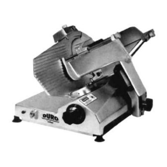
7510/7512 TABLE OF CONTENTS DESCRIPTION PAGE Table of Contents List of Illustrations Introduction Installation Instructions Important Safety Warnings Operating Instructions Sharpening Instructions Operator's Care of Slicer / Lubrication Trouble Shooting Chart Mechanics Maintenance Repair, incl. Disassembly, Replacement and Reassembly 10-12 Replacement of Parts, List 13-26 Warranty... - Page 3 7510/7512 OVERALL VIEW OF MEAT SLICER MODEL 7510 - 7512 FIGURE 1 1 ON-OFF SWITCH ADJUSTMENT SPACER 2 INDICATOR LIGHT ELECTRIC CORD 3 CARRIAGE 10 CARRIAGE ARM KNOB 4 FENCE 11 CARRIAGE ARM 5 LAST SLICE DEVICE 12 REMOVABLE CHEESE SCRAPER 6 KNIFE SHARPENER 13 GRADUATED KNOB 7 KNIFE GUARD...
-
Page 4: Introduction
Detached parts and fixtures should be checked against packing list to determine all are present. Any damages should be reported to t he Carrier immediately, and any shortages of parts or fixtures reported to Univex Corporation. -
Page 5: Operating Instructions
7510/7512 OPERATION INSTRUCTIONS The Univex slicer is designed to meet the Cook's demand for an efficient, sturdy slicer. The Univex slicer will give unfailing performance over a period of years, when operated and maintained according to instructions contained herein. START/STOP SWITCH The slicer is started by pushing the start/stop toggle switch (Figure 1 [ 1 ]) upward to the ON position. -
Page 6: Operator's Care Of Slicer / Lubrication
7510/7512 necessary, follow the procedure outlined on Page 5-6. Remember to unplug the electrical supply cord. Loosen sharpener lock pin (Figure 3 [4]) which bears against sharpener post, then lift sharpener assembly (Figure 1 [6]) and rotate it 1/2 turn (180 degrees). Then seat it down over knife. Tighten sharpener lock pin (Figure 3 [4]). - Page 7 7510/7512 WARNING: 5. Wash body of slicer using warm water and mild soap using a soft cloth. Under no circumstances should the slicer be hose rinsed. It is recommended that the cloth be folded over a thin wooden stick when cleaning between the fence plate and the knife.
- Page 8 7510/7512 LUBRICATION INSTRUCTIONS MODEL 7510 - 7512 FIGURE 2 A PETROGEL, AS REQUIRED TO MAINTAIN B OIL MONTHLY, THREE DROPS LIGHT FILM, MINERAL OIL. PAGE 7...
-
Page 9: Trouble Shooting Chart
7510/7512 TROUBLESHOOTING GUIDE 7510/7512 TROUBLE POSSIBLE CAUSE REMEDY 1. Slicer will not 1.1 Electrical service down. 1.1 Check electrical service. operate. Replace fuse or reset circuit 1.2 Burned switch contacts. breaker as necessary. 1.3 Motor capacitor defective. 1.2 clean or replace. 1.4 burned out motor 1.3 replace. -
Page 10: Mechanics Maintenance
7510/7512 MECHANIC'S MAINTENANCE Every year a mechanic or service technician should perform the following inspection and carry out the respective maintenance as required: FOR SAFETY, TURN OFF SLICER AND DISCONNECT ELECTRICAL CORD. 1. BELT DRIVE: This d rive features a multi-ribbed high performance belt for long trouble-free service. Inspect belt for proper tension. -
Page 11: Repair, Incl. Disassembly, Replacement And Reassembly
7510/7512 REPAIR INSTRUCTIONS (including disassembly, replacement and reassembly.) Always turn off slicer and disconnect electrical cord before doing any maintenance or repair on the slicer. Keep guards on all times. Keep slice adjustment fully closed so knife edge is not exposed. Keep sharpener assembly also in place so top of knife edge is not exposed. - Page 12 7510/7512 KNIFE (Removal Figure 3) Disconnect electrical power cord. Loosen sharpener lock pin (Figure 3 [4]), then lift and remove sharpening unit. Set aside. Remove knife guard knob (Figure 3 [2]) and carefully remove knife guard (Figure 3 [14]). Using caution to avoid the sharp knife edge, remove the four screws (Figure 3 [12]) that secure knife (Figure 3 [15]).
-
Page 13: Replacement Of Parts, List
7510/7512 SHARPENING STONES Disconnect electrical cord. Unscrew sharpener lock pin (Figure 3 [4]). Lift up sharpening assembly (Figure 1 [6]) and remove from slicer. Using an open end wrench, unscrew cover knob (Figure 4 [1]). It is recommended that a piece of tape or paper be temporarily wrapped around knob prior to unscrewing it so as to protect its finish. - Page 14 7510/7512 BASE AND KNIFE HOUSING ASSEMBLY MODEL 7510 - 7512 FIGURE 3 ILLUS. NO. PART NO. DESCRIPTION QTY. 7510012 WASHER, KNIFE 7510015 KNOB, KNIFE GUARD 7510013 NUT KNIFE 7510150 LOCK PIN, SHARPENER 7510001 BACK KNIFE GUARD (MODEL 7510) 7512001 BACK KNIFE GUARD (MODEL 7512) 7510156 WASHER, KNIFE SHIM AS REQ;...
- Page 15 7510/7512 BASE AND KNIFE HOUSING ASSEMBLY MODEL 7510 - 7512 FIGURE 3 PAGE 14...
- Page 16 7510/7512 SHARPENER ASSEMBLY MODEL 7510 - 7512 FIGURE 4 ILLUS NO. PART NO. DESCRIPTION QTY. 7510151A SHARPENER ASSEMBLY WITH CONER 6509153 KNOB, COVER 6509151 COVER, SHARPENER 6509150 NUT, COVER SPACER 6509149 SPACER. COVER 6509125 WASHER, SET PIN 6509137 SCREW RESERVED 7510120 SET PIN, SHARPENER 8512728...
- Page 17 7510/7512 CARRIAGE ASSEMBLY MODEL 7510 FIGURE 5 ILLUS. NO. PART NO. DESCRIPTION QTY. 8512432 SPACER, ADJUSTMENT 8512436 STUD, ADJUSTMENT SPACER 6509153 KNOB 8512433* BUSHING ADJUSTMENT SPACER 8512426 LAST SLICE DEVICE 6509054 KNOB, LAST SLICE DEVICE 8512428 SHAFT, LAST SLICE DEVICE 8512427** BUSHING, LAST SLICE DEVICE 8512425...
- Page 18 7510/7512 CARRIAGE ASSEMBLY MODEL 7512 FIGURE 5A ILLUS. NO. PART NO. DESCRIPTION QTY. 8512432 SPACER, ADJUSTMENT 8512436 STUD, ADJUSTMENT SPACER 6509153 KNOB 8512433* BUSHING ADJUSTMENT SPACER 8512925 SUPPORT, LAST SLICE DEVICE 8512924 KNOB, LAST SLICE DEVICE 8512926 LAST SLICE DEVICE 8512428 SHAFT, LAST SLICE DEVICE 8512427**...
- Page 19 7510/7512 CARRIAGE ARM AND SLIDE ASSEMBLY MODEL 7510 - 7512 FIGURE 6 ILLUS. NO. PART NO. DESCRIPTION QTY. 6509036 WASHER, SLIDE BAR RUBBER 7510337. SPRING, SLIDE BAR (7512 ONLY) 6509035 SPRING, SLIDE BAR (7510 ONLY) 8512229 SCREW, M5-0.8 X 12MM FL HD SLT 7510434 BAR, CARRIAGE SLIDE 7510326**...
- Page 20 7510/7512 SLICE ADJUSTMENT ASSEMBLY MODEL 7510 - 7512 FIGURE 7 ILLUS. NO. PART NO. DESCRIPTION QTY. 7510067 SCREW, SLICE CONTROL ATTACHMENT 8512527 SCREW, SLICE CONTROL ATTACHMENT 8512526 8512525 WASHER, TOOTHED 7510065 SCREW, JIB ATTACHMENT 7512076 BOLT, TAPER SUPPORT (7512 ONLY) 7510076 BOLT, TAPER SUPPORT (7510 ONLY) 8512839...
- Page 21 7510/7512 FENCE ASSEMBLY MODEL 7510 - 7512 FIGURE 8 ILLUS. NO PART NO. DESCRIPTION QTY. 7510079 FENCE (MODEL 7510) 7512079 FENCE (MODEL 7512) SHIMS AS REQ 1200300 ROLL PIN 3/16 X 2 7510077 BRACKET, FENCE MOUNTING (MODEL 7510) 7512077 BRACKET, FENCE MOUNTING (MODEL 7512) 8512326 SET SCREW 6509081...
- Page 22 7510/7512 MOTOR. MOUNT AND DRIVE ASSEMBLY MODEL 7510 - 7512 (115V, 50/60HZ, 1PH) (100V, 50/60HZ, 1PH) FIGURE 9 ILLUS. NO. PART NO. DESCRIPTION QTY. 6090000 MOTOR, 1/3 HP, 115V, 50/60HZ, 1PH 4400085 TUBING, CORD 15 FT 1200076 WASHER NO. 10 7120034 BRACKET, LEFT 4400183...
- Page 23 7510/7512 MOTOR. MOUNT AND DRIVE ASSEMBLY MODEL 7510 - 7512 (115V, 50/60HZ, 1PH) (100V, 50/60HZ, 1PH) FIGURE 9 PAGE 22...
- Page 24 7510/7512 TRANSFORMER / CAPACITOR PANEL 100V,50/60HZ,1PH FIGURE 9A ILLUS. NO. PART NO. DESCRIPTION 1200076 WASHER, NO. 10 4400191 WASHER, RUBBER 4400065 WASHER, LOCK NO. 10 7120017 NUT, M5-0.8 4400101 CLAMP, CABLE 4400053 CORD, ELECTRICAL 1212042 STRAIN, RELIEF 7120001 CAPACITOR, 20MFD, 370V, 50/60HZ, 115V 4400024 BRACKET, CAPACITOR 7120008...
- Page 25 7510/7512 MOTOR. MOUNT AND DRIVE ASSEMBLY MODEL 7510 - 7512 220-240V, 50/60HZ, 1PH FIGURE 10 ILLUS. NO. PART NO. DESCRIPTION QTY. 6090002 MOTOR 1/3HP, 220-240V, 50/60HZ, 1PH 4400085 TUBING, CORD 1.5FT 1200076 WASHER NO. 10 7120034 BRACKET, LEFT 4400183 LOCKWASHER NO. 8 1200058 NUT 8-32 7510099...
- Page 26 7510/7512 MOTOR. MOUNT AND DRIVE ASSEMBLY MODEL 7510 - 7512 220-240V, 50/60HZ, 1PH Figure 10 PAGE 25...
- Page 27 7510/7512 CAPACITOR PANEL 220- 240V, 50/60HZ, 1PH Figure. 10A ILLUS. NO. PART NO. DESCRIPTION QTY. 7120052 PANEL, CAPACITOR 1200076 WASHER, FLAT NO. 10 1200415 SCREW, HEX HD 10-32 X 1 1/4 6509113 STUD, M5-0.8 X 40MM 1200430 WASHER, LOCK N0.6 1200429 NUT, HEX 6-32 1814062...
- Page 28 7510/7512 WIRING DIAGRAM MODEL 7510 - 7512 115V, 50/60 HZ, 1PH FIGURE 11 IMPORTANT Before making electrical connections, check the specifications on the data plate to assure they agree with those of your electrical service. Whenever cleaning or maintenance is being performed DISCONNECT electrical cord. PAGE 27...
- Page 29 7510/7512 WIRING DIAGRAM MODEL 7510 - 7512 220-240V, 50/60HZ, 1PH FIGURE 11A IMPORTANT Before making electrical connections, check the specifications on the data plate to assure they agree with those of your electrical service. Whenever cleaning or maintenance is being performed DISCONNECT electrical cord. PAGE 28...
- Page 30 7510/7512 WIRING DIAGRAM MODEL 7510 - 7512 100V, 50/60HZ, 1PH FIGURE 11B * CAUTION: Installations with 50HZ electrical supplies should have black motor lead connected to 110V output terminal ONLY. Connection to higher voltage outputs could cause motor failure. The transformer has been wired at the factory for 50HZ operation at 110V output.
Need help?
Do you have a question about the duro 7510 and is the answer not in the manual?
Questions and answers