
Subscribe to Our Youtube Channel
Related Manuals for Ruijie RG-AP820(AR)


Summary of Contents for Ruijie RG-AP820(AR)
- Page 1 Ruijie RG-AP820(AR) Access Point Hardware Installation and Reference Guide Document Version: V1.0 Date: 2022.02.11 Copyright © 2022 Ruijie Networks...
- Page 2 All rights are reserved in this document and this statement. Any reproduction, excerption, backup, modification, transmission, translation or commercial use of this document or any portion of this document, in any form or by any means, without the prior written consent of Ruijie Networks is prohibited.
- Page 3 Preface Intended Audience This document is intended for: Network engineers Technical support and servicing engineers Network administrators Technical Support Ruijie Networks Website: https://www.ruijienetworks.com/ Technical Support Website: https://ruijienetworks.com/support Case Portal: https://caseportal.ruijienetworks.com Community: https://community.ruijienetworks.com ...
-
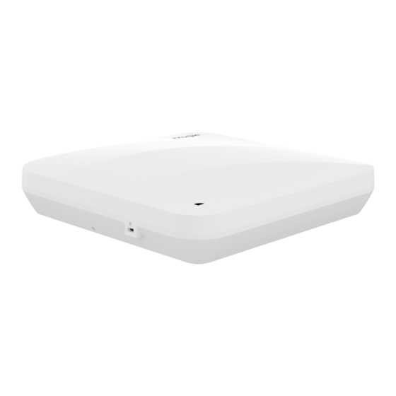
Page 4: Product Introduction
Internet of Things (IoT) module are fully taken into account for the RG- AP820(AR). Therefore, this AP can be used together with Ruijie's access controllers (ACs) and WIS to implement STA data forwarding, security, access control, and IoT application extension. - Page 5 PoE power supply.) LAN 3 port can be used as a downlink 1 Gbps copper port. Service Ports LAN 3 port allows the AP to power external devices (12 V/2 W). (The port can be connected to Ruijie's IoT module.) Management Port 1 console port USB Port USB 2.0 port...
- Page 6 1 Gbps copper port. LAN 1 port supports PoE/802.3at/802.3af power supply. LAN 3/IoT port can be connected to Ruijie's IoT module for power supply (12 V/0.25 A, MAX: 2 W). In addition, there are one console port, one power socket for an external power adapter, one USB port, and one reset hole. The following figures...
- Page 7 Hardware Installation and Reference Guide Product Introduction Description ① LED ⑥ LAN 3/IoT port ② Kensington Lock ⑦ LAN 2 port ③ USB port ⑧ LAN 1/PoE port ④ Reset button ⑨ Input port for the 48 V DC adapter ⑤...
- Page 8 The RG-AP820(AR) can be powered by a DC adapter or PoE+. Caution To power the RG-AP820(AR) by using a DC adapter, use an adapter with specifications recommended by Ruijie. (For details about the adapter specifications, see Section 2.2.5 and Appendix C.) To power the RG-AP820(AR) by using PoE+, ensure that the device at the other end of the Ethernet cable supports IEEE 802.3at power supply.
-
Page 9: Preparing For Installation
Hardware Installation and Reference Guide Preparing for Installation Preparing for Installation Safety Precautions Caution To avoid personal injury and device damage, carefully read the safety precautions before you install the AP. The following safety precautions may not cover all possible dangers. 2.1.1 General Safety Precautions ... -
Page 10: Installation Environment Requirements
Hardware Installation and Reference Guide Preparing for Installation Caution Improper or incorrect electric operations may cause a fire, electric shock, and other accidents, and lead to severe and fatal personal injury and device damage. Direct or indirect contact with high voltage or mains power supply through wet objects may cause fatal dangers. - Page 11 AP must be not less than 25.5 W. To power the AP by using a DC adapter, select an adapter with specifications recommended by Ruijie. (For details about the outer and inner diameters of the DC adapter, see Appendix C.) To power the AP by using a PoE injector, select a PoE injector certified by Ruijie.
-
Page 12: Unpacking The Ap
Hardware Installation and Reference Guide Preparing for Installation Caution The RG-AP820(AR) is delivered without a tool kit. The tool kit and cables are customer-supplied. Unpacking the AP Package Contents Check whether each panel of the device is properly assembled and whether the device is debugged. -
Page 13: Installing The Ap
Hardware Installation and Reference Guide Installing the AP Installing the AP The RG-AP820(AR) must be installed and secured indoors. Caution Ensure that you have read through Chapter 2 carefully and requirements in Chapter 2 are all met. Installation Procedure Before You Begin Carefully plan and arrange the installation location, networking mode, power supply, and cabling before installing the AP. - Page 14 Hardware Installation and Reference Guide Installing the AP Do not wipe the device with a damp cloth. Do not wash the device with liquid. Do not open the enclosure when the device is working. Fasten the device tightly. Installing the AP Caution You are advised to install the device where you can get the optimal coverage.
- Page 15 Hardware Installation and Reference Guide Installing the AP Caution Install the Ethernet cables before mounting the AP on the bracket. Step 3. Slide the AP onto the bracket in the opposite direction of the arrow on the mounting bracket until it clicks into place.
- Page 16 Hardware Installation and Reference Guide Installing the AP Caution The AP can be installed in any of four directions on the mounting bracket depending on how you route the Ethernet cable. The square feet should fit easily into the mounting holes. Do not forcibly push the AP into the holes. After installation, verify that the AP is securely fastened.
-
Page 17: Securing The Ap
Caution When mounting the AP on the wall, keep the Ruijie logo pointed upwards. The AP must be slid in the opposite direction of the arrow on the mounting bracket until it clicks into place. Do not forcibly push the AP into the holes. - Page 18 Step 1. If the security screw is used, keep the top of the security screw pin against the edge of the mounting bracket (with the Ruijie logo on the pin pointed upwards), slide the pin along the four directions, and try to insert the pin into the four security screw marks to find the target hole.
-
Page 19: Connecting Cables
Hardware Installation and Reference Guide Installing the AP Step 3. If the AP is installed on a ceiling, hold the AP in your hands and slide it sideways and away from the bracket in the LAN port direction. Figure 3-11 Removing a Ceiling-mounted AP Ceiling Push out Connecting Cables... -
Page 20: Bundling Cables
Hardware Installation and Reference Guide Installing the AP Caution By default, the baud rate is set to 9600, data bit to 8, stop bit to 1, with no parity check and no flow control on the console port of the AP. The console port is used only when you want to configure the AP manually. Avoid a small bend radius at the connector. -
Page 21: Setting Up The Configuration Environment
Hardware Installation and Reference Guide Verifying the Operating Status Verifying the Operating Status Setting Up the Configuration Environment Use a power adapter or PoE+ to power the AP. Setting up the Environment Verify that the AP is properly connected to the power source. ... -
Page 22: Monitoring And Maintenance
If the AP works in fat mode, you can log in to the AP remotely for maintenance. If the AP works in fit mode, you can use an AC to centrally manage and maintain the AP. Hardware Maintenance If the hardware is faulty, please contact Ruijie technical support. -
Page 23: General Troubleshooting Procedure
Check whether the LED is normal. Check whether cables are properly connected with ports. Contact Ruijie technical support to check whether hardware faults exist. Common Troubleshooting Procedures LED Does Not Light Up After the AP Is Powered On ... - Page 24 Hardware Installation and Reference Guide Troubleshooting The AP performs initialization after power-on. During this period, the LED keeps blinking green and does not become normal until the initialization is completed. Note: If the blinking persists for an hour, it indicates that the device initialization fails and the device is faulty.
- Page 25 Hardware Installation and Reference Guide Appendix Appendix Connectors and Media 1000BASE-T/100BASE-TX/10BASE-T Port The 1000BASE-T/100BASE-TX/10BASE-T port is a 10/100/1000 Mbps auto-sensing port that supports auto MDI/MDIX Crossover. Compliant with IEEE 802.3ab, the 1000BASE-T port requires 100-ohm Category 5/5e UTP or STP with a maximum distance of 100 meters (328.08 ft.).
- Page 26 Hardware Installation and Reference Guide Appendix Optical Fiber Connections Please choose single-mode fibers or multi-mode fibers according to the module types. Figure 7-4 Optical Fiber Connections...
-
Page 27: Cabling Recommendations
Hardware Installation and Reference Guide Appendix Cabling Recommendations During installation, route cable bundles upward or downward along the sides of the rack depending on the actual situation in the equipment room. All cable connectors should be placed at the bottom of the cabinet rather than be exposed outside of the cabinet. - Page 28 Hardware Installation and Reference Guide Appendix sharp corners. Figure 7-6 Cutting off Excess Cable Ties When cables need to be bent, bind them first but do not tie cable ties within the bend. Otherwise, stress may be generated on the cables, and cause the wires inside to break. Figure 7-7 Do Not Tie Cable Ties Within the Bend ...
- Page 29 Hardware Installation and Reference Guide Appendix ① Flat washer ③ Spring washer Description ② Nut ④ Flat washer Hard power cords should be fastened in the terminal connection area to prevent stress on terminal connection and cable. Do not use self-tapping screws to fasten terminals. ...
-
Page 30: Power Adapter Specifications
Hardware Installation and Reference Guide Appendix Power Adapter Specifications Voltage: DC 48 V; rated current: 0.6 A Technical specifications of the DC power connector: Inner Diameter Outer Diameter Depth Polarity 2.1 mm (0.08 in.) 5.5 mm (0.22 in.) 9.3 mm (0.37 in.) Center positive 5.5 mm...
Need help?
Do you have a question about the RG-AP820(AR) and is the answer not in the manual?
Questions and answers