
Related Manuals for Ruijie RG-AP850-I-V2 Series


Summary of Contents for Ruijie RG-AP850-I-V2 Series
- Page 1 Ruijie RG-AP850-I(V2) Series Access Points Hardware Installation and Reference Guide V1.00...
- Page 2 Ruijie Networks reserves all copyrights of this document. Any reproduction, excerption, backup, modification, transmission, translation or commercial use of this document or any portion of this document, in any form or by any means, without the prior written consent of Ruijie Networks is prohibited. Exemption statement This document is provided “as is”.
- Page 3 It is intended for the users who have some experience in installing and maintaining network hardware. At the same time, it is assumed that the users are already familiar with the related terms and concepts. Obtaining Technical Assistance Ruijie Networks Website: https://www.ruijienetworks.com/ Technical Support Website: https://ruijienetworks.com/support...
-
Page 4: Product Overview
1,150Mbps + 4.8Gbps + 867Mbps access rates. It supports security, radio frequency (RF) control, mobile access, Quality of Service (QoS) and seamless roaming. In coordination with the Ruijie RG-WS Wireless Controller Series, this product can easily deliver wireless data forwarding, high performance security, and access control. - Page 5 Weight Three 10/100/1000BASE-T Ethernet uplink ports: LAN 1 port is PoE/PoE+ capable Service Ports LAN 3 port supports power supply to Ruijie's IoT modules with a maximum output of 12 V and 1.5 W One USB2.0 port Management Ports One Console port supports rates of 9600 bps, 57600 bps and 115200 bps...
-
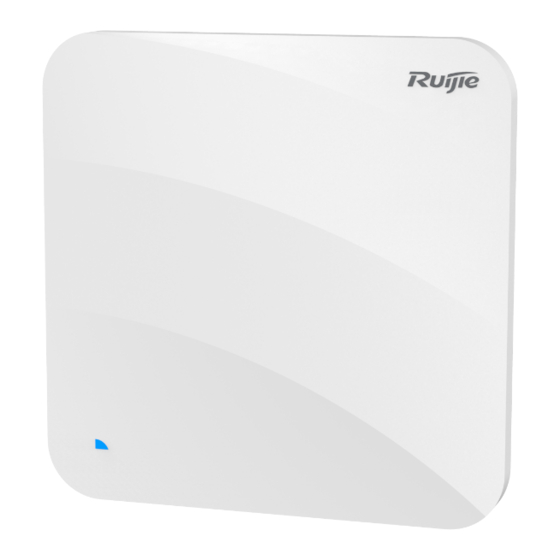
Page 6: Product Image
5. Console Port LAN1 port is PoE+ capable. LAN3 port is accessible only to Ruijie’s IoT modules (12V/0.125mA, MAX:1.5W). Connecting other modules may cause damage. By default, powering capacity of the LAN3 port is disabled. You can choose to power the device by either a DC adapter or a PoE device. But you cannot use both at one time. -
Page 7: Led Indicators
Restores the factory default settings. than 3s 1.4 Power Sources The AP can be powered either with a power adapter or through a PoE+ device. If an adapter is chosen to power the AP, make sure it meets the requirements set by Ruijie. -
Page 8: Cooling Solution
Hardware Installation and Reference Guide Product Overview · 1.5 Cooling Solution The AP features a fanless design. Leave sufficient space surrounding the AP when installing the AP to permit proper airflow for ventilation. -
Page 9: Preparing For Installation
Hardware Installation and Reference Guide Preparing for Installation · 2 Preparing for Installation To prevent device damage and physical injury, please read the safety recommendations carefully as described in this chapter. Recommendations do not cover all possible hazardous situations. 2.1 Installation The AP must be installed indoors. -
Page 10: Temperature And Humidity
Hardware Installation and Reference Guide Preparing for Installation Do not place the device in a damp/wet location. Do not let any liquid enter the chassis. · Keep the AP far away from grounding or lightning protection devices for power equipment. ... -
Page 11: Power Supply
The DC input power should be greater than the power actually consumed by the system. The input power for the RG-AP850-I(V2) should not be lower than 25.5W. Use DC power adapters with specifications recommended by Ruijie. Please use Ruijie certified PoE injectors. - Page 12 Hardware Installation and Reference Guide Preparing for Installation Verify that all parts are installed and debugged. · Brackets Screws Items Mounting brackets Product quick installation guide Packing list The above listed items are for general situations, and contents may vary in the actual shipment. The purchasing order shall prevail in any case.
-
Page 13: Installing The Access Point
Hardware Installation and Reference Guide Installing the Access Point · 3 Installing the Access Point The RG-AP850-I(V2) series must be fixed and installed indoors. Before installing the AP, make sure you have carefully read the requirements described in Chapter 2. 3.1 Installation Flowchart 3.2 Before You Begin Before installing the AP, verify that:... - Page 14 Hardware Installation and Reference Guide Installing the Access Point Disconnect the device before cleaning it. · Do not wipe the device with a damp cloth. Do not wash the device with liquid. Do not open the enclosure when the AP is working. ...
- Page 15 Hardware Installation and Reference Guide Installing the Access Point Figure 3-3 Mounting the AP on the Bracket · The AP can be installed in any of four directions on the mounting bracket depending on how you route the Ethernet cable. The square feet should fit easily into the mounting slots.
-
Page 16: Optional) Securing The Access Point
Figure 3-6 Mounting the AP on the Bracket When mounting the AP on the wall, keep the Ruijie logo pointed upwards. The square feet should fit easily into the mounting slots. Do not forcibly push the AP into the slots. -
Page 17: Removing The Access Point
3.6 Removing the Access Point If the hidden lock is enabled, attach the front part of the key to the edge of the mounting bracket (keep the Ruijie key logo facing the top panel of the AP). Slide the key along with the four edges of the mounting bracket, and attempt to insert the key into the keyhole. -
Page 18: Connecting Cables
The console port is used only when you want to configure the AP manually. Avoid bending the cable in a small radius close to the connector. Ruijie recommends that you do not use Ethernet cables with protective sleeves as they could make installation of Ethernet cables more difficult. -
Page 19: System Debugging
Hardware Installation and Reference Guide System Debugging · 4 System Debugging 4.1 Setting up a Debugging Environment Use a power adapter or PoE to power the AP. Setting up the Environment Verify that the AP is properly connected to the power source. ... -
Page 20: Monitoring And Maintenance
Hardware Installation and Reference Guide Monitoring and Maintenance · 5 Monitoring and Maintenance 5.1 Monitoring You can observe the LED to monitor the AP in operation. CLI Commands Run related commands on the command line interface (CLI) on the wireless controller to remotely monitor the configurations and status of the AP. -
Page 21: Troubleshooting Flowchart
Hardware Installation and Reference Guide Troubleshooting · 6 Troubleshooting 6.1 Troubleshooting Flowchart 6.2 Troubleshooting LED does not light up after the AP is powered on If you use PoE power supply, verify that the power source is IEEE 802.11af compliant; then verify that the cable is properly connected. - Page 22 Hardware Installation and Reference Guide Troubleshooting First, follow the two steps above. · Verify that the AP is correctly configured. Adjust the angle of the antennas. Move the client device to adjust the distance between the client and the AP. LED keeps blinking red If the LED blinking red for a long time, this indicates that the Ethernet port is not connected.
-
Page 23: Appendix A Connectors And Media
Hardware Installation and Reference Guide Appendix A Connectors and Media · Appendix A Connectors and Media 1000BASE-T/100BASE-TX/10BASE-T The 1000BASE-T/100BASE-TX/10BASE-T is a 10/100/1000 Mbps auto-negotiation port that supports auto MDI/MDIX. Compliant with IEEE 802.3ab, 1000BASE-T requires Category 5e 100-ohm UTP or STP (STP is recommended) with a maximum distance of 100 meters (328 feet). -
Page 24: Appendix B Cabling Recommendations
Hardware Installation and Reference Guide Appendix B Cabling Recommendations · Appendix B Cabling Recommendations During installation, route cable bundles upward or downward along the sides of the rack depending on the actual situation in the equipment room. All cable connectors should be placed at the bottom of the cabinet rather than be exposed outside of the cabinet. - Page 25 Hardware Installation and Reference Guide Appendix B Cabling Recommendations · If cables are to be bent, bind them first but do not tie cable ties within the bend to avoid stress on the cables, which may otherwise cause the wires inside to break, as shown in Figure B-3. Figure B-3 Do Not Tie Cable Ties within the Bend ...
- Page 26 Hardware Installation and Reference Guide Appendix B Cabling Recommendations · 3. Spring washer 1. Flat washer Note 4. Flat washer 2. Nut When using a stiff cable, fix it near the cable lug to avoid stress on the lug and cable. ...
Need help?
Do you have a question about the RG-AP850-I-V2 Series and is the answer not in the manual?
Questions and answers