
Related Manuals for Ruijie RG-AP810-L


Summary of Contents for Ruijie RG-AP810-L
- Page 1 Ruijie RG-AP810-L Access Point Hardware Installation and Reference Guide Document Version: V1.1 Date: 2022.9.7 Copyright © 2022 Ruijie Networks...
- Page 2 Due to product version upgrades or other reasons, the content of this document will be updated from time to time. Ruijie Networks reserves the right to modify the content of the document without any notice or prompt. This manual is for reference only. Ruijie Networks endeavors to ensure content accuracy and will not shoulder...
-
Page 3: Preface
Preface Intended Audience This document is intended for: Network engineers Technical support and servicing engineers Network administrators Technical Support Ruijie Networks Website: https://www.ruijienetworks.com/ Technical Support Website: https://ruijienetworks.com/support Case Portal: http://caseportal.ruijienetworks.com Community: http://community.ruijienetworks.com ... - Page 4 Note This manual provides the device installation steps, hardware troubleshooting, module technical specifications, and specifications and usage guidelines for cables and connectors. It is intended for the users who have some experience in installing and maintaining network hardware. At the same time, it is assumed that the users are already familiar with the related terms and concepts.
-
Page 5: Table Of Contents
Hardware Installation and Reference Guide Product Overview Contents Preface ..............................I 1 Product Overview ........................... 1 1.1 Appearance ..........................1 1.2 Package Contents ........................3 1.3 Technical Specifications ......................3 1.3.1 Size and Weight ......................3 1.3.2 RF ........................... 4 1.3.3 Ports .......................... - Page 6 Hardware Installation and Reference Guide Product Overview 2.1.4 Storage Safety ......................9 2.2 Installation Environment Requirements ................9 2.2.1 Bearing Requirements ....................9 2.2.2 Ventilation Requirements ................... 9 2.2.3 Space Requirement ..................... 9 2.2.4 Temperature/Humidity Requirements ............... 9 2.2.5 Cleanliness Requirements ..................10 2.2.6 Anti-interference Requirements ................
- Page 7 Hardware Installation and Reference Guide Product Overview 3.4.2 Wall Mounting ......................15 3.5 Securing the Access Point ....................17 3.6 Removing the Access Point ....................18 3.7 Connecting Cables ......................... 19 3.8 Bundling Cables ........................19 3.8.1 Precautions ......................... 19 3.8.2 Bundling Steps ......................
- Page 8 Hardware Installation and Reference Guide Product Overview 5.1 Monitoring ..........................22 5.1.1 LED ..........................22 5.1.2 CLI Commands ......................22 5.2 Remote Maintenance ......................22 5.3 Hardware Maintenance ......................22 6 Troubleshooting ..........................23 6.1 Troubleshooting Flowchart ....................23 6.2 Typical Troubleshooting Cases .................... 23 6.2.1 Ethernet Port Does Not Work After Being Connected to an Ethernet Cable ..
- Page 9 Hardware Installation and Reference Guide Product Overview 7.2 Cabling Recommendations ....................27 7.3 Power Supply ......................... 30...
-
Page 10: Product Overview
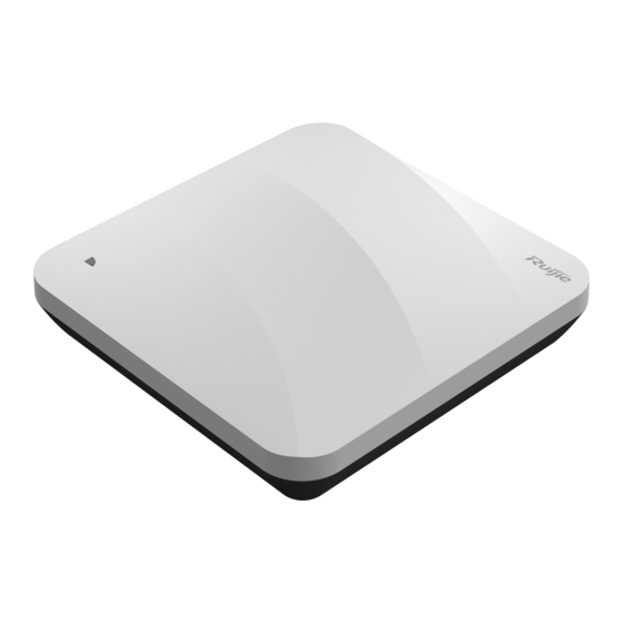
Product Overview The RG-AP810-L AP is a dual-radio access point compliant with the IEEE 802.11ax standard. The RG-AP810- L AP provides a combined data rate of 1.775 Gbps, with up to 574 Mbps in the 2.4 GHz band and 1.201 Gbps in the 5 GHz band, available for flexible deployments in the field of education, government, finance and business. - Page 11 Hardware Installation and Reference Guide Product Overview Figure 1-2 Front Panel Table 1-1 Front Panel Item Description Indicate the operation status of device. Figure 1-3 Side View...
-
Page 12: Package Contents
Connect to the DC power adapter to supply power to the DC power plug Package Contents Table 1-3 Package Contents Item Quantity RG-AP810-L Access Point Mounting Bracket Wall Anchor Phillips Pan Head Screws M4 x 20 Warranty Card Quick Start Guide Technical Specifications 1.3.1... - Page 13 Hardware Installation and Reference Guide Product Overview Bracket Dimensions 120 mm×120 mm×8 mm (4.72 in. x 4.72 in. x 0.31 in.) (W x D x H) Mounting Hole 53 mm (2.09 in.) Pattern Mounting Hole 6.5 mm (0.26 in.) Diameter 1.3.2 Table 1-5 RF Item...
-
Page 14: Ports
Hardware Installation and Reference Guide Product Overview MIMO-OFDM: BPSK, QPSK, 16QAM, 64QAM, 256QAM and 1024QAM OFDMA 11b: -96dBm(1Mbps), -93dBm(5Mbps), -89dBm(11Mbps) 11a/g: -91dBm(6Mbps), -85dBm(24Mbps), -80dBm(36Mbps), -74dBm(54Mbps) 11n: -90dBm@MCS0, -70dBm@MCS7, -89dBm@MCS8, -68dBm@MCS15 Receive 11ac: HT20: -88dBm(MCS0), -63dBm(MCS9) Sensitivity 11ac: HT40: -85dBm(MCS0), -60dBm(MCS9) 11ac: HT80: -82dBm(MCS0), -57dBm(MCS9) 11ax: HE80: -82dBm(MCS0), -57dBm(MCS9),-52dBm(MCS11) 1.3.3... -
Page 15: Environment And Reliability
Hardware Installation and Reference Guide Product Overview 1.3.5 Environment and Reliability Table 1-8 Environment and Reliability Item Description Operating: -10° C to 50° C (14° F to 122° F) Storage: -40° C to 70° C (-40° F to 158° F) Temperature At a height between 3000 m (9842.52 ft.) to 5000 m (16404.20 ft.) above the sea level, every time the altitude increases by 220 m (721.78 ft.), the maximum... - Page 16 Hardware Installation and Reference Guide Product Overview Indicator Blinking Description Color Frequency The software system is running normally, and the AP is working normally Steady blue None but no wireless users are online. On for 1s Blinking The software system is running normally. The AP is working normally and blue wireless users are online.
-
Page 17: Preparing For Installation
Hardware Installation and Reference Guide Preparing for Installation Preparing for Installation Safety Precautions Note ● To avoid personal injury and device damage, carefully read the safety precautions before you install the device. ● The following safety precautions may not cover all possible dangers. 2.1.1 General Safety Precautions ... -
Page 18: Storage Safety
Hardware Installation and Reference Guide Preparing for Installation Learn about the position of the indoor emergency power switch before installation. Cut off the power switch in case of accidents. Check the device carefully before shutting down the power supply. ... -
Page 19: Cleanliness Requirements
Hardware Installation and Reference Guide Preparing for Installation Note The ambient temperature and humidity of the device are measured at the point that is 1.5 m (59.06 in.) above the floor and 0.4 m (15.75 in.) before the device when there is no protective plate in front or at the back of the device. -
Page 20: Anti-Interference Requirements
Hardware Installation and Reference Guide Preparing for Installation 2.2.6 Anti-interference Requirements Take interference prevention measures for the power supply system. Keep the device away from the grounding equipment or lightning and grounding equipment of the power device as much as possible. ... -
Page 21: Installing The Access Point
Hardware Installation and Reference Guide Installing the Access Point Installing the Access Point The RG-AP810-L AP must be fixed and installed indoors. Caution Before installing the device, make sure you have carefully read the requirements described in Chapter 2. Installation Flowchart... -
Page 22: Precautions
Hardware Installation and Reference Guide Installing the Access Point The position of the indoor emergency power switch is learned before installation. The power switch is cut off in case of accidents. For ceiling-mounted or wall-mounted AP, the mounting bracket size, mounting hole pattern and diameter should meet the requirements in Table 1-4. -
Page 23: Installing The Access Point
Hardware Installation and Reference Guide Installing the Access Point Disconnect the device before cleaning it. Do not wipe the device with a damp cloth. Do not wash the device with liquid. Do not open the enclosure when the device is working. ... -
Page 24: Wall Mounting
Hardware Installation and Reference Guide Installing the Access Point Figure 3-3 Aligning the Square Feet with the Mounting Holes Caution Install the Ethernet cables before mounting the AP on the bracket. (3) Slide the AP onto the bracket in the opposite direction of the arrow on the mounting bracket until it clicks into place. - Page 25 Hardware Installation and Reference Guide Installing the Access Point Figure 3-5 Attaching the Mounting Bracket to the Wall (2) Align the square feet on the rear of the AP with the mounting holes on the bracket. Figure 3-6 Aligning the Square Feet with the Mounting Holes Caution Install the Ethernet cables before mounting the AP on the bracket.
-
Page 26: Securing The Access Point
Installing the Access Point Caution ● When mounting the AP on the wall, keep the Ruijie logo pointed upwards. ● The square feet should fit easily into the mounting slots. Do not forcibly push the AP into the slots. ●... -
Page 27: Removing The Access Point
Hardware Installation and Reference Guide Installing the Access Point Caution Install the Ethernet cables before mounting the AP on the bracket. Removing the Access Point (1) If the AP is installed on the ceiling, hold the AP in your hands and slide it sideways and away from the bracket in the LAN port direction. -
Page 28: Connecting Cables
Hardware Installation and Reference Guide Installing the Access Point Connecting Cables Connect UTP/STP to the LAN/PoE port on the AP. See Chapter 7.1 Connectors and Media for supported wiring of twisted pairs. Caution By default, baud rate is set to 9600, data bit 8, parity none, stop bits 1 and flow control none on the Console port of the AP. -
Page 29: Checking Cable Connection
Hardware Installation and Reference Guide Installing the Access Point 3.9.2 Checking Cable Connection Make sure the UTP/STP cable matches the interface type. Make sure cables are properly bundled. 3.9.3 Checking Power Supply Make sure all power ports are properly connected and compliant with safety requirement. ... -
Page 30: Verifying Operating Status
Hardware Installation and Reference Guide Verifying Operating Status Verifying Operating Status Configuring the Environment Use a power adapter or PoE to power the AP. Setting up the Environment Verify that the AP is properly connected to the power source. ... -
Page 31: Monitoring And Maintenance
Hardware Installation and Reference Guide Monitoring and Maintenance Monitoring and Maintenance Monitoring 5.1.1 You can observe the LED to monitor the AP in operation. 5.1.2 CLI Commands You can run related commands on the command line interface (CLI) of the device to remotely monitor the configurations and status of the AP. -
Page 32: Troubleshooting
Hardware Installation and Reference Guide Troubleshooting Troubleshooting Troubleshooting Flowchart Typical Troubleshooting Cases 6.2.1 Ethernet Port Does Not Work After Being Connected to an Ethernet Cable Check whether the device on the other end of the Ethernet is working normally, and then check whether the Ethernet cable matches the current working speed. -
Page 33: Indicator Remains Red For A Long Time
Hardware Installation and Reference Guide Troubleshooting 6.2.3 Indicator Remains Red for a Long Time If the indicator stays red for a long time, it means that the Ethernet port cannot be connected. Check the connection on the Ethernet port. 6.2.4 Indicator Remains Green for a Long Time The device needs to be initialized when it is powered on. -
Page 34: Appendix
Hardware Installation and Reference Guide Appendix Appendix Connectors and Media 1000BASE-T/100BASE-TX/10BASE-T The 1000BASE-T/100BASE-TX/10BASE-T is a 10/100/1000 Mbps auto-negotiation port that supports auto MDI/MDIX. Compliant with IEEE 802.3ab, 1000BASE-T requires Category 5e 100-ohm UTP or STP (STP is recommended) with a maximum distance of 100 meters (328 feet). 1000BASE-T requires all four pairs of wires be connected for data transmission, as shown in Figure 7-1. - Page 35 Hardware Installation and Reference Guide Appendix Figure 7-3 100BASE-TX/10BASE-T Connection...
- Page 36 Hardware Installation and Reference Guide Appendix Cabling Recommendations During installation, route cable bundles upward or downward along the sides of the rack depending on the actual situation in the equipment room. All cable connectors should be placed at the bottom of the cabinet rather than be exposed outside of the cabinet.
- Page 37 Hardware Installation and Reference Guide Appendix Figure 7-5 Cutting off Excess Cable Tie ○ If cables are to be bent, bind them first but do not tie cable ties within the bend to avoid stress on the cables, which may otherwise cause the wires inside to break, as shown in Figure 7-6. Figure 7-6 Do Not Tie Cable Ties within the Bend ○...
- Page 38 Hardware Installation and Reference Guide Appendix Figure 7-7 Fastening Cable Lugs Note 1. Flat washer 3. Spring washer 2. Nut 4. Flat washer ○ When using a stiff cable, fix it near the cable lug to avoid stress on the lug and cable. ○...
- Page 39 Hardware Installation and Reference Guide Appendix Power Supply DC power adapter: Input voltage: 48 V Rated current: 0.3 A Technical Specifications of the DC Power Connector Inner Diameter Outer Diameter Depth Polarity Inner pole: positive 2.0 mm (0.08 in.) 6.3 mm (0.25 in.) 9.8 mm (0.39 in.) Outer pole: negative...
Need help?
Do you have a question about the RG-AP810-L and is the answer not in the manual?
Questions and answers