Siemens FC700A Installation And Hardware Commissioning
Fire detection system
Hide thumbs
Also See for FC700A:
- System planning manual (70 pages) ,
- Hardware description (108 pages) ,
- Maintenance instructions manual (20 pages)

Related Manuals for Siemens FC700A


Summary of Contents for Siemens FC700A
- Page 1 FC700A Fire detection system Installation and Hardware Commissioning Building Technologies Fire Safety & Security Products...
- Page 2 Data and design subject to change without notice. / Supply subject to availability. © Siemens Switzerland Ltd 2004-2008 We reserve all rights in this document and in the subject thereof. By acceptance of the document the recipient acknowledges these rights and undertakes not to publish the document nor the subject thereof in full or in part, nor to make them available to any third party without our prior express written authorization, nor to use it for any purpose other than for which it was delivered to him.
-
Page 3: Table Of Contents
About this document ................5 Safety regulations ...................7 Signal words and symbols ................7 2.1.1 Signal words and their meaning..............7 2.1.2 Symbols and their meaning ..............7 2.1.3 Classification and meaning of additional symbols ........8 Safety-relevant working instructions ............8 Installation .....................10 Space for parallel indicator panel............10 Housing installation .................11 Protection of the installed housing ............12 Commissioning ..................13... - Page 4 Ground fault monitoring...............30 14.1 Modules with ground fault monitoring .............30 14.1.1 Settings of the modules in the factory.............30 14.2 Test ground fault monitoring ..............30 Install modules ..................31 Connection periphery ................32 First switch-on..................33 17.1 Battery charging module E3C011 ............33 17.2 Control terminal B3Q700 ('FC'/'FT') ............33 Read in ....................34 18.1 Read in of the hardware modules ............34...
-
Page 5: About This Document
About this document Purpose This document describes the installation and commissioning of the hardware mod- ules of the control unit FC700A. The consistent adherence to these instructions is a prerequisite for a safe application. Target group This product documentation and the work instructions are aimed at the following persons, who have a particular function and have the corresponding training and qualification. - Page 6 Disregard of the safety regulations Before they are delivered, products are tested to ensure they function correctly when used properly. Siemens disclaims all liability for damage or injuries caused by the incorrect application of the instructions or disregard of warnings of danger contained in the documentation.
-
Page 7: Safety Regulations
Safety regulations Safety regulations This chapter describes the danger levels and the relevant safety regulations appli- cable for the use of our products. Please read the work instructions as well as the chapter ”About this document” thoroughly before beginning any work. Signal words and symbols 2.1.1 Signal words and their meaning... -
Page 8: Classification And Meaning Of Additional Symbols
Safety regulations 2.1.3 Classification and meaning of additional symbols Tips and information Refers to extremely important or critical decisions to be taken into account before continuing the work. Safety-relevant working instructions Country-specific standards The products are developed and produced in compliance with the relevant interna- tional and European safety standards. - Page 9 Safety regulations Testing the product operability Evacuate and cordon off extinguishing sector. Inform people about the possibility of occurring fog and noise. Inform people before testing of alarm devices; take the possibility of panic reac- tions into account. Inform the alarm and fault receiving stations connected to the system before running the tests.
-
Page 10: Installation
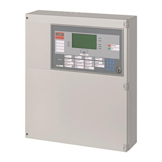
Installation Installation Housing set FC700A (H38G320) Fire detection system FC700A as compact control unit for up to 10 plug-in – modules, with built-in operating terminal (B3Q700). Space for parallel indicator panel B3Q700 H23B010 B3R051 Legend: Housing set incl. control terminal (B3Q700) and cover plate H23B010... -
Page 11: Housing Installation
Installation Housing installation min. 1m 1.7 m min. 50 mm 8 mm Procedure: 1. Open housing (4) with hexagon wrench No. 3 (included in the housing set). 2. Remove converter B2F020 (6) (put it back afterwards) 3. Determine place of installation. 4. -
Page 12: Protection Of The Installed Housing
Installation Protection of the installed housing During the building phase the carton it was delivered in can protect the installed housing. Building Technologies 007828_b_en_-- Fire Safety & Security Products 09.2008... -
Page 13: Commissioning
Commissioning Commissioning Commissioning the system Connection cable from mains, series fuse ≤ 10A / IEC950 10 kg strain relief PG11 screwed cable gland Requirements: The following work must be completed 1. Control unit installed and detection lines ready for connection (1). 2. -
Page 14: Preparation
Commissioning Preparation Control unit FC700A Connect mains cable and supply line (2) – Install possible additional modules chassis and attach connection cable in ac- – cordance with the system documentation Set I-Bus address on all modules / set switches and jumpers –... -
Page 15: Installation Of Hardware
Installation of hardware Installation of hardware Installation of auxiliary p.c.b. chassis Pos. Module Preparation Default Module chassis Screw module chassis provisory on the housing Mounted in housing front panel (mount again later) see chapter 15 Connection cable with terminal block Mount on module chassis –... -
Page 16: B3Q700 Control Terminal For Use As 'Fc' Or 'Ft
B3Q700 Control terminal for use as 'FC' or 'FT' Pos. 1 and 6 in the following description is only relevant if B3Q700 is used as replacement for FC700A. By ordering FC700A or B3Q700 (for FT700A) the Pos. 1 and 6 is already done by default. Pos. Module... -
Page 17: Line Modules
Line modules Line modules E3M080 Line module "Collective" Pos. Module Preparation Default Programming switch 'S3': I-Bus address Set according to the system documentation Address 0 (1… 14) Programming switch ''S4-2': Evaluation of Change to 'ON' if short circuit is to be inter- To 'OFF' short circuit = fault line short circuit preted as ALARM... -
Page 18: Lon Module
LON module LON module E3I040 I-Bus/LON module Pos. Module Preparation Default Programming switch 'S3': I-Bus address Set according to the system documentation Address 0 (1… 14) Resistor 'R60': line termination element If the LON-Bus is wired as "free topology", 'R60' 100Ω... -
Page 19: Control Modules
Control modules Control modules E3L020 Control module 'I/O' Pos. Module Preparation Default Programming switch 'S3': I-Bus address Set according to the system documentation Address 0 (1… 14) Maintenance switch 'S2': Activate test LEDs Set to 'ON' for commissioning To 'OFF' 'H1'..'H16' E3L030 Control module 'VdS' Pos. -
Page 20: E3G050 Control Module 'Contacts
Control modules E3G050 Control module 'Contacts' Pos. Module Preparation Default Programming switch 'S3': I-Bus address Set according to the system documentation Address 0 (1… 14) Maintenance switch 'S2': Activate test LEDs Set to 'ON' for commissioning To 'OFF' 'H1'..'H8' E3G060 Control module 'monitored' Pos. -
Page 21: E3G070 Control Module 'Universal
Control modules E3G070 Control module 'Universal' Pos. Module Preparation Default Programming switch 'S3': I-Bus address Set address to 15 Address 0 Maintenance switch 'S2': Activate test LEDs Set to 'ON' for commissioning To 'OFF' 'H1'... 'H11' Re-solder if necessary, according to the system 0Ω... -
Page 22: Control Terminal And Floor Repeater Panels
Control terminal and floor repeater panels Control terminal and floor repeater panels 10.1 FT700A (B3Q700) Control terminal Control terminal see chapter 6 10.2 B3R051 Parallel indicator panel Pos. Module Preparation Default Resistor array 'N3' Remove all but 1 device, see description in Equipped document 007831 Programming switch 'S1': Equipment ad-... -
Page 23: K3G060 Relay P.c.b
Control terminal and floor repeater panels 10.4 K3G060 Relay p.c.b. Pos. Module Preparation Default Mounting plate Remove according to the system documenta- Mounted tion, see description in document 007831 Programming connectors 'X1'..'X24': Set according to the system documentation, see 'Open' (relay contact is potential- Programming of external potential + or –... -
Page 24: K3I110 Lon I/O P.c.b
Control terminal and floor repeater panels 10.6 K3I110 LON I/O p.c.b. Pos. Module Preparation Default Programming switch 'S3': LON-Bus address Set according to the system documentation Set Address 0 Jumper 'X30': Ground fault monitoring Set according to the system documentation, see To 'right' (not monitored) 'Inputs' description in document 007831... -
Page 25: B3Q590/595 Floor Repeater Panel With Control Functions
Control terminal and floor repeater panels 10.8 B3Q590/595 Floor repeater panel with control functions Pos. Module Preparation Default Programming switch 'S3': LON-Bus address According to the system documentation Set Address 0 Programming switch 'S4-1': Buzzer off Set 'S4-1' to 'ON' for commissioning Set to 'OFF' Resistor 'R1': line termination element Stub line: if B3Q59x is not the last device, re-... -
Page 26: Printer
Printer Printer 11.1 E3I020 RS232 module Never connect or disconnect the flat cable when power supply is connected. NOTE This may cause the system to restart. Building Technologies 007828_b_en_-- Fire Safety & Security Products 09.2008... -
Page 27: Gateway Fg700A
Gateway FG700A Gateway FG700A 12.1 E3H020 C-Bus Gateway Take precautions against voltage surges when inserting RAM modules and NOTE EPROM's. Make sure the modules are pushed fully in their slots. Pos. Module Preparation Default Select EPROM set Insert (consider positions for 'ODD' and 'EVEN') Not inserted CKQ0076x (2x 512Kx8Bit) Programming switch 'S3': C-Bus address... -
Page 28: E3H021 C-Bus Gateway
Gateway FG700A 12.2 E3H021 C-Bus Gateway Pos. Module Preparation Default SRAM – 8x512Kx8Bit Flash-ROM – Program file for E3H021 FG700A CKY0076x Programming switch ’S3’: Set according to the system documentation Address 0 C-Bus address Programming switch ’S5’: Set according to the system documentation, see set to ’OFF’... -
Page 29: Power Supply
Pos. Module Preparation Default Programming switch 'S3': I-Bus address Set address to 16 if used in FC700A Address 0 Set address to 0 by using as auxiliary power supply (in separate housing) Programming switch 'S2': Select battery Set to the battery type used, see description in... -
Page 30: Ground Fault Monitoring
Ground fault monitoring Ground fault monitoring 14.1 Modules with ground fault monitoring For more detailed information on the modules with ground fault monitoring, their application, function and programming -> see document 007831, chapter 'Ground fault monitoring'. 14.1.1 Settings of the modules in the factory The ground fault monitoring is inactive on all modules, i.e. -
Page 31: Install Modules
Install modules Install modules NOTE Do never connect the I-Bus from other stations together! Procedure: 1. Install modules in accordance with the system documentation and fix them 2. Attach I-Bus flat cable (1) (ensure good contact) 3. Attach supply cable (2). Be aware that the I-Bus supply is wired correct Never connect or disconnect the flat cable and the supply cable when power NOTE supply is switched on! -
Page 32: Connection Periphery
Connection periphery Connection periphery For the connection of periphery devices see the connection diagram inside the door or in the docu- ment 007831 'Hardware description'. Building Technologies 007828_b_en_-- Fire Safety & Security Products 09.2008... -
Page 33: First Switch-On
First switch-on First switch-on 1. Check whether the batteries are connected. 2. Apply mains voltage, observe the safety regulations in Chapter 2 The stations 'FC'/'FT' load a basic configuration stored in Flash into the RAM. – After approx. 2 min., this start-up procedure is concluded. 17.1 Battery charging module E3C011 Green LED 'H501-2' (2) 'Mains operation' lights up. -
Page 34: Read In
5. Check whether all modules are shown with the correct I-Bus setting 6. If wrong, change the data where necessary to get the right situation 7. If ok, download the data; select the menu "Communication" -> "Download data (-> FC700A)" 18.2 Read in of devices on a loop Procedure: 1. -
Page 35: Device Activation For Testing/Upgrading A System
Device activation for testing/upgrading a system Device activation for testing/upgrading a system 19.1 Automatic detectors RG320 DZ1193 RE6T RE10 LE3 / StabexHF DZ1193 -> See document 1462 RE6/RE6T/RE10 -> See document 1164 -> See document 257 DF11.. -> See document 1673 DLO…... -
Page 36: Input/Output Modules
Device activation for testing/upgrading a system 19.3 Input/output modules Pos. Input module / Output module Procedure: DC1192 / ABI320A Addressing by alarming, press key (3), the addressing is indicated by LED (4) flashing EB…/AB…/ABI… Building Technologies 007828_b_en_-- Fire Safety & Security Products 09.2008... - Page 37 Device activation for testing/upgrading a system Building Technologies 007828_b_en_-- Fire Safety & Security Products 09.2008...
- Page 38 Siemens Switzerland Ltd. © Siemens Switzerland Ltd 2004-2008 Building Technologies Division International Headquarters Data and design subject to change without notice. Gubelstrasse 22 6301 Zug, Switzerland Tel. +41 41 - 724 24 24 Fax +41 41 - 723 35 22 www.siemens.com/buildingtechnologies...
Need help?
Do you have a question about the FC700A and is the answer not in the manual?
Questions and answers