SICK DUSTHUNTER T Operating Instructions Manual
Dust concentration monitor
Hide thumbs
Also See for DUSTHUNTER T:
- Operating instructions manual (142 pages) ,
- Operating instructions manual (552 pages)

Related Manuals for SICK DUSTHUNTER T


Summary of Contents for SICK DUSTHUNTER T
- Page 1 Title Page MMMOPERATING INSTRUCTIONS MMMI O P E R A T I N G I N S T R U C T I O N S DUSTHUNTER T Dust Concentration Monitor Installation, Operation, Maintenance...
- Page 2 Original document This document is an original document of SICK AG. O P E R A T I N G I N S T R U C T I O N S | DUSTHUNTER T 8012428/YWL2/3-0/2016-08| SICK Subject to change without notice...
-
Page 3: Table Of Contents
2.3.2 Device configuration..............33 SOPAS ET (PC program) ................34 8012428/YWL2/3-0/2016-08 | SICK O P E R A T I N G I N S T R U C T I O N S | DUSTHUNTER T Subject to change without notice... - Page 4 Scaling the measuring system for transmission measurement. 67 4.2.4 Entering application-specific parameters ........69 O P E R A T I N G I N S T R U C T I O N S | DUSTHUNTER T 8012428/YWL2/3-0/2016-08 | SICK Subject to change without notice...
- Page 5 Warning and error messages in the SOPAS ET program ..108 6.3.3 Replacing the fuse ..............110 8012428/YWL2/3-0/2016-08 | SICK O P E R A T I N G I N S T R U C T I O N S | DUSTHUNTER T Subject to change without notice...
- Page 6 MCU with integrated purge air supply ........125 7.5.3 Optional external purge air unit ..........125 O P E R A T I N G I N S T R U C T I O N S | DUSTHUNTER T 8012428/YWL2/3-0/2016-08 | SICK Subject to change without notice...
-
Page 7: Important Information
Refit any contact protection removed before switching the power voltage back on again. 8012428/YWL2/3-0/2016-08| SICK O P E R A T I N G I N S T R U C T I O N S | DUSTHUNTER T Subject to change without notice... -
Page 8: Symbols And Document Conventions
The DUSTHUNTER T measuring system is not approved for use in potentially explosive ● atmospheres. O P E R A T I N G I N S T R U C T I O N S | DUSTHUNTER T 8012428/YWL2/3-0/2016-08| SICK Subject to change without notice... -
Page 9: Responsibility Of User
The specified maintenance and inspection tasks are carried out regularly by qualified, experienced personnel. 8012428/YWL2/3-0/2016-08| SICK O P E R A T I N G I N S T R U C T I O N S | DUSTHUNTER T Subject to change without notice... - Page 10 Ensure the device can be switched off with a power isolating switch/circuit breaker in accor- dance with EN 61010-1. O P E R A T I N G I N S T R U C T I O N S | DUSTHUNTER T 8012428/YWL2/3-0/2016-08| SICK...
-
Page 11: Product Description
Transmission, opacity and relative opacity are usually specified in percent. Extinction: -- - 8012428/YWL2/3-0/2016-08| SICK O P E R A T I N G I N S T R U C T I O N S | DUSTHUNTER T Subject to change without notice... -
Page 12: Response Time
Measured value with response time Process change Response time t in s O P E R A T I N G I N S T R U C T I O N S | DUSTHUNTER T 8012428/YWL2/3-0/2016-08| SICK Subject to change without notice... -
Page 13: Function Check
Changes to the interval time are first effective after the next start timepoint. ● 8012428/YWL2/3-0/2016-08| SICK O P E R A T I N G I N S T R U C T I O N S | DUSTHUNTER T Subject to change without notice... - Page 14 “Factory settings”, page “Setting the analog outputs parameters”, page 76). O P E R A T I N G I N S T R U C T I O N S | DUSTHUNTER T 8012428/YWL2/3-0/2016-08| SICK Subject to change without notice...
- Page 15 Control reflector (only on the sender side) Pivoted shutter 8012428/YWL2/3-0/2016-08| SICK O P E R A T I N G I N S T R U C T I O N S | DUSTHUNTER T Subject to change without notice...
-
Page 16: Device Components
As standard, each sender/receiver unit is connected to an MCU control unit via the con- nection line. O P E R A T I N G I N S T R U C T I O N S | DUSTHUNTER T 8012428/YWL2/3-0/2016-08| SICK... -
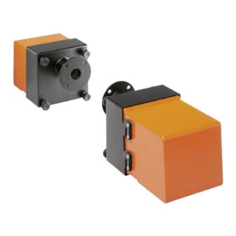
Page 17: Sender/Receiver Unit
à Purge air connection Connection for connection cable to MCU 8012428/YWL2/3-0/2016-08| SICK O P E R A T I N G I N S T R U C T I O N S | DUSTHUNTER T Subject to change without notice... - Page 18 Optics, electronics and mechanical components can then be easily accessed for maintenance work. O P E R A T I N G I N S T R U C T I O N S | DUSTHUNTER T 8012428/YWL2/3-0/2016-08| SICK...
- Page 19 - 2: With contamination measurement on both sides Self-alignment: - 0: Without - 1: With 8012428/YWL2/3-0/2016-08| SICK O P E R A T I N G I N S T R U C T I O N S | DUSTHUNTER T Subject to change without notice...
-
Page 20: Reflector
Knurled screw Purge air connection Flange O P E R A T I N G I N S T R U C T I O N S | DUSTHUNTER T 8012428/YWL2/3-0/2016-08| SICK Subject to change without notice... -
Page 21: Flange With Tube
Securing bolt Material St 37 or 1.4571 8012428/YWL2/3-0/2016-08| SICK O P E R A T I N G I N S T R U C T I O N S | DUSTHUNTER T Subject to change without notice... -
Page 22: Mcu Control Unit
T100/200 Limit value ● RS485 for sensor ● connection O P E R A T I N G I N S T R U C T I O N S | DUSTHUNTER T 8012428/YWL2/3-0/2016-08| SICK Subject to change without notice... -
Page 23: Versions
Processor board Display module (option) Interface module (option) 8012428/YWL2/3-0/2016-08| SICK O P E R A T I N G I N S T R U C T I O N S | DUSTHUNTER T Subject to change without notice... - Page 24 124)) is a separate part of the measuring system and must be ordered separately. O P E R A T I N G I N S T R U C T I O N S | DUSTHUNTER T 8012428/YWL2/3-0/2016-08| SICK...
-
Page 25: Type Code
- N: Without EX certification Software - E: Emission measurement 8012428/YWL2/3-0/2016-08| SICK O P E R A T I N G I N S T R U C T I O N S | DUSTHUNTER T Subject to change without notice... -
Page 26: Options
Menu Display of main menu and selection of submenus O P E R A T I N G I N S T R U C T I O N S | DUSTHUNTER T 8012428/YWL2/3-0/2016-08| SICK Subject to change without notice... - Page 27 – The MCU and the MCU remote control unit are interlocked (it is not possible to oper- ate both MCUs at the same time). 8012428/YWL2/3-0/2016-08| SICK O P E R A T I N G I N S T R U C T I O N S | DUSTHUNTER T Subject to change without notice...
-
Page 28: Optional External Purge Air Unit
A weatherproof cover is available for use outdoors (see “Weatherproof covers”, page 122). O P E R A T I N G I N S T R U C T I O N S | DUSTHUNTER T 8012428/YWL2/3-0/2016-08| SICK Subject to change without notice... -
Page 29: Installation Accessories
The connection line from the sender/receiver unit to the reflector is not required for DUSTHUNTER T50 and T100. 8012428/YWL2/3-0/2016-08| SICK O P E R A T I N G I N S T R U C T I O N S | DUSTHUNTER T Subject to change without notice... - Page 30 Light/dust protection tube Holder for light/dust protection tube O P E R A T I N G I N S T R U C T I O N S | DUSTHUNTER T 8012428/YWL2/3-0/2016-08| SICK Subject to change without notice...
-
Page 31: Device Check Accessories
The zero tube is closed off with end flaps when not in use so that no dust can penetrate the tube. 8012428/YWL2/3-0/2016-08| SICK O P E R A T I N G I N S T R U C T I O N S | DUSTHUNTER T Subject to change without notice... -
Page 32: Device Features And Configuration
3 (2x with module) Analog input Digital input Relay outputs O P E R A T I N G I N S T R U C T I O N S | DUSTHUNTER T 8012428/YWL2/3-0/2016-08| SICK Subject to change without notice... -
Page 33: Device Configuration
3 m away from the MCU control unit or reflector. 8012428/YWL2/3-0/2016-08| SICK O P E R A T I N G I N S T R U C T I O N S | DUSTHUNTER T Subject to change without notice... -
Page 34: Sopas Et (Pc Program)
SOPAS ET is delivered on the product CD. Alternatively, you can download SOPAS ET free of charge from the SICK homepage (“Downloads”). O P E R A T I N G I N S T R U C T I O N S | DUSTHUNTER T 8012428/YWL2/3-0/2016-08| SICK... -
Page 35: Assembly And Installation
Plan adequate line cross-sections and age supply requirements “Technical Data”, page 112) fuses 8012428/YWL2/3-0/2016-08| SICK O P E R A T I N G I N S T R U C T I O N S | DUSTHUNTER T Subject to change without notice... -
Page 36: Assembly
Dimension a must be large enough so that a weatherproof cover can be fitted easily when necessary (approx. 40 mm). O P E R A T I N G I N S T R U C T I O N S | DUSTHUNTER T 8012428/YWL2/3-0/2016-08| SICK... - Page 37 Flange with tube Duct wall ▸ Remove insulation (when fitted) 8012428/YWL2/3-0/2016-08| SICK O P E R A T I N G I N S T R U C T I O N S | DUSTHUNTER T Subject to change without notice...
- Page 38 ▸ Close off the flange opening after fitting to prevent gas escaping. O P E R A T I N G I N S T R U C T I O N S | DUSTHUNTER T 8012428/YWL2/3-0/2016-08| SICK Subject to change without notice...
-
Page 39: Fitting The Mcu Control Unit
(see “MCU control unit”, page > 350 > 540 8012428/YWL2/3-0/2016-08| SICK O P E R A T I N G I N S T R U C T I O N S | DUSTHUNTER T Subject to change without notice... - Page 40 ● and reflector are more than 10 m away from the MCU control unit. O P E R A T I N G I N S T R U C T I O N S | DUSTHUNTER T 8012428/YWL2/3-0/2016-08| SICK...
-
Page 41: Fitting The Optional External Purge Air Unit
“Purge air unit layout and assembly dimensions (dimen- sions in mm)”, page 42). 8012428/YWL2/3-0/2016-08| SICK O P E R A T I N G I N S T R U C T I O N S | DUSTHUNTER T Subject to change without notice... -
Page 42: Assembly Work
Steel pipe 50 x 5 DIN 2391 Duct O P E R A T I N G I N S T R U C T I O N S | DUSTHUNTER T 8012428/YWL2/3-0/2016-08| SICK Subject to change without notice... -
Page 43: Fitting The Weatherproof Cover
Insert the holding catches into the counterpieces from the side, twist and lock in. 8012428/YWL2/3-0/2016-08| SICK O P E R A T I N G I N S T R U C T I O N S | DUSTHUNTER T Subject to change without notice... -
Page 44: Installing Fail-Safe Shutters
122) is sufficient for protection of the reflector. O P E R A T I N G I N S T R U C T I O N S | DUSTHUNTER T 8012428/YWL2/3-0/2016-08| SICK Subject to change without notice... -
Page 45: Components For Hall Air Monitoring (Option)
▸ Repeat procedure in reverse sequence 8012428/YWL2/3-0/2016-08| SICK O P E R A T I N G I N S T R U C T I O N S | DUSTHUNTER T Subject to change without notice... -
Page 46: Electrical Installation
The person setting the system up is responsible for the safety of the system in which the device is integrated. O P E R A T I N G I N S T R U C T I O N S | DUSTHUNTER T 8012428/YWL2/3-0/2016-08| SICK... -
Page 47: General Information, Prerequisites
Purge air inlet Purge air outlet DN 40 8012428/YWL2/3-0/2016-08| SICK O P E R A T I N G I N S T R U C T I O N S | DUSTHUNTER T Subject to change without notice... -
Page 48: Optional External Purge Air Unit
Purge air hose Adapter 40-25, required only for DUSTHUNTER T50 O P E R A T I N G I N S T R U C T I O N S | DUSTHUNTER T 8012428/YWL2/3-0/2016-08| SICK Subject to change without notice... - Page 49 Use circuit breakers to prevent phase failures on one side. 8012428/YWL2/3-0/2016-08| SICK O P E R A T I N G I N S T R U C T I O N S | DUSTHUNTER T Subject to change without notice...
-
Page 50: Connecting The Mcu Control Unit
Only modify wiring when disconnected from the power supply and potential- free. O P E R A T I N G I N S T R U C T I O N S | DUSTHUNTER T 8012428/YWL2/3-0/2016-08| SICK Subject to change without notice... -
Page 51: Mcu Processor Board Connections
á Connections for analog inputs 1 and 2 8012428/YWL2/3-0/2016-08| SICK O P E R A T I N G I N S T R U C T I O N S | DUSTHUNTER T Subject to change without notice... -
Page 52: Connection Of Connection Line To Mcu
To open, connect the plug connector to the plug page 47, §3.3.2 on the sender/receiver unit. O P E R A T I N G I N S T R U C T I O N S | DUSTHUNTER T 8012428/YWL2/3-0/2016-08| SICK Subject to change without notice... -
Page 53: Standard Connection
Socket Plug -24 V +24 V SICK line Socket 8012428/YWL2/3-0/2016-08| SICK O P E R A T I N G I N S T R U C T I O N S | DUSTHUNTER T Subject to change without notice... -
Page 54: Connecting The Mcu Remote Control Unit
MCU measuring and control unit Power cable O P E R A T I N G I N S T R U C T I O N S | DUSTHUNTER T 8012428/YWL2/3-0/2016-08| SICK Subject to change without notice... -
Page 55: Connecting The Reflector On Dusthunter T200
124) to the sender/receiver unit and reflector and screw tight. 8012428/YWL2/3-0/2016-08| SICK O P E R A T I N G I N S T R U C T I O N S | DUSTHUNTER T Subject to change without notice... -
Page 56: Fitting The Interface And I/O Module (Option)
Module carrier AI 2 + - AI 1 O P E R A T I N G I N S T R U C T I O N S | DUSTHUNTER T 8012428/YWL2/3-0/2016-08| SICK Subject to change without notice... -
Page 57: Start-Up And Parameter Settings
80) before being used for continuous measurement of dust content. 8012428/YWL2/3-0/2016-08| SICK O P E R A T I N G I N S T R U C T I O N S | DUSTHUNTER T Subject to change without notice... -
Page 58: Installing Sopas Et
1 Disconnect the DUSTHUNTER from your laptop/PC. 2 Input: devmgmt.msc O P E R A T I N G I N S T R U C T I O N S | DUSTHUNTER T 8012428/YWL2/3-0/2016-08| SICK Subject to change without notice... - Page 59 A new COM port is shown. Use this COM port for communication. 8012428/YWL2/3-0/2016-08| SICK O P E R A T I N G I N S T R U C T I O N S | DUSTHUNTER T Subject to change without notice...
-
Page 60: Connection To The Device Via Ethernet (Option)
12 Assign a name for this search 13 “Finish” O P E R A T I N G I N S T R U C T I O N S | DUSTHUNTER T 8012428/YWL2/3-0/2016-08| SICK Subject to change without notice... -
Page 61: Application-Specific Settings
Fig. “Assembly of the DHT-R5x reflector on the adjusting stand”. 8012428/YWL2/3-0/2016-08| SICK O P E R A T I N G I N S T R U C T I O N S | DUSTHUNTER T Subject to change without notice... - Page 62 ▸ Set the sender/receiver unit to “Maintenance”: Click “Maintenance sensor”. O P E R A T I N G I N S T R U C T I O N S | DUSTHUNTER T 8012428/YWL2/3-0/2016-08| SICK Subject to change without notice...
- Page 63 Wait approx. 30 min before starting the following work (measuring system must have reached operating temperature). 8012428/YWL2/3-0/2016-08| SICK O P E R A T I N G I N S T R U C T I O N S | DUSTHUNTER T Subject to change without notice...
-
Page 64: Focussing The Sender Light Beam For Transmission Measurement
▸ Unscrew the cover screw for the focussing opening (2). O P E R A T I N G I N S T R U C T I O N S | DUSTHUNTER T 8012428/YWL2/3-0/2016-08| SICK Subject to change without notice... - Page 65 Swivel the electronics unit back to measuring position and lock with the knurled screws. 8012428/YWL2/3-0/2016-08| SICK O P E R A T I N G I N S T R U C T I O N S | DUSTHUNTER T Subject to change without notice...
- Page 66 (see “SOPAS ET menu: DH T200/Adjustment/Man- ual Adjustment/Transmission set reference”, page 68). O P E R A T I N G I N S T R U C T I O N S | DUSTHUNTER T 8012428/YWL2/3-0/2016-08| SICK Subject to change without notice...
-
Page 67: Scaling The Measuring System For Transmission Measurement
Fig. 43: SOPAS ET menu: DH T50/Adjustment/Manual Adjustment/Transmission set reference 8012428/YWL2/3-0/2016-08| SICK O P E R A T I N G I N S T R U C T I O N S | DUSTHUNTER T Subject to change without notice... - Page 68 (< approx. 1%) are small, click the “Set reference” button, when the deviations are large, repeat setting of reference. O P E R A T I N G I N S T R U C T I O N S | DUSTHUNTER T 8012428/YWL2/3-0/2016-08| SICK...
-
Page 69: Entering Application-Specific Parameters
Fig. 45: SOPAS ET menu: DH T200/Configuration/Application parameter (example) 8012428/YWL2/3-0/2016-08| SICK O P E R A T I N G I N S T R U C T I O N S | DUSTHUNTER T Subject to change without notice... - Page 70 For use according to EPA standard active Deactivated No use according to EPA standard O P E R A T I N G I N S T R U C T I O N S | DUSTHUNTER T 8012428/YWL2/3-0/2016-08| SICK Subject to change without notice...
-
Page 71: Sender/Receiver Unit And Reflector
Cup springs (4 pairs); only with fastening set for sender/receiver unit Horizontal alignment Fixing point Vertical alignment 8012428/YWL2/3-0/2016-08| SICK O P E R A T I N G I N S T R U C T I O N S | DUSTHUNTER T Subject to change without notice... - Page 72 On DUSTHUNTER T200, the control window on the rear of the reflector is lit for bet- ter inspection of the optical alignment in the “Maintenance” mode. O P E R A T I N G I N S T R U C T I O N S | DUSTHUNTER T 8012428/YWL2/3-0/2016-08| SICK...
-
Page 73: Setting Standard Parameters
The sender/receiver unit must be connected to the MCU. Fig. 49: SOPAS ET menu: MCU/Configuration/Application selection 8012428/YWL2/3-0/2016-08| SICK O P E R A T I N G I N S T R U C T I O N S | DUSTHUNTER T Subject to change without notice... -
Page 74: Factory Settings
USB line”, page 58), the Level 1 password set and the “Maintenance” mode set. O P E R A T I N G I N S T R U C T I O N S | DUSTHUNTER T 8012428/YWL2/3-0/2016-08| SICK... -
Page 75: Determining The Function Check
(see “Function check output on a plotter”, page 13). 8012428/YWL2/3-0/2016-08| SICK O P E R A T I N G I N S T R U C T I O N S | DUSTHUNTER T Subject to change without notice... -
Page 76: Setting The Analog Outputs Parameters
Fig. 51: SOPAS ET menu: MCU/Configuration/IO configuration/Output Parameters O P E R A T I N G I N S T R U C T I O N S | DUSTHUNTER T 8012428/YWL2/3-0/2016-08| SICK Subject to change without notice... - Page 77 Scaling” in the same manner as for “Analog Output 1 Parameter” and “Analog Output 1 Scaling”. 8012428/YWL2/3-0/2016-08| SICK O P E R A T I N G I N S T R U C T I O N S | DUSTHUNTER T Subject to change without notice...
-
Page 78: Setting The Analog Inputs Parameters
This parameter opens the “Analog input 4 - Oxygen” field to set the lower and upper range limit values and the Live Zero value. O P E R A T I N G I N S T R U C T I O N S | DUSTHUNTER T 8012428/YWL2/3-0/2016-08| SICK... -
Page 79: Setting The Response Time
Sensor 1 time”, page Setting range 1 ... 600 s 8012428/YWL2/3-0/2016-08| SICK O P E R A T I N G I N S T R U C T I O N S | DUSTHUNTER T Subject to change without notice... -
Page 80: Calibration For Dust Concentration Measurement
On the LC-Display (option), the dust concentration is shown in mg/m³ as uncali- brated value. O P E R A T I N G I N S T R U C T I O N S | DUSTHUNTER T 8012428/YWL2/3-0/2016-08| SICK... - Page 81 This method allows changing the parameters for the selected measuring range as desired. 8012428/YWL2/3-0/2016-08| SICK O P E R A T I N G I N S T R U C T I O N S | DUSTHUNTER T Subject to change without notice...
-
Page 82: Data Backup In Sopas Et
Parameter protocol example Fig. 54: DUSTHUNTER T Parameter protocol (example) O P E R A T I N G I N S T R U C T I O N S | DUSTHUNTER T 8012428/YWL2/3-0/2016-08| SICK Subject to change without notice... -
Page 83: Starting Measurement Mode
Fig. 55: SOPAS ET menu: MCU/Maintenance/Maintenance Standard start-up is now completed. 8012428/YWL2/3-0/2016-08| SICK O P E R A T I N G I N S T R U C T I O N S | DUSTHUNTER T Subject to change without notice... -
Page 84: Setting The Interface Module Parameters
GSD file and measured value assignment are available for the Profibus DP module on request. O P E R A T I N G I N S T R U C T I O N S | DUSTHUNTER T 8012428/YWL2/3-0/2016-08| SICK... -
Page 85: Setting The Ethernet Module Parameters
“Reset module”. Fig. 57: SOPAS ET menu: MCU/Configuration/IO configuration/Interface Module 8012428/YWL2/3-0/2016-08| SICK O P E R A T I N G I N S T R U C T I O N S | DUSTHUNTER T Subject to change without notice... -
Page 86: Operating/Setting Parameters Via The Optional Lc-Display
Preset password: 1234 O P E R A T I N G I N S T R U C T I O N S | DUSTHUNTER T 8012428/YWL2/3-0/2016-08| SICK Subject to change without notice... -
Page 87: Menu Structure
Select the desired value using the “^” and/or “→” buttons and write it to the device with “Save” (confirm 2x). 8012428/YWL2/3-0/2016-08| SICK O P E R A T I N G I N S T R U C T I O N S | DUSTHUNTER T Subject to change without notice... - Page 88 / inputs and setting the MCU variant Fig. 60: Menu structure for configuring O P E R A T I N G I N S T R U C T I O N S | DUSTHUNTER T 8012428/YWL2/3-0/2016-08| SICK...
- Page 89 Enter the default password and store the type with “Save” (confirm twice). The other selection options have no significance here. 8012428/YWL2/3-0/2016-08| SICK O P E R A T I N G I N S T R U C T I O N S | DUSTHUNTER T Subject to change without notice...
-
Page 90: Sender/Receiver Unit
D2_EMI_outlet_PL: Inner stack diameter in m at the top end O P E R A T I N G I N S T R U C T I O N S | DUSTHUNTER T 8012428/YWL2/3-0/2016-08| SICK Subject to change without notice... -
Page 91: Using Sopas Et To Modify Display Settings
Display Settings” directory. Fig. 62: SOPAS ET menu: MCU/Configuration/Display Settings 8012428/YWL2/3-0/2016-08| SICK O P E R A T I N G I N S T R U C T I O N S | DUSTHUNTER T Subject to change without notice... - Page 92 Value 8 Not used MCU Value 2 Concentration s.c. O P E R A T I N G I N S T R U C T I O N S | DUSTHUNTER T 8012428/YWL2/3-0/2016-08| SICK Subject to change without notice...
-
Page 93: Maintenance
“Measurement” after the operating volt- age is switched on again. 8012428/YWL2/3-0/2016-08| SICK O P E R A T I N G I N S T R U C T I O N S | DUSTHUNTER T Subject to change without notice... - Page 94 ● Replacement air filter, preliminary filter (for suction) ● O P E R A T I N G I N S T R U C T I O N S | DUSTHUNTER T 8012428/YWL2/3-0/2016-08| SICK Subject to change without notice...
-
Page 95: Maintenance On The Sender/Receiver Unit And Reflector
Carefully clean glass pane (5) (both sides), zero point reflector (2) and sender optics (4) with an optics cloth. 8012428/YWL2/3-0/2016-08| SICK O P E R A T I N G I N S T R U C T I O N S | DUSTHUNTER T Subject to change without notice... - Page 96 In SOPAS ET, connect to device file “DH T100” or “DH T200”, select directory “Diagnosis / Check values” and check the contamination value. O P E R A T I N G I N S T R U C T I O N S | DUSTHUNTER T 8012428/YWL2/3-0/2016-08| SICK...
- Page 97 (see “SOPAS ET menu: DH T200/Adjustment/Manual Adjustment/Motor control”, page 99) . ▸ Resume Measuring mode. 8012428/YWL2/3-0/2016-08| SICK O P E R A T I N G I N S T R U C T I O N S | DUSTHUNTER T Subject to change without notice...
-
Page 98: Maintenance On The Reflector
Remove the cover from the mounting flange, swivel the enclosure back and lock with the knurled screws. ▸ Resume Measuring mode. O P E R A T I N G I N S T R U C T I O N S | DUSTHUNTER T 8012428/YWL2/3-0/2016-08| SICK Subject to change without notice... - Page 99 Glass pane (both sides) Axis Tension spring 8012428/YWL2/3-0/2016-08| SICK O P E R A T I N G I N S T R U C T I O N S | DUSTHUNTER T Subject to change without notice...
- Page 100 Manual Adjustment/Motor control”, page 99). ▸ Resume Measuring mode. O P E R A T I N G I N S T R U C T I O N S | DUSTHUNTER T 8012428/YWL2/3-0/2016-08| SICK Subject to change without notice...
-
Page 101: Maintenance On The Purge Air Supply
8012428/YWL2/3-0/2016-08| SICK O P E R A T I N G I N S T R U C T I O N S | DUSTHUNTER T Subject to change without notice... -
Page 102: Control Unit Mcu With Integrated Purge Air Supply
Strap retainer Filter housing Filter housing cover O P E R A T I N G I N S T R U C T I O N S | DUSTHUNTER T 8012428/YWL2/3-0/2016-08| SICK Subject to change without notice... -
Page 103: Optional External Purge Air Unit
Reconnect the purge air hose to the filter outlet using the hose clamp. ▸ Switch the fan on again. 8012428/YWL2/3-0/2016-08| SICK O P E R A T I N G I N S T R U C T I O N S | DUSTHUNTER T Subject to change without notice... -
Page 104: Shutdown
▸ Secure purge air hoses against penetration by dirt and moisture. O P E R A T I N G I N S T R U C T I O N S | DUSTHUNTER T 8012428/YWL2/3-0/2016-08| SICK Subject to change without notice... -
Page 105: Troubleshooting
See the Service Manual for a detailed description of messages and options for clearance. 8012428/YWL2/3-0/2016-08| SICK O P E R A T I N G I N S T R U C T I O N S | DUSTHUNTER T Subject to change without notice... -
Page 106: Sender/Receiver Unit
● Malfunctions listed below can probably be cleared onsite. O P E R A T I N G I N S T R U C T I O N S | DUSTHUNTER T 8012428/YWL2/3-0/2016-08| SICK Subject to change without notice... - Page 107 (core cross-section too low in relation to the line length) 8012428/YWL2/3-0/2016-08| SICK O P E R A T I N G I N S T R U C T I O N S | DUSTHUNTER T Subject to change without notice...
-
Page 108: Mcu Control Unit
Description of error or warning: In the description field of SOPAS ET ● O P E R A T I N G I N S T R U C T I O N S | DUSTHUNTER T 8012428/YWL2/3-0/2016-08| SICK Subject to change without notice... - Page 109 MCU in “Test” mode. Deactivate “System Test” mode (“Maintenance” directory) 8012428/YWL2/3-0/2016-08| SICK O P E R A T I N G I N S T R U C T I O N S | DUSTHUNTER T Subject to change without notice...
-
Page 110: Replacing The Fuse
Fig. 77: Replacing the fuse Fuse holder Fuse O P E R A T I N G I N S T R U C T I O N S | DUSTHUNTER T 8012428/YWL2/3-0/2016-08| SICK Subject to change without notice... -
Page 111: Specifications
EU Directives. 8012428/YWL2/3-0/2016-08| SICK O P E R A T I N G I N S T R U C T I O N S | DUSTHUNTER T Subject to change without notice... -
Page 112: Technical Data
To communicate with the host PC, optional for Profibus DP, Ethernet (Cola B), Modbus TCP O P E R A T I N G I N S T R U C T I O N S | DUSTHUNTER T 8012428/YWL2/3-0/2016-08| SICK... -
Page 113: Dust Concentration Measuring Range
These have been determined based on SICK's many years of experience and are valid assuming constant particle size and characteristics. 8012428/YWL2/3-0/2016-08| SICK O P E R A T I N G I N S T R U C T I O N S | DUSTHUNTER T Subject to change without notice... - Page 114 4000 3000 2000 1000 Active measuring path in m O P E R A T I N G I N S T R U C T I O N S | DUSTHUNTER T 8012428/YWL2/3-0/2016-08| SICK Subject to change without notice...
-
Page 115: Dimensions, Part Nos
∅ 25 Designation Part No. 1043902 Sender/receiver unit DHT-T00 8012428/YWL2/3-0/2016-08| SICK O P E R A T I N G I N S T R U C T I O N S | DUSTHUNTER T Subject to change without notice... - Page 116 Part No. 1043903 Sender/receiver unit DHT-T10 1043904 Sender/receiver unit DHT-T21 O P E R A T I N G I N S T R U C T I O N S | DUSTHUNTER T 8012428/YWL2/3-0/2016-08| SICK Subject to change without notice...
-
Page 117: Reflector
Reflector DHT-R13 (for active measuring paths up to 50 m) 1046009 8012428/YWL2/3-0/2016-08| SICK O P E R A T I N G I N S T R U C T I O N S | DUSTHUNTER T Subject to change without notice... -
Page 118: Flange With Tube
2017841 Flange with tube, Di = 70.2 Length 240 mm, 1.4571 O P E R A T I N G I N S T R U C T I O N S | DUSTHUNTER T 8012428/YWL2/3-0/2016-08| SICK Subject to change without notice... -
Page 119: Mcu Control Unit
MCU remote control unit with power supply unit 2075568 [1]Only for DUSTHUNTER T50 8012428/YWL2/3-0/2016-08| SICK O P E R A T I N G I N S T R U C T I O N S | DUSTHUNTER T Subject to change without notice... - Page 120 Supply voltage 24 V DC, with purge air unit, with display [1]Only for DUSTHUNTER T50 O P E R A T I N G I N S T R U C T I O N S | DUSTHUNTER T 8012428/YWL2/3-0/2016-08| SICK...
-
Page 121: Optional External Purge Air Unit
Purge air unit with blower 2BH13 and purge air hose, length 10 m 1012409 8012428/YWL2/3-0/2016-08| SICK O P E R A T I N G I N S T R U C T I O N S | DUSTHUNTER T Subject to change without notice... -
Page 122: Weatherproof Covers
2702407 Weatherproof cover for analyzer, extended for FSS 2065677 O P E R A T I N G I N S T R U C T I O N S | DUSTHUNTER T 8012428/YWL2/3-0/2016-08| SICK Subject to change without notice... -
Page 123: Components For Hall Air Monitoring (Option)
Ø 125 Designation Part No. Dust protection tube 2071437 8012428/YWL2/3-0/2016-08| SICK O P E R A T I N G I N S T R U C T I O N S | DUSTHUNTER T Subject to change without notice... -
Page 124: Accessories
2048676 2050050 Check filter set EPA 2042907 Adjusting stand O P E R A T I N G I N S T R U C T I O N S | DUSTHUNTER T 8012428/YWL2/3-0/2016-08| SICK Subject to change without notice... -
Page 125: Options For Mcu Control Unit
Part No. Designation Filter element Micro-Topelement C11 100 5306091 8012428/YWL2/3-0/2016-08| SICK O P E R A T I N G I N S T R U C T I O N S | DUSTHUNTER T Subject to change without notice... - Page 126 Measuring function (general) ..............8 Menu structure .................. 87 O P E R A T I N G I N S T R U C T I O N S | DUSTHUNTER T 8012428/YWL2/3-0/2016-08 | SICK Subject to change without notice...
- Page 127 INDEX 8012428/YWL2/3-0/2016-08 | SICK O P E R A T I N G I N S T R U C T I O N S | DUSTHUNTER T Subject to change without notice...
- Page 128 E-Mail sales@sick.co.nz United Arab Emirates China Norway E-Mail sick@sick.no USA/Mexico Denmark Poland E-Mail sick@sick.dk Finland Romania Vietnam France Russia Gemany Singapore Great Britain Slovakia E-Mail mail@sick-sk.sk Hong Kong Slovenia Hungary South Africa www.sick.com SICK AG | Waldkirch | Germany | www.sick.com...
- Page 129 Stack Gas Analysis System ENDA-5000 Instruction Manual CODE:GZ9100497217D...
- Page 130 Preface This manual describes the operation of the Stack Gas Analysis System, ENDA-5000. Be sure to read this manual before using the product to ensure proper and safe operation of the instrument. Also safely store the manual so it is readily available whenever necessary. Product specifications and appearance, as well as the contents of this manual are subject to change without notice.
- Page 131 Safety Policy ■ Warnings and Warning Labels We arrange warning labels on our products, and describe notes and cautions in this manual. Make sure to follow these instructions for your safety. Alert symbol Signal word WARNING 警 告 感 電 注 意 ELECTRICAL 通電中にカバーを開けると感電することがあります。...
- Page 132 ■ Labels and Location Label location ● Electric shock label 1 Electric shock label 2 Hot component label < Front inside > < Side >...
- Page 133 Labels ● Electric shock label 1 WARNING 警 告 感 電 注 意 ELECTRICAL 通電中にカバーを開けると感電することがあります。 カバーを開けるときは、 電源を元から切ってから 行ってください。 OPENING THE COVER WHILE POWERED ON COULD RESULT IN ELECTRIC SHOCK BE SURE TO TURN OFF POWER PRIOR TO OPENING THE COVER. Electric shock label 2 WARNING 警...
- Page 134 ■ Description in this manual This manual contains the cautionary messages in the following style: The main power source ELB is applied with high voltage. Never touch the terminals in turning ON the power. CAUTION This product contains a part of high voltage and high temperature that may cause danger in human life or burn injuries.
- Page 135 Contents Introduction ........Name of Each Part .
- Page 136 6.2.4 Alarm history check ........6.2.5 CO peak count check (optional) .
- Page 137 9.1.2 Measurement principle for O using magnetic pressure method . . . Specifications ........Analog Signal Output .
- Page 138 Figures Fig. 1 Entire view of instrument ..............Fig. 2 Panel switch in cabinet ................. Fig. 3 Standard power system diagram ............Fig. 4 Sampling flow chart ................Fig. 5 Parts layout ..................Fig. 6 Drain trap watering ................Fig. 7 MEAS.
- Page 139 Fig. 54 Replacing the secondary filter element ..........Fig. 55 Replacing the scrubber ................ Fig. 56 Replacing the mist catcher ..............Fig. 57 Replacing the pump diaphragm ............Fig. 58 Cabinet ventilation filter ................ Fig. 59 Replacing NOx converter element ............Fig.
-
Page 141: Introduction
1 Introduction Introduction The Stack Gas Analyzer ENDA-5000 series is a measuring instrument that continuously mon- itors the concentration of NOx, SO , CO, CO and O contained in the stack gas of fixed dis- charge source. It can measure simultaneously up to 5 components. For the analyzers of NOx, SO , CO and CO , non-dispersive Infrared ray absorptiometry with... -
Page 142: Name Of Each Part
2 Name of Each Part Name of Each Part Entire Assembly Fig. 1 Entire view of instrument Name Description A cabinet incorporating the optical instrument. Analyzer cabinet The module of 5 components at maximum is incorporated. Operation screen LCD screen with touch-panel display. Indicates the power ON/OFF state and the operation status of analyzer. -
Page 143: Panel Switch In Cabinet
2 Name of Each Part Panel Switch in Cabinet Fig. 2 Panel switch in cabinet Name Description Main power ELB A main power switch (short-circuit breaker) in the analyzer. Meter CP A protection device (circuit protector) of the sampling unit of analyzer. A fluorescent lamp, ventilation fan, and a protection device (circuit Utility CP protector) of the plug outlet. -
Page 144: Fig. 3 Standard Power System Diagram
2 Name of Each Part Main power ELB Meter CP (30 A) (7.5 A) Analyzer SW Power input Analyzer 100 V AC, Approx. 2.0 kVA Noise filter Power 24 V DC for insulation output Electric cooler Arrestor NOx converter, zero gas generator Sampling pump 1 Sampling pump 1 Heated tube CP (15 A) -
Page 145: Cabinet Sampling
2 Name of Each Part Cabinet Sampling The sampling unit collects the stack gas and supplies the sample gas with stable flow to the analyzing unit. The drain is automatically discharged from the sampling unit. The following table explains the items shown in numbers described in Fig. 4 and Fig. 5. Silica gel Air inlet Sample inlet... - Page 146 2 Name of Each Part Name Description Secondary filter 1 Collects the sample gas dust passed through the primary filter. Needle valve Controls the sample gas flow. A pump of 2-line type. Pump 1 Performs sample gas suction, compression into analyzer and bypass line discharge.
-
Page 147: Fig. 5 Parts Layout
2 Name of Each Part 2, 10, 24 15, 16, 17, 18, 19, 20 (Contained in the analyzer case) 6, 22 (Zero gas generator) (Scrubber) 11, 30 Fig. 5 Parts layout... -
Page 148: Basic Operation
3 Basic Operation Basic Operation Preparation for Operation Wiring check Confirm that the wiring is correctly given according to the separate installation manual. Gas sample/ discharge piping check According to the separate installation manual, confirm that the sample piping has secure connection and the discharge piping is free from malfunction such as bending. - Page 149 3 Basic Operation Warm-up and preparation 1. Turn ON the main power ELB. 2. Turn ON the primary filter CP, heated tube CP and panel heater CP (in winter). 3. Turn ON the meter CP, utility CP and analyzer switch. Turning ON the analyzer switch lights up the operation lamp.
-
Page 150: Operation Stop
3 Basic Operation Operation Stop The instrument basically works in a continuous mode. The instrument needs to be powered except for such occasion as not being used for a long time. To stop the instrument, follow the steps below: 1. Introduce zero calibration gas, or allow air suction from the sample inlet to purge for 5 minutes or longer. -
Page 151: Power Interruption 1
3 Basic Operation Power Interruption 12:00:00 12:01:00 12:02:00 12:03:00 12:04:00 12:05:00 12:06:00 Time Energized status Power interruption status 1: Momentary power interruption for 0.02 seconds or less (Refer to 3.3.1.) 2: Short power interruption occurring for 59 seconds or less which start and end within the same minute of time (Refer to 3.3.2.) 3: Short power interruption occurring for 59 seconds or less which end at the next minute of time (Refer to 3.3.3.) -
Page 152: Long-Time Storage
3 Basic Operation Long-time Storage When the instrument is not used for more than 1 month, store the instrument by the following procedure: 1. Stop the instrument. 2. Discharge the water from drain trap. When water remains, the internal water corrodes to cause alga or dirt in the trap. In winter, the drain trap may be cracked. -
Page 153: Measurement Screen (Basic Panel)
4 Measurement Screen (Basic Panel) Measurement Screen (Basic Panel) Operation flow The following chart shows the operation flow from preparation to measurement. Operation preparation Refer to page 8 → ↓ System setting LCD adjustment Refer to page 46 → Current time setting Refer to page 48 |... -
Page 154: Fig. 7 Meas. Screen 1 (Measurement Value Display)
4 Measurement Screen (Basic Panel) This chapter explains the measurement screen. Note The screen applies a touch panel. Directly press on the screen by the fingers for operation. Do not use anything having hard or sharp tips like a ball-point-pen nor press the screen too strong. The screen may be malfunctioned. -
Page 155: Fig. 9 [Key Lock] Button
4 Measurement Screen (Basic Panel) ① [MEAS.] display Displayed during the sample gas is measured. It is not displayed in performing automatic calibration (hereinafter called as “In AIC,” in introducing calibration gas (including at replacement), or in maintenance. ② Icon display The instrument status is displayed in the following icons: In maintenance Displayed when the maintenance switch is ON. -
Page 156: Fig. 10 Range Display
4 Measurement Screen (Basic Panel) ⑦ Measurement range display The current measurement range as well as the range status is displayed. Measurement range EXT display AUTO display Fig. 10 Range display Measurement The current measurement range is displayed. range When the measurement value exceeds the measurement range, the displayed value starts blinking. -
Page 157: Calibration
5 Calibration Calibration For a stable and accurate data acquisition, periodical calibration is necessary. There are two calibration methods; automatic calibration (AIC) and manual calibration. Automatic calibration (AIC) By the set time span or from external contact input, the zero and span calibration is automatically performed. - Page 158 5 Calibration ① Calibration mode Displays the selected calibration mode. ② Range In measurement and in sample replacement, the measuring range is displayed. In the calibration gas introduction, the set calibration range is displayed. ③ Alarm/Caution Displays the operation result of calibration coefficient. ALARM The calibration coefficient is out of the normal range.
-
Page 159: Preparation Of Calibration
5 Calibration Preparation of Calibration 5.2.1 Gas connection check Confirm that the gas used for calibration is correctly connected. For the calibration gas, use a cylinder gas containing gas approximately 90% of the calibration range. Check the residual gas pressure in the calibration gas cylinder, and replace with the new cylinder if the pressure is within approximately 1 MPa. -
Page 160: Fig. 14 Calibration Range Screen
5 Calibration 4. Press the button corresponding to the item to be set. The setting screen appears. For the detailed information on each setting screen, refer to page 20 to page 21. 5. Change the setting in each setting screen, and press the [SET] key. The setting is changed and the screen returns to the CALIBRATION SET screen. -
Page 161: Fig. 15 Span Value Screen
5 Calibration Span gas concentration setting 1. Press the button of span gas concentration for the component to be set. The SPAN VALUE screen appears. Fig. 15 SPAN VALUE screen 2. Press the numerical key to input the value. Pressing each key to start the operation. CANCEL Returns to the CALIBRATION SET screen without changing the setting. -
Page 162: Aic
5 Calibration In the automatic calibration (AIC), the calibration can be automatically started by the internal clock. The calibration can be started also by the [AIC] key in the CAL. screen or the external contact input. Adjust the calibration gas flow by referring to " Calibration gas flow control"... - Page 163 5 Calibration Setting item Description Sets the starting procedure of AIC. Mode Pressing the right button of [MODE] will display the AIC MODE screen (page 24 Fig. 18). Only valid for the time when “INTERNAL” is selected in MODE setting. START Pressing the right button of [START] will display the AIC START screen (page 25 Fig.
-
Page 164: Fig. 18 Aic Mode Screen
5 Calibration Mode Sets the mode to start AIC. 1. Pressing the right button of [MODE] in the AIC SET screen will display the AIC MODE screen. Fig. 18 AIC MODE screen Setting item Description The AIC start is not performed. DISABLE The manual start from the CAL. -
Page 165: Fig. 19 Aic Start Screen
5 Calibration Start time Note In selecting the AIC based on the internal clock, it is required to set the start time. The following is the procedure to set the next start time. 1. Pressing the the right button of [START] in the AIC SET screen will display the AIC START screen. -
Page 166: Fig. 20 Aic Interval Screen
5 Calibration Interval Note When the AIC based on the internal clock is selected, it is required to set an interval. The following is a setting example of time span interval when AIC is started with a specific time span. 1. -
Page 167: Aic Start
5 Calibration 5.3.2 AIC start Automatic start 1. Select [INTERNAL] in the AIC MODE screen (page 24 Fig. 18). 2. The automatic calibration starts according to the AIC start time interval set in the AIC SET screen (page 22 Fig. 17). Manual start 1. -
Page 168: Manual Calibration
5 Calibration Manual Calibration Zero calibration and span calibration 1. Pressing the [CAL.] key in the MEAS. screen 1 (Measurement value display) (page 14 Fig. 7) will display the CAL. screen. Calibration mode Fig. 22 CAL. screen 2. Pressing the right button of [MODE] will display the CAL. MODE screen. Fig. -
Page 169: Fig. 24 Cal. Screen (At Co Zero Calibration)
5 Calibration Pressing each key allows the corresponding operation as follows: CANCEL Returns to the CALIBRATION SET screen without changing the setting. Returns to the CALIBRATION SET screen with the setting changed. 4. The solenoid valve of the selected calibration gas automatically opens, and the calibration gas is introduced into the analyzer. - Page 170 5 Calibration Calibration gas flow control Introduce the calibration gas according to the manual calibration step 1. to 4., and control the flow by the pressure regulator needle to adjust the flowmeter indication on the analyzer front panel is 0.6 L/min ±0.1 L/min. Note When the air is used as zero gas (it is span gas for the O analyzer), flow control of zero gas (it is span...
-
Page 171: Other Functions
6 Other Functions Other Functions Pressing the [MENU] key in the MEAS. screen allows other various functions as follows: * Functions of “PURGE START”, “ROLLING AVERAGE RESET” are optional. Fig. 25 MENU 1/5 (OPERATION menu) screen The following 5 types of menu screen are available: MENU 1/5 [OPERATION] (page 32 Fig. -
Page 172: Operation Menu
6 Other Functions Operation Menu The operation menu allows such functions as measure range, purge start, and rolling average reset. 1. Press the [MENU] key in the MEAS. screen. The OPERATION menu appears on the MENU 1/5 screen. * Functions of “PURGE START”, “ROLLING AVERAGE RESET” are optional. -
Page 173: Setting Measuring Range
6 Other Functions 6.1.1 Setting measuring range Pressing the [MEASURE RANGE] button in the MENU 1/5 (OPERATION menu) screen displays the MEAS. RANGE screen. In this screen, the measure range can be confirmed. Fig. 27 MEAS. RANGE screen Press the range button of the component to be set. Range 1 Range 2 Fig. - Page 174 6 Other Functions Note For automatic range switch, the range automatically switches in the following conditions: RANGE 1 to RANGE 2: At more than 90% of the concentration of RANGE 1 RANGE 2 to RANGE 1: At less than 80% of the concentration of RANGE 1 The concentration output to the external devices is switched at the same time.
-
Page 175: Maintenance/Data Menu
6 Other Functions Maintenance/Data Menu The maintenance/data menu allows such checks as analog input value, analog output value, calibration coefficient history, alarm history and CO peak count (optional). 1. Press the [MENU] key in the MEAS. screen. Press the [ ] key once to display the MENU 2/5 (MAINTENANCE/DATA menu) screen. -
Page 176: Analog Input Check
6 Other Functions 6.2.1 Analog input check Each analog input voltage before the signals go to the CPU, temperature of each part and air pressure can be checked. Pressing the [ANALOG INPUT] button in the MENU 2/5 (MAINTENANCE/DATA menu) screen will display the ANALOG INPUT screen. - Page 177 6 Other Functions Displayed item Description Displays the analog signal and voltage of the detector for NOx analyzer NOx Main measurement. Displays the analog signal and voltage of the detector for NOx analyzer NOx Comp compensation. Displays the analog signal and voltage for CO analyzer.
-
Page 178: Analog Output Check
6 Other Functions 6.2.2 Analog output check Current output from the analyzer or 0% to 100% full scale of the voltage output can be output by each channel with 10% interval. Pressing the [ANALOG OUTPUT] button in the MENU 2/5 (MAINTENANCE/DATA menu) screen displays the ANALOG OUTPUT screen. -
Page 179: Calibration Coefficient History Check
6 Other Functions 6.2.3 Calibration coefficient history check Pressing the [CAL. ADJUSTMENT HISTORY] button from the MENU 2/5 (MANTENANCE/ DATA menu) screen displays the CALIBRATION HISTORY screen. In this screen, the calibration coefficient history can be confirmed. Fig. 33 CALIBRATION HISTORY screen Maximum 15 records of calibration coefficient history can be memorized for each component. -
Page 180: Alarm History Check
6 Other Functions 6.2.4 Alarm history check Pressing the [ALARM HISTORY] button in the MENU 2/5 (MANTENANCE/DATA menu) screen will display the ALARM HISTORY screen. In this screen, the alarm history can be confirmed. Fig. 35 ALARM HISTORY screen Indicates that the alarms or cautions have occurred. Indicates that the alarms have been released. -
Page 181: Co Peak Count Check (Optional)
6 Other Functions 6.2.5 CO peak count check (optional) Pressing the [CO PEAK COUNT] button in the MENU 2/5 (MAITENANCE/DATA menu) screen will display the CO PEAK COUNT screen. In this screen, the number of CO peak count times can be confirmed. CO PEAK COUNT Indicates how many times the CO concentration exceeds the set peak value in the last 60 minutes from the current time. -
Page 182: Setting Menu
6 Other Functions Setting Menu The setting menu allows such functions as AIC set and calibration set. 1. Press the [MENU] key in the MEAS. screen. Press the [ ] key twice to display the MENU 3/5 (SETTING menu) screen. Fig. -
Page 183: Option Menu
6 Other Functions Option Menu The option menu allows such functions as O correction set, rolling average time set, purge set, measure value alarm set, and CO peak count alarm set. 1. Press the [MENU] key in the MEAS. screen. Press the [ ] key three times to display the MENU 4/5 (OPTION menu) screen. - Page 184 6 Other Functions 3. Change the setting in each setting screen, and press the [EXIT] key. The setting is changed and the screen returns to the MENU 4/5 (OPTION menu) screen. 4. Press the [EXIT] key in the MENU 4/5 (OPTION menu) screen. The screen returns to the MEAS.
-
Page 185: System Menu
6 Other Functions System Menu The system menu allows such functions as LCD adjustment, time set, password set, and touch panel adjustment. 1. Press the [MENU] key in the MEAS. screen. 2. Press the [ ] key four times to display the MENU 5/5 (SYSTEM menu) screen. Fig. -
Page 186: Lcd Adjust
6 Other Functions 6.5.1 LCD adjust Pressing the [LCD ADJUST] button in the MENU 5/5 (SYSTEM menu) screen will display the LCD ADJUST screen. In this screen the BACK LIGHT TIME PERIOD setting and BRIGHTNESS setting are available. The BACK LIGHT TIME PERIOD means the duration of time from the last touch panel operation to the automatic light OFF of the LCD backlight. -
Page 187: Fig. 41 Back Light Time Period Screen
6 Other Functions Back light time period 1. Press the right button of BACK LIGHT TIME PERIOD. The BACK LIGHT TIME PERIOD screen is displayed. Fig. 41 BACK LIGHT TIME PERIOD screen Set the time period by pressing the button. Pressing each key allows the corresponding operation as follows: CANCEL Returns to the LCD ADJUST screen without changing the setting. -
Page 188: Time Adjust
6 Other Functions 6.5.2 Time adjust Pressing the [TIME ADJUST] button in the MENU 5/5 (SYSTEM menu) screen will display the TIME ADJUST screen. In this screen the internal clock adjustment is available. Year Minute Hour Month Fig. 42 TIME ADJUST screen Soon after the screen appears, the current time is indicated in buttons as year, month, day, hour, and minute. -
Page 189: Password Setting
6 Other Functions 6.5.3 Password setting The key lock function requires a password. Set and change the password in the PASSWORD SETTING screen. Pressing the [PASSWORD SETTING] button in the MENU 5/5 (SYSTEM menu) screen will display the PASSWORD SETTING screen. Fig. -
Page 190: Fig. 45 Password Setting Screen (New Password Confirmation)
6 Other Functions 2. Input the new password with 4 digits of numerical values. Setting item Setting range Password 0000 to 9999 3. After inputting the password, press the [SET] key. The confirmation screen appears. Fig. 45 PASSWORD SETTING screen (new password confirmation) 4. -
Page 191: Touch Panel Adjustment
6 Other Functions 6.5.4 Touch panel adjustment The touch panel adjustment is necessary when there is a gap between the button displayed position on the screen and the touch position that allows actual response of the button. When there is no gap, do not perform touch panel adjustment. Note The adjustment is given by positioning the touch panel response part closer to the center of It is not automatically correcting the position gap. -
Page 192: Key Lock Function
6 Other Functions Key Lock Function The key lock function disables the touch panel operation to protect the system from erroneous setting changes. During the key lock ON, only the setting confirmation is possible. In trying to change the setting, the message “In Key Lock.” appears. Note To use the key lock function, the password is required. -
Page 193: Fig. 50 Password Screen
6 Other Functions 3. Press the button to be set. Pressing each button allows the corresponding operations as follows: KEY LOCK Enables KEY LOCK ON. KEY UNLOCK Disables KEY LOCK. The PASSWORD screen (page 53 Fig. 50) appears. SUPERVISOR MODE A button exclusively for service use. -
Page 194: Alarm Check
6 Other Functions Alarm Check When the [ALARM] key lights up in the upper right of screen, it is possible to check the alarms currently occur. Note For checking the alarm history, refer to " 6.2.4 Alarm history check " (page 40). 1. -
Page 195: Maintenance
7 Maintenance Maintenance To use the exhaust gas analysis instrument for a long period of time in a good condition, maintenance and inspection are always necessary. The maintenance interval depends on the using condition as well as on the sample gas property. -
Page 196: Periodical Inspection
7 Maintenance Periodical Inspection 7.2.1 Inspection every 1 to 6 months The primary filter reaches temperatures as high as 120ºC. When checking the filter, be sure to use gloves to avoid burns. CAUTION The temperature of the heating pipe is adjusted to 120ºC. Be careful when inspecting the system. -
Page 197: Annual Inspection And Replacement
7 Maintenance 7.2.2 Annual inspection and replacement The NOx converter is heated up to 190ºC. Be careful during replacement work. CAUTION The zero gas purifier is heated up to 190ºC. Be careful during replacement work. CAUTION The arrestor and the noise filter are applied with the voltage even when the main power ELB is not charged. -
Page 198: Inspection With Interval Of 3 Years Or More
7 Maintenance Cabinet Check item Contents of inspection Reference Measure the insulation resistance with the arrestor Arrestor individually, and replace if the resistance is below 5 MΩ at 500 V megger. Checking Arrestor In checking the arrestor, the breaker at the user side (or the leak breaker) that supplies power to the analyzer needs to be OFF. - Page 199 7 Maintenance Recommended Replacing Interval Category Part Name Remarks 3 years 5 years Electric cooler ○ Electric cooler power unit ○ Drain trap 1 ○ Drain trap 2 ○ Catalyst tube heating case ○ Secondary filter ○ Needle valve ○ Pump ○...
- Page 200 7 Maintenance Recommended Replacing Interval Category Part Name Remarks 3 years 5 years Light source ○ Cell (NDIR) ○ Heater ○ Cell (for CO ○ Taper block ○ Beam splitter ○ Replace when broken Gas cell ○ Infrared analyzer Detector (CO ○...
-
Page 201: Maintenance Of Sampling Devices
7 Maintenance Maintenance of Sampling Devices 7.3.1 Replacing the primary filter element High Temperature The primary filter is in high temperature of approximately 120ºC. At filter replacement, be sure to wear the gloves to avoid heated injuries. CAUTION 1. Turn OFF the pump 1 and pump 2 switches. 2. -
Page 202: Replacing The Secondary Element
7 Maintenance 7.3.2 Replacing the secondary element 1. Turn OFF the pump 1 and pump 2 switches. 2. Turn the handle until the arrow marks line up, and pull the element toward you. Pull 3. Clean each part. 4. When the O-ring or F-packing is broken, replace them. Apply the Dyflon grease (standard accessory) on the O-ring. -
Page 203: Replacing The Scrubber
7 Maintenance 7.3.3 Replacing the scrubber 1. Turn OFF the pump 1 and pump 2 switches. 2. Disconnect the connected joint. 3. Pull up the scrubber a little and pull off to the front. 4. Replace the scrubber and assemble it by the reversed procedure. Note Attach the scrubber with the correct orientation so that the arrow mark faces downward. -
Page 204: Replacing The Mist Catcher
7 Maintenance 7.3.4 Replacing the mist catcher 1. Turn OFF the pump 1 and pump 2 switches. 2. Disconnect the connected joint. 3. Pull up the mist catcher a little and pull it off to the front. 4. Replace the mist catcher and assemble it by the reversed procedure. Note Attach the mist catcher with the correct orientation so that the arrow mark faces downward. -
Page 205: Replacing The Pump Diaphragm
7 Maintenance 7.3.5 Replacing the pump diaphragm High Temperature The pump surface is in a high temperature. Replace the diaphragm at eariest after one hour from power OFF. CAUTION 1. Turn OFF the pump 1 and pump 2 switches. 2. Disconnect the power connector. 3. -
Page 206: Cleaning The Cabinet Ventilation Filter
7 Maintenance 7.3.6 Cleaning the cabinet ventilation filter 1. Remove the wing nut, and remove the metal fitting and a stop frame. 2. Clean the filter and assemble it by the reversed procedure. When the filter is deteriorated, replace it. Metal fitting Wing nut Filter... -
Page 207: Replacing Nox Converter Element
7 Maintenance 7.3.7 Replacing NOx converter element High Temperature The catalyst tubes as well as joints are in high temperature. Replace the catalyst tubes at earliest after one hour from power OFF. CAUTION 1. Turn OFF the main power ELB. 2. -
Page 208: Replacing The Zero Gas Purifier Element
7 Maintenance 7.3.8 Replacing the zero gas purifier element High Temperature The catalyst tubes as well as joints are in high temperature. Replace the catalyst tubes at earliest after one hour from power OFF. CAUTION 1. Turn OFF the main power ELB. 2. -
Page 209: Replacing The Air Filter
7 Maintenance 7.3.9 Replacing the air filter 1. Turn OFF the pump 1 and pump 2 switches. 2. Disconnect the tube connected to the cap. 3. Remove the cap and take out the air filter. 4. Perform cleaning inside the pot. 5. -
Page 210: Replacement Of O Silica Gel And Protective Filter
7 Maintenance 7.3.10 Replacement of O silica gel and protective filter 1. Turn OFF the pump 1 and pump 2 switches. 2. Remove the air filter together with fixing plate. 3. Disconnect the tube connected to the relay joint 2. 4. -
Page 211: 7.3.11 Replacing The Halogen Scrubber
7 Maintenance 7.3.11 Replacing the halogen scrubber 1. Check if the grains filled at the outlet of halogen scrubber discolors into black. If the discoloration can be found, replace the halogen scrubber. 2. Turn OFF the pump 1 and pump 2 switches. 3. -
Page 212: Replacing The Gas Cylinder (Pressure Regulator Inspection)
7 Maintenance 7.3.12 Replacing the gas cylinder (pressure regulator inspection) Calibration gas is under high pressure. Handle it carefully. • Check the installation state of the pressure regulator. • Check the temperature of installation site. (Storage and operating temperature is specified as 40ºC or less based on high- CAUTION pressure gas regulations.) Precautions before replacing the cylinder... - Page 213 7 Maintenance 7. Tighten the mounting nut with hands and give it 1/4 or 1/3 turn using the wrench provided. Mounting nut Needle valve 8. Check for leaking. Checking for leaks For the pressure regulator with needle valve 1. Close the needle valve. 2.
-
Page 214: Parts Disposal
7 Maintenance Adjusting the flow rate after replacing the gas cylinder When the cylinder replacement work is complete, introduce gas into the analyzer to the specified flow. Use the needle of the pressure regulator with a needle valve, or the secondary pressure regulating handle of the secondary pressure variable pressure regulator. -
Page 215: Troubleshooting
8 Troubleshooting Troubleshooting Alarm Type and Countermeasure Item Description Check item Countermeasure Reference Contact output Indicates that the power Analyzer alarm Power supply - - - is charged. (at power OFF) Indicates that the in- maintenance switch is In maintenance -... - Page 216 8 Troubleshooting Item Description Check item Countermeasure Reference Contact output If the power lamp is Indicates that the Check that the extinguished or the cooling Electric electric cooler has power lamp of fan stops, contact HORIBA. Cooler abnormalities such as electric cooler is lit When the cooling fan or Analyzer alarm...
- Page 217 8 Troubleshooting Item Description Check item Countermeasure Reference Contact output If the wrong gas type is selected, perform the Confirm the gas type calibration again with the of calibration gas correct gas type. cylinder. If the residual pressure of Confirm that there is calibration gas is within 1 page 19 Zero...
- Page 218 8 Troubleshooting Item Description Check item Countermeasure Reference Contact output If the wrong gas type is selected, perform the Confirm the gas type calibration again with the of calibration gas correct gas type. cylinder. If the residual pressure of Indicates that the Confirm that there is calibration gas is within 1 page 19...
-
Page 219: Troubleshooting
8 Troubleshooting Troubleshooting This chapter describes the troubleshooting mainly for the parts replacement advices and check items for customers. If these counteractions do not solve the problems, be sure to contact HORIBA. Note Before trying the counteractions, check the followings again: Power is connected Power voltage/capacity meet the specification Parts replacement is correctly performed... - Page 220 8 Troubleshooting Cause Check item Counteraction Reference Check the displayed concentration Change the measurement range to Inadequate range page 33 value. the specified proper range. Confirm the calibration concentration Calibration is not correctly Perform the zero/span calibration setting value and the cylinder page 19 performed again.
- Page 221 8 Troubleshooting Calibration is not possible Cause Check item Counteraction Reference Confirm the pressure of calibration Calibration cylinder is empty. Replace to the new cylinder. page 72 gas cylinder. Wrong calibration gas type is Confirm the calibration gas type. Set the calibration gas type again. page 19 selected The calibration concentration...
-
Page 222: Technical Data
9 Technical Data Technical Data Measurement Principle 9.1.1 Measurement principle using cross-modulation type NDIR The molecular consisting of different atoms absorbs infrared ray of specific wavelength. The cross-modulation type non-dispersive infrared analyzer detects the gap of infrared absorption caused by alternatively introducing the sample gas and the reference gas by the certain period to the measurement cell using the condenser microphone detector. -
Page 223: Measurement Principle For O 2 Using Magnetic Pressure Method
9 Technical Data 9.1.2 Measurement principle for O using magnetic pressure method If oxygen, which is paramagnetic gas is in an uneven magnetic field, it is attracted to the stron- ger portion of the magnetic field increasing the pressure in that portion. Generally, the pressure increase can be shown in the equation below: •... -
Page 224: Specifications
9 Technical Data Specifications Model ENDA-5000 Measurement target CO *1 Measuring principle NDIR NDIR NDIR NDIR 200 ppm 200 ppm 200 ppm 5 vol% 10 vol% Standard to 5000 ppm to 5000 ppm to 5000 ppm to 25 vol% to 25 vol% Range Option 100 ppm or more 50 ppm or more... - Page 225 9 Technical Data Zero gas or ambient air Carrier gas for Calibration gas Ambient air measurement Span gas Gas cylinder for measured component Flange: JIS 10 K, 40 AFF Probe tube length: 1000 mm Probe Material: SUS-316 Filter at sampling point Element: SUS-304+quartz wool bellows of 2 µm in thickness Electric heating: 100 VA with drip-proof case Power voltage...
-
Page 226: Analog Signal Output
9 Technical Data Analog Signal Output T4 analog input/output terminal board (terminal screw: M3.5) Pin No. Signal name Pin No. Signal name CH1 (-) CH1 (+) CH2 (-) CH2 (+) CH3 (-) CH3 (+) CH4 (-) CH4 (+) CH5 (-) CH5 (+) CH6 (-) CH6 (+) -
Page 227: List Of Models
9 Technical Data List of Models Measurable Measurable Measurable Measurable Measurable Model Component 1 Component 2 Component 3 Component 4 Component 5 ENDA-5120 - - - - ENDA-5130 - - - - ENDA-5140 - - - - ENDA-5150 - - -... -
Page 228: Accessories And Spare Parts
9 Technical Data Accessories and Spare Parts This chapter describes the accessories/parts of standard specifications. They may have difference from the delivered accessories/parts depending on the specifications. Refer to the list of accessories/spare parts attached to the delivered product 9.5.1 List of accessories Note At test operation and maintenance, the accessories can be used by HORIBA service person. -
Page 229: List Of Spare Parts
9 Technical Data 9.5.2 List of spare parts Standard spare parts (for 3 months) Note At test operation and maintenance, the accessories can be used by HORIBA service person. Parts name Attached Q’ty Remarks for SE3 Primary filter element for LE3 Without SO analyzer Secondary filter element... - Page 230 9 Technical Data Replacement Q’ty required Parts No. Parts name Image (unit: mm) Remarks cycle annually (sales unit) φ70 9057000400 Primary filter element 1 month (1 pc) φ75 9057004800 Primary filter O-ring 6 months (1 pc) for LE3 φ39 9057000700 Primary filter holder cap 3 months (1 pc)
- Page 231 9 Technical Data Replacement Q’ty required Parts No. Parts name Image (unit: mm) Remarks cycle annually (sales unit) With high sensitivity Zero gas purifier catalyst 9057005200 analyzer for CO tube 1 year (1 pc) analyzer or with (PUR-50) halogen scrubber φ12 Scrubber 9057003400...
-
Page 232: Optional Functions
10 Optional Functions Optional Functions 10.1 Purge Functions When there is a large amount of dusts in the stack gas, the purge function is effective: the separate blowback instrument enables the backflush of the dusts collected by the primary filter using the purge air. According to the purge time setting, the periodical purge is available. -
Page 233: 10.1.2 Purge Setting
10 Optional Functions 10.1.2 Purge setting This section describes the operation of purge setting. 1. Press the [MENU] key in the MEAS. screen. Press the [ ] key three times and display the MENU 4/5 (OPTION menu) screen. Fig. 67 MENU 4/5 (OPTION menu) screen 2. - Page 234 10 Optional Functions Setting item Description Sets the purge start mode. MODE Pressing the button at the right of [MODE] displays the PURGE MODE screen (page 95 Fig. 69). Sets the start time of the next purge sequence. START Pressing the button at the right of [START] displays the PURGE START screen (page 96 Fig. 70). Sets the time span (INTERVAL) for the purge start.
-
Page 235: Fig. 69 Purge Mode Screen
10 Optional Functions Purge mode Sets the purge start mode. 1. Pressing the button at the right of [MODE] in the PURGE SET screen displays the PURGE MODE screen. Fig. 69 PURGE MODE screen Setting item Description Starts the purge with the start time and interval set based on the internal clock. INTERNAL Purge start from the external contact input is also available. -
Page 236: Fig. 70 Purge Start Screen
10 Optional Functions Start time Sets the next purge start time. 1. Pressing the button at the right of [START] in the PURGE SET screen displays the PURGE START screen. Year Minute Hour Month Fig. 70 PURGE START screen Setting item Setting range Year 2000 to 2090... -
Page 237: Fig. 71 Purge Interval Screen
10 Optional Functions Interval Sets the time span (interval) for the purge start. 1. Pressing the button at the right of [INTERVAL] in the PURGE SET screen displays the PURGE INTERVAL screen. Fig. 71 PURGE INTERVAL screen Setting item Setting range Hour 1 to 99 2. -
Page 238: Fig. 73 Purge Delay Time Screen
10 Optional Functions Setting item Setting range Minute 0 to 10 2. Pressing the button which setting is to be changed will reverse the value display. Change the value by the [ ] and [ ] button and press the [SET] key. 3. -
Page 239: 10.1.3 Purge Start
10 Optional Functions 10.1.3 Purge start Automatic start Select [INTERNAL] in the PURGE MODE screen (page 95 Fig. 69). The purge automatically starts according to the purge start time, purge interval, purge in-blow time, and purge delay time set at " 10.1.2 Purge setting " (page 93). Note During the purge, the concentration output is held. -
Page 240: Correction
10 Optional Functions 10.2 Correction The stack gas from the fixed discharge source, when measured, gives a diluted, low concentration value due to the air mixture amid the stack path. This is why when measuring the nitrogen oxides from the fixed discharge source, the suitable correction according to the oxygen concentration in the discharged gas is included in the enforcement regulations of Clean Air Act. -
Page 241: Fig. 76 Ocorrection Set Screen
10 Optional Functions 2. Press the [O CORRECTION SET] button. The O CORRECTION SET screen appears. Fig. 76 O CORRECTION SET screen Setting item Description Two types of O set values: O SET VALUE1 and O SET VALUE2 can be selected. The switchover between two is available via the external contact input. -
Page 242: Fig. 77 Ocorrection Mode Screen
10 Optional Functions Mode Sets the O correction mode. Pressing the button at the right of [MODE] in the O CORRECTION SET screen displays the O CORRECTION MODE screen. Fig. 77 O CORRECTION MODE screen Setting item Description Switches the O2 SET VALUE1 with O SET VALUE 2 via external contact input EXTERNAL to perform the O... -
Page 243: Fig. 78 O 2 Set Value 1 Screen
10 Optional Functions SET VALUE 1 Pressing the button at the right of [O SET VALUE 1] in the O CORRECTION SET screen displays the O SET VALUE 1 screen. Fig. 78 O SET VALUE 1 screen Setting item Setting range SET VALUE 0 to 20 Pressing the numerical keypad to input the value. -
Page 244: Fig. 79 Oset Value 2 Screen
10 Optional Functions SET VALUE 2 Pressing the button at the right of [O SET VALUE 2] in the O CORRECTION SET screen displays the O SET VALUE 2 screen. Fig. 79 O SET VALUE 2 screen Setting item Setting range SET VALUE 0 to 20 Pressing the numerical keypad to input the value. -
Page 245: Fig. 80 Olimit Value Screen
10 Optional Functions Limit value Pressing the button at the right of [O LIMIT VALUE] in the O CORRECTION SET screen displays the O LIMIT VALUE screen. Fig. 80 O LIMIT VALUE screen Setting item Setting range LIMIT VALUE 1.0 to 21.0 Pressing the numerical keypad to input the value. -
Page 246: Rolling Average/ Integration
10 Optional Functions 10.3 Rolling Average/ Integration Rolling average/Integration function is the operation function of the integration value as well as the rolling average value necessary for the comparison and judgment with the environmental standard by the measurement value and O correction value. -
Page 247: Rolling Average Time Set
10 Optional Functions Setting item Description Sets the rolling average time except for the corrected CO. TIME 1 Pressing the button at the right of [TIME 1] displays the ROLLING AVERAGE TIME SET 1 screen (page 108 Fig. 83). Sets the rolling average time for the corrected CO. TIME 2 Pressing the button at the right of [TIME 2] displays the ROLLING AVERAGE TIME SET 2 screen (page 109 Fig. -
Page 248: Fig. 83 Rolling Average Time Set 1 Screen
10 Optional Functions Time 1 Pressing the button at the right of [TIME 1] in the ROLLING AVERAGE TIME SET screen displays the ROLLING AVERAGE TIME SET 1 screen. Fig. 83 ROLLING AVERAGE TIME SET 1 screen Setting item Setting range ROLLING AVERAGE TIME 1 to 60 Pressing the numerical keypad to input the value. -
Page 249: 10.3.2 Integration Time
10 Optional Functions Time 2 Pressing the button at the right of [TIME 2] in the ROLLING AVERAGE TIME SET screen displays the ROLLING AVERAGE TIME SET 2 screen. Fig. 84 ROLLING AVERAGE TIME SET 2 screen Setting item Setting range ROLLING AVERAGE TIME 1 to 240 Pressing the numerical keypad to input the value. -
Page 250: 10.3.3 Integration/ Rolling Average Time Reset
10 Optional Functions 10.3.3 Integration/ rolling average time reset This is the function to reset the integration value as well as the rolling average time. 1. Press the [MENU] key in the MEAS. screen. The MENU 1/5 (OPERATION menu) screen appears. * Functions of “PURGE START,”... -
Page 251: Measurement Value Alarm
10 Optional Functions 10.4 Measurement Value Alarm When the measurement concentration is over or below the set value, the alarm can be triggered. 10.4.1 Measure value alarm This section describes the setting operation of measure value alarm. There are three types for setting the alarm: HIGH, H.HIGH and LOW. 1. -
Page 252: Fig. 89 Component Screen (Meas. Mode)
10 Optional Functions Setting item Description Sets the component for which the alarm is output. COMPONENT Pressing the button at the lower of [COMPONENT] displays the COMPONENT screen (page 112 Fig. 89). Sets the HIGH, H.HIGH, and LOW alarm. TYPE Pressing the button at the lower of [TYPE] displays the ALARM TYPE screen (page 113 Fig. -
Page 253: Fig. 90 Component Screen (Integration Mode)
10 Optional Functions Press the button of item to be set and press the [SET] key. The setting is changed and the screen returns to the MEASURE VALUE ALARM screen. To set the integration value or rolling time average, press the [INT.] key. Fig. -
Page 254: Fig. 92 Alarm Value Screen
10 Optional Functions Alarm value Pressing the [VALUE] button in the MEASURE VALUE ALARM screen displays the ALARM VALUE screen. Fig. 92 ALARM VALUE screen Pressing the numerical keypad to input the value. Pressing each key allows the corresponding operation as follows: Returns to the MEASURE VALUE ALARM screen without changing the setting. -
Page 255: Peak Count (With Co Analyzer)
10 Optional Functions 10.5 Peak Count (with CO Analyzer) The peak count is the function to count the time exceeding the set concentration value. When the peak count per hour exceeds the set times, the alarm is triggered. 10.5.1 Peak count set This section describes the setting operation of peak count set. -
Page 256: Fig. 95 Co Count Mode Screen
10 Optional Functions Setting item Description Switches the ON/OFF of CO PEAK COUNT ALARM. MODE Pressing the button at the right of [MODE] displays the CO PEAK COUNT MODE screen (page 116 Fig. 95). Sets the peak count per hour to output the alarm. COUNT Pressing the button at the right of [COUNT] displays the COUNTER screen (page 118 Fig. -
Page 257: Fig. 96 Peak Count Operation Sequence
10 Optional Functions Select ON/OFF and press the [SET] key. The setting is changed and the screen returns to the CO PEAK COUNT screen. Note Operation from [ON] to [OFF] resets the current count value, set count value and the peak value. When CO PEAK COUNT ALARM is output, this operation releases the alarm. -
Page 258: Fig. 97 Counter Screen
10 Optional Functions Count value Pressing the [COUNT] in the CO PEAK COUNT screen displays the COUNTER screen. Fig. 97 COUNTER screen Setting item Setting range Count value 1 to 99 Pressing the numerical keypad to input the value. Pressing each key allows the corresponding operation as follows: Returns to the CO PEAK COUNT ALARM screen without changing the setting. -
Page 259: Fig. 98 Peak Count Value Screen
10 Optional Functions Peak value Pressing the [PEAK VALUE] in the CO PEAK COUNT screen displays the PEAK COUNT VALUE screen. Fig. 98 PEAK COUNT VALUE screen Pressing the numerical keypad to input the value. Pressing each key allows the corresponding operation as follows: Returns to the CO PEAK COUNT ALARM screen without changing the setting. - Page 261 2 Miyanohigashi, Kisshoin Minami-ku, Kyoto 610-8510 Japan http://www.horiba.com...
Need help?
Do you have a question about the DUSTHUNTER T and is the answer not in the manual?
Questions and answers