SICK DL100 Operating Instructions Manual
Canopen distance measuring device
Hide thumbs
Also See for DL100:
- Operating instructions manual (108 pages) ,
- Operating instructions manual (118 pages)

Related Manuals for SICK DL100


Summary of Contents for SICK DL100
- Page 1 O P E R AT I N G I N S T R U C T I O N S DL100 – CANopen ® Distance measuring device...
- Page 2 Changes and abbreviations of this work are prohibited without the express written agreement of SICK AG. © SICK AG • Subject to change without notice • 8015416/ZPN2/2017-09-08...
- Page 3 Transport inspection ............... 25 Storage ..................26 Mounting ..................27 Mounting process ..............27 Mounting notes ............... 27 6.3 Choose and mount reflector ..........28 Placement of multiple distance measuring device ....29 8015416/ZPN2/2017-09-08 • © SICK AG • Subject to change without notice...
- Page 4 Submenu „MF1 – Srvice“ ........51 8.5.11 Submenu „Preset“ – move to initialization position ..............52 8.5.12 Menu „MF2“ ............54 8.5.13 Menu „Offset“ ............55 8.5.14 Menu “SpecFu” ............. 55 Perform reset ................57 © SICK AG • Subject to change without notice • 8015416/ZPN2/2017-09-08...
- Page 5 Setup 11-bit CAN-ID ..........80 10.5.8 Identifier priority............ 81 10.5.9 CANopen services and CAN-IDs ......81 ® 10.5.10 PDO and SDO ............83 10.6 Communication ............... 85 10.6.1 Network Management Commands ..... 85 8015416/ZPN2/2017-09-08 • © SICK AG • Subject to change without notice...
- Page 6 10.10.18 Object 1801h Transmit PDO Communication Parameter 2 ............102 10.10.19 Object 1804h Transmit PDO Communication Parameter 5 ............102 10.10.20 Object 1805h Transmit PDO Communication Parameter 6 ............103 © SICK AG • Subject to change without notice • 8015416/ZPN2/2017-09-08...
- Page 7 10.12.10 Object 6200h Cyclic Timer ......... 111 10.12.11 Object 6500h Operating Status......111 10.12.12 Object 6501h Single-turn Resolution and Measuring Step ........... 111 10.12.13 Object 6502h Number of Distinguishable Revolutions ............112 8015416/ZPN2/2017-09-08 • © SICK AG • Subject to change without notice...
- Page 8 Performance ................. 127 14.5 Supply ..................127 14.6 Inputs ..................127 14.7 Outputs .................. 128 14.8 Interfaces ................128 14.9 Ambient conditions ............... 128 14.10 Constructive setup ..............129 © SICK AG • Subject to change without notice • 8015416/ZPN2/2017-09-08...
- Page 9 Terminator ............134 15.2.4 Connection cables ..........134 15.3 Mounting systems..............135 15.3.1 Alignment bracket ..........135 15.3.2 Deflector mirror for mounting at alignment bracket ..............135 15.4 Other accessories ..............136 Menu structure................137 Index ......................140 8015416/ZPN2/2017-09-08 • © SICK AG • Subject to change without notice...
- Page 10 Operating instructions Distance measuring device DL100 – CANopen® © SICK AG • Subject to change without notice • 8015416/ZPN2/2017-09-08...
-
Page 11: Important Safety Notes
→ Voir « www.sick.com/dl100 ». ATTENTION! Tout usage de commandes, réglages ou toute application de procédures autres que ceux décrits dans ce document peut entraîner une exposition dangereuse au rayonnement. 8015416/ZPN2/2017-09-08 • © SICK AG • Subject to change without notice... -
Page 12: General
General Information on the operating instructions These operating instructions offer important notes on handling of the dis- tance measuring devices DL100 of SICK AG. A prerequisite for safe work is compliance with all indicated safety notes and instructions. Furthermore, the local work safety regulations and general safety provi- sions applicable for the application of the distance measuring device must be complied with. -
Page 13: Explanation Of Symbols
… indicates a potentially harmful situation that may lead to property damage if not avoided. Advice and recommendations NOTE! … emphasizes useful advice and recommendations, as well as information for efficient and trouble-free opera- tion. 8015416/ZPN2/2017-09-08 • © SICK AG • Subject to change without notice... -
Page 14: Customer Service
Our customer service is available for technical information. You can find your local office on the reverse. NOTE! For quick processing of the call, keep the data of the type label, such as type code, serial number, etc. ready. © SICK AG • Subject to change without notice • 8015416/ZPN2/2017-09-08... -
Page 15: Ec Declaration Of Conformity
Therefore: • Always observe the applicable environmental protec- tion provisions. • Upon proper disassembly, send the disassembled components to recycling. • Separate the materials by type and recycle them. 8015416/ZPN2/2017-09-08 • © SICK AG • Subject to change without notice... -
Page 16: Intended Use
SICK AG assumes no liability for direct or indirect loss or damage result- ing from use of the product. This in particular applies for any differing use of the product that does not meet the intended purpose and that is not described or mentioned in this documentation. -
Page 17: Changes And Conversions
Work safety and special danger Observe the safety notes listed here and the warnings in the other chapters of these instructions to reduce dangers to health and avoid dangerous situ- ations. 8015416/ZPN2/2017-09-08 • © SICK AG • Subject to change without notice... -
Page 18: Warning At The Device
Operating instructions Distance measuring device DL100 – CANopen® Safety Warning at the device The distance measuring device DL100 has a category 2 laser installed. The measuring device is marked with a warning. EN/IEC 60825-1:2014 Complies with 21CFR1040.10 Complies with 21 CFR 1040.10 and 1040.11 except for deviations... -
Page 19: Danger Notes And Operational Safety
Be particularly careful during mounting and alignment work. • Do not open the housing. Opening the housing will not switch off the laser. Opening the housing may increase the level of risk. • Current national regulations regarding laser protection must be observed. 8015416/ZPN2/2017-09-08 • © SICK AG • Subject to change without notice... -
Page 20: Identification
Supply voltage, multifunction output current Device number MAC address Serial number Assignment for supply voltage plug, Ethernet and CANopen ® Icon: Distance sensor reflector mode Barcode Production year and month © SICK AG • Subject to change without notice • 8015416/ZPN2/2017-09-08... -
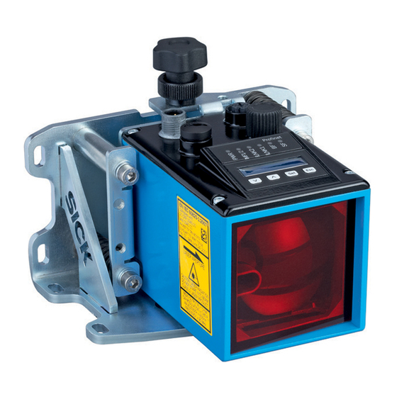
Page 21: Setup And Function
Device zero point Optical axis sender Optical axis receiver Bore for knurled screw of the optional alignment bracket Holder for optional alignment bracket Electrical connection Display and operating unit 8015416/ZPN2/2017-09-08 • © SICK AG • Subject to change without notice... -
Page 22: Function
The sender emits the laser beam. The receiver receives light reflected by the reflector. The evaluation electrical unit deter- mines the distance between sensor and reflector by time of flight measure- ment. For measurement, either the reflector or the measuring device may move linearly along the laser beam. The distance measuring device DL100 is equipped with two CANopen ® interfaces and one Ethernet interface. The CANopen interfaces serve ® communication via CANopen . -
Page 23: Display And Operating Elements
• LED on: Output high • LED off: Output low Ethernet • LED off: No Ethernet present • LED green: Ethernet present • LED orange flashing: Data transmission Interface CANopen ® → Status LED, page 119, Table 72. Table 1: LEDs 8015416/ZPN2/2017-09-08 • © SICK AG • Subject to change without notice... -
Page 24: Men Menu
Fig. 6: Measured value display Menu display Menu Fig. 7: Menu display NOTE! If a value or display has more than six characters, the characters are automatically displayed in sequence. © SICK AG • Subject to change without notice • 8015416/ZPN2/2017-09-08... -
Page 25: Transport And Storage
• Initiate complaints. NOTE! Report every defect as soon as you recognize it. Damages claims can only be asserted within the appli- cable complaint periods. 8015416/ZPN2/2017-09-08 • © SICK AG • Subject to change without notice... -
Page 26: Storage
• Storage temperature: –40 to 75 °C • Relative humidity: max. 95 %, non-condensing • At storage exceeding 3 months, regularly inspect the general condition of all components and the packaging. © SICK AG • Subject to change without notice • 8015416/ZPN2/2017-09-08... -
Page 27: Mounting
• To avoid condensation, do not expose the distance measuring device to any quick temperature changes. • Observe the assembly notes for the reflector. → See page 27, chapter 6.2. • Keep sufficient distance to other distance measuring devices. → See page 29, chapter 6.4. • Keep sufficient distance to data transmission photoelectric switches. → See page 31, chapter 6.5. 8015416/ZPN2/2017-09-08 • © SICK AG • Subject to change without notice... -
Page 28: Choose And Mount Reflector
Installing the reflector on highly reflective surfaces Left: Installed in driving axis, installed at the right in the lifting axis Distance measuring device Highly reflective surface Reflector Inclination of approx. 1° to 3° © SICK AG • Subject to change without notice • 8015416/ZPN2/2017-09-08... -
Page 29: Placement Of Multiple Distance Measuring Device
Light beams in the same direction Fig. 9: Placement of two distance measuring devices with light beams in the same light direction Distance measuring device DL100 Reflector Minimum distance Maximum scanning range 8015416/ZPN2/2017-09-08 • © SICK AG • Subject to change without notice... - Page 30 Mounting Light beams in the opposite direction Fig. 10: Placement of two distance measuring devices with light beams in the opposite direction Distance measuring device DL100 Reflector Minimum distance © SICK AG • Subject to change without notice • 8015416/ZPN2/2017-09-08...
-
Page 31: Adjacent Data Transmission Photoelectric Switch
Fig. 11: Placement of the distance measuring device to the data transmission photoelectric switch ISD Distance measuring device DL100 Reflector Data transmission photoelectric switch ISD300, ISD400-1xxx or ISD400-6xxx Minimum distance 8015416/ZPN2/2017-09-08 • © SICK AG • Subject to change without notice... -
Page 32: Align Distance Measuring Device And Reflector Against Each Other
1) For distance measuring devices with a measurement range of 0.15 … 200 m or 0.15 ... 300 m 2) For distance measuring devices with a measurement range of 0.15 … 300 m Table 4: Damping values © SICK AG • Subject to change without notice • 8015416/ZPN2/2017-09-08... -
Page 33: Mount Alignment Bracket And Distance Measuring Device
Fig. 12: Mount alignment bracket Mounting screw M5 Alignment bracket 2. Turn out knurled screw until the distance measuring device can be inserted. 3. Move distance measuring device into the alignment bracket. 8015416/ZPN2/2017-09-08 • © SICK AG • Subject to change without notice... - Page 34 Fig. 13: Mount distance measuring device Knurled screw Alignment bracket Distance measuring device 4. Attach distance measuring device via the knurled screw. Fig. 14: Attach distance measuring device with the knurled screw Knurled screw © SICK AG • Subject to change without notice • 8015416/ZPN2/2017-09-08...
-
Page 35: Distance Measuring Device Above Alignment Bracket
Set screw to align the distance measuring device in X-direction Alignment in Y-direction Fig. 16: Align distance measuring device in Y-direction using the alignment bracket Set screw to align the distance measuring device in Y-direction 8015416/ZPN2/2017-09-08 • © SICK AG • Subject to change without notice... -
Page 36: Electrical Connection
Wiring notes ATTENTION! Fault from improper wiring! Improper wiring may cause malfunctions in operation. Therefore: • Only use shielded cables with twisted pair wires. • Observe wiring notes. © SICK AG • Subject to change without notice • 8015416/ZPN2/2017-09-08... - Page 37 NOTE! → Ready-made cables, see page 134, chapter 15.2. All electrical connections of the distance measuring device DL100 are M12 round plugs. The connection plugs of the distance measuring device are compatible to the SpeedCon™-quick connections and standard-M12 screw connections.
- Page 38 Cables that are sources of interference, such as control cables for inductive loads, motor brakes Cables that are strong sources of interference, such as frequency converter output cables, supply to welding plants; power cables © SICK AG • Subject to change without notice • 8015416/ZPN2/2017-09-08...
-
Page 39: Electrically Connect Distance Measuring Device
2. Connect the measuring device according to the connection diagram. Fig. 21: Position of the electrical connections Plug 1: Supply voltage (Pwr) Socket 2: Ethernet Socket 3: CANopen output ® Plug 4: CANopen input ® 8015416/ZPN2/2017-09-08 • © SICK AG • Subject to change without notice... -
Page 40: Connection Diagrams
Send data signal, not inverted ange white/green Receive data signal, not inverted Tx– orange Send data signal, inverted Rx– green Receive data signal, inverted Table 6: Description socket Ethernet © SICK AG • Subject to change without notice • 8015416/ZPN2/2017-09-08... -
Page 41: Output
+10 … +30 V DC V– black Supply voltage: 0 V CAN_H white CAN bus signal CAN_L blue CAN bus signal Thread Shield Cable shield (housing) Table 8: Description plug CANopen input ® 8015416/ZPN2/2017-09-08 • © SICK AG • Subject to change without notice... -
Page 42: Measured Value Display
• Wait for approx. 2 minutes. The display automatically switches back to measured value display without operation of a key. Any settings made are also saved. © SICK AG • Subject to change without notice • 8015416/ZPN2/2017-09-08... -
Page 43: Change Value
Display of the pending warnings. When an error is pending, the LED PWR flashes red. When no errors are pending, no errors are displayed. → Also see page 122, chapter 12.3, list of possible errors. Table 9: Main menu 8015416/ZPN2/2017-09-08 • © SICK AG • Subject to change without notice... -
Page 44: Menu „Swvers
Main menu → → Menu → → SwVers → → HwVers Push the -key so that the parameter "HwVers" is displayed. Parameter Description HwVers Version number display Table 11: Menu "HwVers" © SICK AG • Subject to change without notice • 8015416/ZPN2/2017-09-08... -
Page 45: Menu „Canopen
Options • 0.1 • 0.125 • 1.0 • 10.0 • 100.0 • ModeDef Factory setting • 0.1 mm Note: ModDef = Module Defined → See page 105, chapter 10.11.4. 8015416/ZPN2/2017-09-08 • © SICK AG • Subject to change without notice... -
Page 46: Menu „More
-key. The currently set option is displayed here. Options Description Yes / Activate and deactivate expanded menu view. Options • Yes • No Factory setting • No Table 13: Menu "More" © SICK AG • Subject to change without notice • 8015416/ZPN2/2017-09-08... -
Page 47: Menu „Mfx On
• Enable: Multifunction input/output MF1 and multifunction output MF2 are activated. • Disable: Multifunction input/output MF1 and multifunction output MF2 are deactivated. Factory setting • Enable Table 14: Menu "MFx On" 8015416/ZPN2/2017-09-08 • © SICK AG • Subject to change without notice... -
Page 48: Menu „Mf1
No further submenu is displayed for the option “LsrOff”. When the multifunction input MF1 is active, the laser is switched off. Count Counts the switching events of the multifunction input/output. The counter is reset by deactivation and activation of the distance measuring device. Table 15: Menu “MF1” © SICK AG • Subject to change without notice • 8015416/ZPN2/2017-09-08... -
Page 49: Submenu „Mf1 – Dist
Set Hysteresis for the switching threshold Table 16: Submenu "MF1 – Dist" active inactive Limit Dist. Hyst Fig. 26: Displaying the function "Dist." Limit Distance-dependent switching threshold Hyst: Switching threshold hysteresis Dist: Measured distance 8015416/ZPN2/2017-09-08 • © SICK AG • Subject to change without notice... -
Page 50: Submenu „Mf1 – Speed
• –: Once the set speed is exceeded with decreasing distance, the switching output is activated. Factory setting • + / – Table 17: Submenu "MF1 – Speed" © SICK AG • Subject to change without notice • 8015416/ZPN2/2017-09-08... -
Page 51: Submenu „Mf1 – Srvice
Possible reasons may be incorrect measure- ments, interruption of the light beam, optical interferences or electrical interferences. Options • On • Off Factory setting • On 8015416/ZPN2/2017-09-08 • © SICK AG • Subject to change without notice... -
Page 52: Position
We recommend performing the "Preset" in standstill or at very low speeds. The maximum activation time is typically at 10000 cycles. © SICK AG • Subject to change without notice • 8015416/ZPN2/2017-09-08... - Page 53 4. Activate the multifunction input MF1, e.g. via a proximity initiator, photo- electric sensor or switch. 5. The output value of the distance measuring device corresponds to the value set for "Preset" at the initialization position. 8015416/ZPN2/2017-09-08 • © SICK AG • Subject to change without notice...
-
Page 54: Menu „Mf2
→ Also see page 50, Table 17. Submenu "MF2 – Srvice" This submenu corresponds to the submenu "Srvice" in the menu "MF1". → Also see page 52, Table 18. © SICK AG • Subject to change without notice • 8015416/ZPN2/2017-09-08... -
Page 55: Menu „Offset
• Menu “more”: Option “Yes” Parameter Description AvgDst Select filter depth for the distance values. Options • Medium • Slow • Fast Factory setting • Medium Note: Medium and Fast use the same averaging depth. 8015416/ZPN2/2017-09-08 • © SICK AG • Subject to change without notice... - Page 56 • Mode 1 • Mode 2 • Mode 3 • Mode 4 Factory setting • Mode 1 Perform reset → see page 57, chapter 8.6. Reset Table 22: Menu “SpecFu” © SICK AG • Subject to change without notice • 8015416/ZPN2/2017-09-08...
-
Page 57: Perform Reset
2. Push the key 3. The safety request "Sure?" is displayed. 4. Push the button to reset the measuring device to the delivery state. Push the key to cancel the process. 8015416/ZPN2/2017-09-08 • © SICK AG • Subject to change without notice... -
Page 58: Ip-Network Configuration
• The DHCP server has an interference. • The DHCP server was not yet ready when the distance measuring device was switched on. • The network connection has an interference. © SICK AG • Subject to change without notice • 8015416/ZPN2/2017-09-08... -
Page 59: Device Information
Page "Device information" – field "Software version" Field "Hardware Version" Parameter Description Hardware Displaying the hardware version Version Read/Write access • Read only Table 26: Page "Device information" – field "Hardware version" 8015416/ZPN2/2017-09-08 • © SICK AG • Subject to change without notice... -
Page 60: User Information
You may only enter user information at the user level "Mainte- nance". This requires the password "esick". Read/Write access • Write only Table 29: Page "User information" – field "Store user information" © SICK AG • Subject to change without notice • 8015416/ZPN2/2017-09-08... -
Page 61: Measurement Values
Read/Write access • Read only Unit • m/s Acceleration Measurement value "Acceleration" Read/Write access • Read only Unit • m/s2 Table 31: Page "Measured data" – field "Measurement values" 8015416/ZPN2/2017-09-08 • © SICK AG • Subject to change without notice... -
Page 62: Diagnostic Data
Display of current internal device temperature Read/Write access • Read only Unit • °C Operating hours Display of current operating hours Read/Write access • Read only Unit • h Table 32: Page “Diagnostic data” © SICK AG • Subject to change without notice • 8015416/ZPN2/2017-09-08... -
Page 63: Parameter Settings
Specify present value for the distance measurement value. Read/Write access • Read and write Input value • –300000 ... 300000 Unit • mm Factory setting • 0 Table 33: Page "Parameter settings" – field "General settings" 8015416/ZPN2/2017-09-08 • © SICK AG • Subject to change without notice... - Page 64 Activate and deactivate multifunction input and output MF1 and multifunction output MF2. Read/Write access • Read and write Input value • 0: off / 1: on Factory setting • On Table 35: Page "Parameter settings" – field "MF1/MF2 activation" © SICK AG • Subject to change without notice • 8015416/ZPN2/2017-09-08...
- Page 65 MF1. Read/Write access • Read and write Input value • 0: high / 1: low Factory setting • Low Table 36: Page “Parameter settings” – field “MF1 Function configuration” 8015416/ZPN2/2017-09-08 • © SICK AG • Subject to change without notice...
- Page 66 Threshold Enter switching threshold for the multifunction output MF1. velocity Read/Write access • Read and write Input value • 0 ... 15000 Unit • mm/s Factory setting • 5000 © SICK AG • Subject to change without notice • 8015416/ZPN2/2017-09-08...
- Page 67 • The warning messages "Measurement stability", "Level", "Laser", "Temperature" and "Device not ready" are activated. The message "Heater state" is deactivated. Table 39: Page "Parameter settings" – field "MF1, Service configuration" 8015416/ZPN2/2017-09-08 • © SICK AG • Subject to change without notice...
- Page 68 You may reset the counters via the button "Reset MF2". Read/Write access • Read and write Input value • –2147483648 ... 2147483647 Table 41: Page "Parameter settings" – field "Number MF activation" © SICK AG • Subject to change without notice • 8015416/ZPN2/2017-09-08...
- Page 69 Enter power up threshold for heating. Read/Write access • Read and write Input value • –10 ... +40 Unit • °C Factory setting • –10 Table 43: Page "Parameter settings" – field "Heater" 8015416/ZPN2/2017-09-08 • © SICK AG • Subject to change without notice...
- Page 70 Click the button "Parameter Reset" to reset the parameters to Reset factory settings. Read/Write access • Write only Table 46: Page "Parameter settings" – field "Set parameters to default values" © SICK AG • Subject to change without notice • 8015416/ZPN2/2017-09-08...
-
Page 71: Methods
• Use the selection button to select the desired option. • Click the button to perform the option. Read/Write access • Write only Input value • 0: Off / 1: On / 2: Auto Factory setting • Auto Table 47: Page "Methods" 8015416/ZPN2/2017-09-08 • © SICK AG • Subject to change without notice... -
Page 72: Canopen ® -Interface
MSEF, it is 0. Communication Object Identifier: Each communications object has a unique COB-ID in the network. It serves addressing and priorisation of the PDOs. The lower the COB-ID, the higher the priority. © SICK AG • Subject to change without notice • 8015416/ZPN2/2017-09-08... -
Page 73: Topology
74, Table 49. A final resistor (terminator) of 120 Ohm must be connected to the ends of the bus line (trunk line). Terminator Trunk Line Master Drop Line Terminator Terminator Fig. 27: CANopen topology (example) ® 8015416/ZPN2/2017-09-08 • © SICK AG • Subject to change without notice... -
Page 74: Drop Lines
→ For the entire menu structure, see page 137, chapter 16. 10.3.2 Setting the Node-ID via SOPAS ET 1. Select the parameter page in the menu tree. A dialog window is opened in the main widow. 2. Enter the Node-ID in grouping CANopen configuration. © SICK AG • Subject to change without notice • 8015416/ZPN2/2017-09-08... -
Page 75: Setting The Node-Id Via Lss
LSS network into con- figuration mode. Slave – – – – – – – – – – Note: There is no feed- back from the slave. Table 50: Input via LSS 8015416/ZPN2/2017-09-08 • © SICK AG • Subject to change without notice... -
Page 76: Baud Rate Setting
→ For the entire menu structure, see page 137, chapter 16. 10.4.2 Setting the baud rate via SOPAS ET 1. Select the parameter page in the menu tree. A dialog window is opened in the main widow. 2. Enter the Baud rate in grouping CANopen configuration. © SICK AG • Subject to change without notice • 8015416/ZPN2/2017-09-08... -
Page 77: Setting The Baud Rate Via Lss
Slave – – – – – – – – – – Note: There is no feed- back from the slave. Table 51: Enter baud rate via LSS 8015416/ZPN2/2017-09-08 • © SICK AG • Subject to change without notice... -
Page 78: Communication Profile Cia 301
® dressed via an index. The object directory is structured in three different parts: • Communications segment • Manufacturer specific segment • Device-specific segment 10.5.4 EDS file You can download the EDS file online from “www.sick.com/dl100“. © SICK AG • Subject to change without notice • 8015416/ZPN2/2017-09-08... -
Page 79: Telegram Setup
29-bit CAN-ID 29-bit CAN-ID of the expanded CAN frame (CAN-specification 2.0 B) 11-bit CAN-ID 11-bit CAN-ID of the CAN basis frame (CAN-specification 2.0 A) Table 54: Description of the individual bits within the COB-ID 8015416/ZPN2/2017-09-08 • © SICK AG • Subject to change without notice... -
Page 80: Setup 11-Bit Can-Id
Example for SYNC object with The SYNC object has the value 80h as identifier. The value for the Node-ID NODE-ID 6 is added to the identifier. This leads to a CAN-ID with the value 86h, which is made up as follows: • Function code: 0001b • Node-ID: 0000110b 11-bit CAN-ID Function code Node-ID Fig. 30: Example SYNC object © SICK AG • Subject to change without notice • 8015416/ZPN2/2017-09-08... -
Page 81: Identifier Priority
Global fail safe command 2 – 112 2h – 70h Not assigned 00001110001 NMT master node–ID [Net- work redundancy] (Tx)/Active Master detection and NMT flying master negotiation (Rx) 00001110010 NMT flying master negotia- tion (Tx) 00001110011 Active NMT master detection (Tx) 8015416/ZPN2/2017-09-08 • © SICK AG • Subject to change without notice... - Page 82 Not assigned 1110xxxxxxx 1793 – 1919 701h – 77Fh NMT Error-Control 1920 – 2019 780h – 7E3h Not assigned 11111100100 2020 7E4h LSS (Tx) 11111100101 2021 7E5h LSS (Rx) © SICK AG • Subject to change without notice • 8015416/ZPN2/2017-09-08...
-
Page 83: Pdo And Sdo
The PDOs corresponds to a CAN telegram each and are assigned via its specific CAN identifier and determined in their priority. A difference is made between receive PDOs (RPDOs) and transmit PDOs (TP- DOs). The designation is applied from the device’s point of view. The DL100 does not contain any RPDOs. A server SDO object provides a service for parameterizing of object direc- tory entries. - Page 84 The hexadecimal display of the index and data D0 to D3 will take place in reverse order within the respective byte. example: Index 6004h is illustrated as 04h | 60h. © SICK AG • Subject to change without notice • 8015416/ZPN2/2017-09-08...
-
Page 85: Communication
Node-ID 6 in Operational Mode Slave – – – – – – – – – No response Table 60: Example NMT command: Set NMT of node 6 to Operational Mode 8015416/ZPN2/2017-09-08 • © SICK AG • Subject to change without notice... -
Page 86: Synchronous And Asynchronous Pdos
If the “Event Timer” is 5, the PDO1 is sent every 5 ms. 10.7.3 Transmission Type The “Transmission Type” specifies how dispatch of the PDO is triggered and how received PDOs are treated. A difference is made between TPDOs (transmit PDOs) and RPDOs (receive PDOs) The designation is applied from the device’s point of view. The DL100 does not contain any RPDOs. © SICK AG • Subject to change without notice • 8015416/ZPN2/2017-09-08... - Page 87 For an RTR and event-driven data transfer, the CANopen device starts when receiving a SYNX query. The PDO is transferred at once. Event driven For an event-driven data transmission, the PDO may be transferred based on an internal event in the CANopen device. The definition of events is not contained in the specification. Events may be specified in device profiles and application profiles. 8015416/ZPN2/2017-09-08 • © SICK AG • Subject to change without notice...
- Page 88 TPDO Time Samples taken immediately Samples taken immediately at reception of the at reception of the SYNC objects. SYNC objects. Fig. 32: Bus synchronization and data determination © SICK AG • Subject to change without notice • 8015416/ZPN2/2017-09-08...
-
Page 89: Emergency Messages (Emcy Messages)
2) The heartbeat event is reset by: A new heartbeat producer has been received. Object 1016h has been newly written. Table 62: Overview of general EMCY messages Other supported CAN-internal EMCY-messages: • CAN overrun (objects lost): 8110h • CAN in error passive mode: 8120h • Restored by “Bus off”: 8140h 8015416/ZPN2/2017-09-08 • © SICK AG • Subject to change without notice... -
Page 90: Overview Of Manufacturer-Specific Emcy Massages
A communications error (Overrun EEC 0x8110, Error state EEC 0x8120) remains in the error register (object 1001h) (bit 0 and bit 4 set) until the command “Communication Reset” or “Application Reset” was performed. © SICK AG • Subject to change without notice • 8015416/ZPN2/2017-09-08... -
Page 91: Overview Object Directory
Operating instructions Distance measuring device DL100 – CANopen® CANopen®-interface 10.9 Overview Object directory The objects listed in the tables are supported by the DL100. Notice for the objects 1800h, 1804h and 1805h: The object “Compat- ibility Entry” is not located in the EDS file. The object “Number of Entries” remains at 6 entries, however. - Page 92 384d + NodeID, 180h + NodeID Transmission Type Unsigned8 255d, 255d, Inhibit Time Unsigned16 rw 65535d, FFFFh Compatibility Entry Unsigned8 – – Event Timer Unsigned16 rw 65535d, FFFFh Sync Start Value Unsigned8 255d, © SICK AG • Subject to change without notice • 8015416/ZPN2/2017-09-08...
- Page 93 Mapping Entry 1 Unsigned32 ro – – 1610874912d, 60040020h [1A01h] Transmit1 PDO Map- ping Parameter 2 Number of Entries Unsigned8 – – Mapping Entry 1 Unsigned32 ro – – 1610874912d 60040020h 8015416/ZPN2/2017-09-08 • © SICK AG • Subject to change without notice...
- Page 94 DL100 – DL100 + 300 m 300 m [2001h] Velocity Integer32 –10 m/s 10 m/s [2002h] Time Stamp Unsigned32 ro [2003h] Level Integer16 [2004h] Warnings Unsigned8 [2005h] Errors Unsigned8 © SICK AG • Subject to change without notice • 8015416/ZPN2/2017-09-08...
- Page 95 Unsigned16 rw –1 [6500h] Operating Status Unsigned16 ro [6501h] Single-turn Resolution Unsigned32 ro 100000 100000000 100000 and Measuring Step [6502h] Number of Distin- Unsigned16 ro – – guishable Revolutions 8015416/ZPN2/2017-09-08 • © SICK AG • Subject to change without notice...
- Page 96 Integer32 – – Profile specific mal Position Value Manufacturer Maxi- Integer32 – – Profile specific mal Position Value [650Bh] Serial Number Unsigned32 ro – 99999999d, 5F5E0FFh Table 64: Overview object directory © SICK AG • Subject to change without notice • 8015416/ZPN2/2017-09-08...
-
Page 97: Communications Segment
Subindex 0 contains the current error status. Writing the value 0 to subindex 0 completely deletes the error history. Subindex Name Description Number of Entries 1h – 5h Standard Error Field 1 – 5 8015416/ZPN2/2017-09-08 • © SICK AG • Subject to change without notice... -
Page 98: Object 1005H Cob-Id Sync
All values in the object directory (communications segment, manufacturer- specific segment and profile segment) are set to default values. The default values are saved automatically. The Node-ID and baud rate are ex- cluded and contain their current value. © SICK AG • Subject to change without notice • 8015416/ZPN2/2017-09-08... -
Page 99: Object 1014H Cob-Id Emcy
The following functions are possible: • 00h: Bootup • 04h: Stopped • 05h: Operational • 7Fh: Pre-Operational 8015416/ZPN2/2017-09-08 • © SICK AG • Subject to change without notice... -
Page 100: Object 1018H Identity Object
Description The SYNC message should be transmitted as a CAN message with the data length “0”. Reserve 2 – 240 The SYNC message should be transmitted as a CAN message with a data length “1”. The first data byte contains the counter. 241 – 255 Reserve © SICK AG • Subject to change without notice • 8015416/ZPN2/2017-09-08... -
Page 101: Object 1029H Error Behaviour
The object describes the SDO server object. It provides the SDO communi- cation. Subindex Name Description Number of Entries Indication of the number of subindices within object 1200h. COB-ID Client > Server COB-ID Server > Client 8015416/ZPN2/2017-09-08 • © SICK AG • Subject to change without notice... -
Page 102: Object 1800H Transmit Pdo Communication Parameter 1
Number of Entries = 0), the SDO-Abort-message “08000022h” is generated. Ac- cording to the specification CiA 301 (Version 4.2, page 36, length of the process data at least 1) it is not permitted for TPDOs that have no mapping entries to be sent. Transmission Type Defines the transmission type. © SICK AG • Subject to change without notice • 8015416/ZPN2/2017-09-08... -
Page 103: Object 1805H Transmit Pdo Communication Parameter 6
10.14 “Dynamic Mapping”. 10.10.21 Object 1A00h Transmit PDO Mapping Parameter 1 Subindex Name Description Number of Entries Indication of the number of subindices within object 1A00h. Mapping Entry 1 Mapping fix. 8015416/ZPN2/2017-09-08 • © SICK AG • Subject to change without notice... -
Page 104: Object 1A02H Transmit Pdo Mapping Parameter 2
10.11.1 Object 2000h Distance The object 2000h issues the current distance value in the selected resolu- tion. The resolution can be selected in object 4000h or 6005h subindex 01h. © SICK AG • Subject to change without notice • 8015416/ZPN2/2017-09-08... -
Page 105: Object 2001H Velocity
If the value is equal to 4, the resolution is only possible via object 6005h, Subindex 2, “Linear Encoder Measuring Step Setting”. If the value is un- equal 4, object 6005h is ignored. 8015416/ZPN2/2017-09-08 • © SICK AG • Subject to change without notice... -
Page 106: Object 4002H Device Product Code
• Value: 02h: Laser on • Value: 03h: Reset preset (preset = offset = 0), deletes a present preset • Value: 04h...FFh: Reserve 10.11.11 Object 4007h Reset Preset Performs a cold start so that the preset on the CPR is not activated event- triggered. © SICK AG • Subject to change without notice • 8015416/ZPN2/2017-09-08... -
Page 107: Device Profile Cia 406 (Absolute Linear Encoder)
6001h (Measuring Units per Revolution), 6002h (Total Measuring Range in Measuring Units) and 600Ah (High Resolution Total Measuring Range in Measuring Units). The DL100 supports only 6002h. If “Sfc” is deactivated (value = 0), the above object settings are ignored. Object 6001h is comparable to object 4000h. -
Page 108: Object 6001H Measuring Units Per Revolution
• Input = 7. The total measuring route is structured in 7 sections. • 100 m/7 = 14.2857 m. One section is therefore 14.2857 m. If the 14.2857 m are overrun, the measured value starts again at 0. © SICK AG • Subject to change without notice • 8015416/ZPN2/2017-09-08... -
Page 109: Object 6003H Preset Value
300000 mm. If input of the preset is equal to 0, the current distance is set to zero (Distance = –Distance offset mess Setting a preset value automatically updates the object 6509h (Offset Value). The value range of the preset is ± +300.000 mm. Negative values are not permitted according to specification CiA 406. The data type of the 6003h object is unsigned32. 8015416/ZPN2/2017-09-08 • © SICK AG • Subject to change without notice... -
Page 110: Object 6004H Position Value
Position Measuring Step The indication as a multiple of 1 nm. • Smallest resolution (default): 1/10 mm => 0.1 mm / 1 nm = 100000 • Highest resolution: 100 mm => 100 mm / 1nm = 100000000 Speed Measuring Steps The indication as a multiple of 0.01 mm/s • Smallest resolution (default): 1/10 mm/s => 0.1 mm/s / 0.01 mm/s = 10 • Highest resolution: 100 mm/s => 100 mm/s / 0.01 mm/s = 10000 © SICK AG • Subject to change without notice • 8015416/ZPN2/2017-09-08... -
Page 111: Devices
Is a copy of 6000h. 10.12.12 Object 6501h Single-turn Resolution and Measuring Step Indication of the resolution as a multiple of 1 nm. E.g. a resolution of 1 mm corresponds to 1000000. 8015416/ZPN2/2017-09-08 • © SICK AG • Subject to change without notice... -
Page 112: Object 6502H Number Of Distinguishable Revolutions
Operating instructions Distance measuring device DL100 – CANopen® CANopen®-interface 10.12.13 Object 6502h Number of Distinguishable Revolutions For linear encoders, i.e. also for the DL100, this value is always “1”. 10.12.14 Object 6503h Alarms The object shows pending alarms. Function Plausibility error 1 …... -
Page 113: Object 6505H Warnings
10.12.18 Object 6507h Profile and Software Version Byte 3-2: Application controller version byte 1-0: 406 Encoder Profile Ver- sion. The currently published version of the encoder profile 406 of the CiA is 3.2.0. The current status of a “work draft” is illustrated by the third digit. If the third digit is 0, it is a published version. 8015416/ZPN2/2017-09-08 • © SICK AG • Subject to change without notice... -
Page 114: Object 6508H Operating Time
0. Index 1 contains the minimum distance value. Index 2 of the maximum distance value. The following min/max values apply: • Profile 1: –100 m / +100 m • Profile 2: –200 m / +200 m • Profile 3: –300 m / +300 m 10.12.22 Object 650Bh Serial Number Contains the 8-digit serial number. © SICK AG • Subject to change without notice • 8015416/ZPN2/2017-09-08... -
Page 115: Parameterize Linear Absolute Value Encoders
Manufacturer-specific 406 (Encoder) Profile (SICK) Profile TPDO 1 TPDO 2 TPDO 5 TPDO 6 TPDO 4 TPDO 3 frei TPDO1 to TPDO4 are in the pre-defined number circle (181h to 57Fh) TPDO1 and TPDO2 are CiA 406-specific. TPDO5 and TPDO6 are manufac- turer-specific and deactivated by default (COB-ID 0x80000000). The pre-defined PDO range must be used. Assignment to CAN-IDs usually happens by a bus designer using a configuration software that assumes correct assignment of CAN-IDs. The following configurations are recommended. 8015416/ZPN2/2017-09-08 • © SICK AG • Subject to change without notice... - Page 116 If there are, e.g., 20 participants with the Node-IDs 1 to 20, the TPDO5 can be mapped to the free number circle of TPDO1. For this, the Node-ID of the DL100 must be set to 21 (15h) and the COB-ID of the TPDO5 to 195h (180h+15h=195h).
- Page 117 2022 (7E6h) – 2047 (7FFh) Reserved Table 69: Version 4 for configuration DL100 Example It should be configured in TPDO with the following properties • TPDO should be active • TPDO should support RTR • TPDO uses 11-bit CAN-ID. 8015416/ZPN2/2017-09-08 • © SICK AG • Subject to change without notice...
- Page 118 Position Value Unsigned32 0x6004 00 20 6030h Speed Value Channel 1 Integer16 0x6030 01 10 6503h Alarms Unsigned16 0x6503 00 10 6505h Warnings Unsigned16 0x6505 00 10 Table 70: © SICK AG • Subject to change without notice • 8015416/ZPN2/2017-09-08...
-
Page 119: Status Led
2 in subin- dex 0. 10.15 Status LED The DL100 uses a red/green bicolor LED to display the bus status and the Network State Machine. In case of conflict, red dominates. The following conditions are supported:... -
Page 120: Cleaning And Maintenance
Cleaning intervals Cleaning housing Skilled person depending on ambience conditions and climate Every 6 months Check screw and plug connections at regular intervals. Skilled person Table 73: Maintenance plan © SICK AG • Subject to change without notice • 8015416/ZPN2/2017-09-08... -
Page 121: Troubleshooting
LED PWR flashes red. An error is pending. see page 122, chapter 12.3. → See page 119, Table 72. → See page 119, Table 72. LED STA Table 74: LED status display 8015416/ZPN2/2017-09-08 • © SICK AG • Subject to change without notice... -
Page 122: Error Messages
• Re-align distance measuring device and reflector. → For alignment and mounting, see page 27, chapter 6. eLaser The service life of a measurement laser is Interchange measuring device. exceeded. © SICK AG • Subject to change without notice • 8015416/ZPN2/2017-09-08... -
Page 123: Return
Observe the following items for disposal: • The distance measuring device must not be disposed of in the house- hold waste. • Dispose of the distance measuring device according to the respective country-specific provisions. 8015416/ZPN2/2017-09-08 • © SICK AG • Subject to change without notice... -
Page 124: Technical Data
14 Technical data NOTE! You may download, save and print the online data sheet with technical data, dimensions and connection diagrams for your distance measuring device online at "www.sick.com/dl100". © SICK AG • Subject to change without notice • 8015416/ZPN2/2017-09-08... -
Page 125: Dimensions
All dimensions in mm (inch) Fig. 33: Dimensions distance measuring device DL100 Optical axis sender Optical axis receiver Device zero point Threaded mounting hole M5 LED "Status" Display Operating elements 8015416/ZPN2/2017-09-08 • © SICK AG • Subject to change without notice... -
Page 126: Laser/Optics
2 pursuant to EN 60825-1 /CDRH CW modulation ± 0.85 Po sine-shape modulated Maximum output ≤ 1.9 mW Pulse duration 6.8 ns Wave length 655 nm Frequency ≥ 90 MHz Light spot dimensions Typical 5 mm + (2 mm x distance [m]) Average service life Typical 100 000 h at +25 °C Table 78: Laser/Optics © SICK AG • Subject to change without notice • 8015416/ZPN2/2017-09-08... -
Page 127: Performance
Multifunction input MF1, adjustable • Hi > 12 V • Lo < 3 V → See page 48, Table 15, parameter “ActSta”. Protective circuit No, not reverse polarity protected Table 81: Inputs 8015416/ZPN2/2017-09-08 • © SICK AG • Subject to change without notice... -
Page 128: Ambient Conditions
10 m/s² Vibration resistance (sine) EN 60068-2-6 Noise EN 60068-2-64 Shock resistance EN 60086-2-27 1) When used in the household area, the device may cause interferences. Table 84: Ambient conditions © SICK AG • Subject to change without notice • 8015416/ZPN2/2017-09-08... -
Page 129: Constructive Setup
• Casing: Cast aluminium GD-AlSi12Cu1 (3.2982.05) • Front screen: PMMA Connections M12, SpeedCon™ Display • 6 points with a 5 x 7 point matrix • Overflow is displayed with the maximum value that can be displayed, –99999 bzw. 999999. Table 85: Constructive setup 8015416/ZPN2/2017-09-08 • © SICK AG • Subject to change without notice... -
Page 130: Accessories
Complete details on all accessories are available at “www.sick.com/dl100”. 15.1 Reflectors and reflective tape 15.1.1 Reflectors Fig. 34: Reflector 0.3 x 0.3 m² Diamond Grade, mounted Description Reflector 0.3 x 0.3 m² Diamond Grade, mounted on base plate ALMG3 Type PL240DG Part no. 1017910 © SICK AG • Subject to change without notice • 8015416/ZPN2/2017-09-08... - Page 131 Fig. 35: Reflector 0.6 x 0.6 m² Diamond Grade, mounted Description Reflector 0.6 x 0.6 m² Diamond Grade, mounted on base plate ALMG3 Type PL560DG Part no. 1016806 Fig. 36: Reflector 1.0 x 1.0 m² Diamond Grade, mounted Description Reflector 1.0 x 1.0 m² Diamond Grade, mounted on base plate ALMG3 Type PL880DG Part no. 1018975 8015416/ZPN2/2017-09-08 • © SICK AG • Subject to change without notice...
- Page 132 Silicon wire 2 m, 3 x 0.75 mm , open ending Fig. 38: Reflector 0.6 x 0.6 m² Diamond Grade, mounted, including heating Description Reflector 0.6 x 0.6 m² Diamond Grade, mounted, on base plate ALMG3, including controlled heating +20 °C, 230 V AC, 200 W, IP 64 Type PL560DG-H Part no. 1023888 © SICK AG • Subject to change without notice • 8015416/ZPN2/2017-09-08...
-
Page 133: Reflective Tape
Operating instructions Distance measuring device DL100 – CANopen® Accessories 15.1.2 Reflective tape Fig. 39: "Diamond grade" reflective tape Description "Diamond grade" reflective tape, size customizable Type REF-DG Part no. 4019634 Description "Diamond grade" reflective tape, curve 749 x 914 mm2 Type REF-DG Part no. 5320565 8015416/ZPN2/2017-09-08 • © SICK AG • Subject to change without notice... -
Page 134: Connection Systems
Cable plug, M12, 5-pin, straight, terminator, DeviceNet and CANopen ® Type STE-1205-GKEND Part no. 6037193 15.2.4 Connection cables Description Connection cable, M12, 5-pin, plug straight/socket straight, 5 m, CAN/CANopen , shielded ® Type DSL-1205-G05MK Part no. 6021168 © SICK AG • Subject to change without notice • 8015416/ZPN2/2017-09-08... -
Page 135: Mounting Systems
BEF-AH-DX100 Part no. 2058653 Material: Zinc-plated steel sheet 15.3.2 Deflector mirror for mounting at alignment bracket Description Deflector mirror for deflecting the light beam by 90°. Can only be mounted at alignment bracket BEF-AH-DX100. Type BEF-BEF-DX100 Part no. 2068395 Material: Zinc-plated steel sheet 8015416/ZPN2/2017-09-08 • © SICK AG • Subject to change without notice... -
Page 136: Other Accessories
Description Cooling casing Type TPCC-Dx100 Part no. 6048328 Material Glass-fiber reinforced plastic (GFK) Operating ambience temperature –20 … +75 °C (short-term +80 °C) Supply voltage 24 V DC ± 20 % Current consumption 15 A at 24 V DC Enclosure rating IP 54 © SICK AG • Subject to change without notice • 8015416/ZPN2/2017-09-08... -
Page 137: Menu Structure
Dist Speed Srvice LsrOff Preset Choose option nur Anzeige Menu depending on selection Functn ActSta Functn Count Dist Speed Srvice Choose option Display only * * Display as ticker 8015416/ZPN2/2017-09-08 • © SICK AG • Subject to change without notice... - Page 138 Choose option Choose option Enter value Enter value Enter value Srvice WrnLsr WrnLvl WrnTemp WrnPlb NotRdy Heat Choose option Choose option Choose option Choose option Choose option Choose option © SICK AG • Subject to change without notice • 8015416/ZPN2/2017-09-08...
- Page 139 Error messages ............122 CiA 406 ................78 Ethernet ................. 58 Cleaning ............... 120 Explanation of terms COB (Communication Object Identifier) ....... 72 CANopen® ............... 72 COB-ID ................79 Communication profile CiA 301 ........78 8015416/ZPN2/2017-09-08 • © SICK AG • Subject to change without notice...
-
Page 140: Index
Setting via display ............ 74 6200h Cyclic Timer ..........111 Setting via LSS ............75 6500h Operating Status ........111 Setting via SOPAS ET ..........74 Non-intended use ............16 © SICK AG • Subject to change without notice • 8015416/ZPN2/2017-09-08... - Page 141 Store parameter ............70 Preset Store user information ..........60 CANopen® ............. 109 User information ............60 Description ............... 52 Status indicator Display via LED STA ..........119 Status indicators ............23 8015416/ZPN2/2017-09-08 • © SICK AG • Subject to change without notice...
- Page 142 Transport ................ 25 Transport inspection ............. 25 Troubleshooting ............121 Type code ..............126 Type label ............... 20 UL safety notes .............. 11 Warning messages ............122 Wiring notes ..............36 © SICK AG • Subject to change without notice • 8015416/ZPN2/2017-09-08...
- Page 143 Operating instructions Distance measuring device DL100 – CANopen® 8015416/ZPN2/2017-09-08 • © SICK AG • Subject to change without notice...
- Page 144 Phone +852 2153 6300 Phone +421 482 901201 E-Mail ghk@sick.com.hk E-Mail mail@sick-sk.sk Hungary Slovenia Phone +36 1 371 2680 Phone +386 591 788 49 E-Mail office@sick.hu E-Mail office@sick.si India South Africa Phone +91 22 6119 8900 Phone +27 11 472 3733 Further locations at www.sick.com E-Mail info@sick-india.com E-Mail info@sickautomation.co.za SICK AG | Waldkirch | Germany | www.sick.com...
Need help?
Do you have a question about the DL100 and is the answer not in the manual?
Questions and answers