SICK DUSTHUNTER T Operating Instructions Manual
Dust concentration monitor
Hide thumbs
Also See for DUSTHUNTER T:
- Operating instructions manual (142 pages) ,
- Operating instructions manual (261 pages)
Table of Contents
Advertisement
Quick Links
Kalsel-1 2 X 100MW Coal Fired Power Plant
Document Number
Document
Document Title
Information
Category
Comment note.
Contractor's Transmittal No.
Employer's Transmittal No.
Reference
No.
1
Rev.1
DOCUMENT REPLY SHEETS
IFI
KSL1-HEC-TPI-V2982
KSL1-TPI-T6067
Employer's Comment
KSL1L-HNE-CEMG-05-003
O&M Manual for CEMS
Discipline
Rev. No.
Return status
Contractor's reply
Manual for DAHS (Data Acquisition Software) is added.
<Return Status>
A : Approved
AC : Approved except as Noted
RC : Return for Correction
X : Rejection
I
: Received for Information
IC : Received for Information and
CI
Returned With Comments
1
Issue date
I
Issue date
5-Feb-18
14-Feb-18
Employer's comment
applied to next
Revision (Y/N)
-
Advertisement
Chapters
Table of Contents
Troubleshooting

Related Manuals for SICK DUSTHUNTER T


Summary of Contents for SICK DUSTHUNTER T
- Page 1 DOCUMENT REPLY SHEETS Kalsel-1 2 X 100MW Coal Fired Power Plant <Return Status> Document Number KSL1L-HNE-CEMG-05-003 A : Approved AC : Approved except as Noted Document RC : Return for Correction Document Title O&M Manual for CEMS Information X : Rejection : Received for Information IC : Received for Information and Category...
- Page 2 Reviewed by HEC before submission to TPI (Engineer : J.H.Bae, I&C) For Information ’18.06.18 Issued For Information S.H.KIM S.B.LEE S.Y.SUNG ’17.01.23 Issued For Information S.H.KIM S.B.LEE S.Y.SUNG ’16.12.02 Issued For Information S.H.KIM S.B.LEE S.Y.SUNG REV. DATE DESCRIPTION PRPD CHKD APPD OWNER : PROJECT : KALSEL-1 COAL FIRED POWER PLANT PROJECT...
- Page 3 TABLE OF CONTENTS 1.0 DUST HUNTER T100 2.0 GMS800 3.0 FLOWSIC100 4.0 DEW POINT (GM-35) 5.0 TEMP. TRANSMITTER 6.0 DATA LOGGER 7.0 DAHS...
- Page 4 O P E R A T I N G I N S T R U C T I O N S 1.0 DUST HUNTER T100 DUSTHUNTER T Dust Concentration Monitor Description Installation Operation...
- Page 5 Guarantee Information Specified product characteristics and technical data do not serve as guarantee declarations. © SICK MAIHAK GmbH. All rights reserved. DUSTHUNTER T · Operating Instructions · 8012428 V2.0 · © SICK MAIHAK GmbH...
- Page 6 NOTICE Hazard which could result in property damage. Information Symbols Important technical information for this product Supplementary information Link to information at another place DUSTHUNTER T · Operating Instructions · 8012428 V 2.0 · © SICK MAIHAK GmbH...
-
Page 7: Table Of Contents
Online help............. . . 56 DUSTHUNTER T · Operation Instructions · 8012428 V 2.0 · © SICK MAIHAK GmbH... - Page 8 Technical Data ............. 108 DUSTHUNTER T · Operation Instructions · 8012428 V 2.0 · © SICK MAIHAK GmbH...
- Page 9 Password..............122 DUSTHUNTER T · Operation Instructions · 8012428 V 2.0 · © SICK MAIHAK GmbH...
-
Page 10: Important Information
Important Information DUSTHUNTER T Important Information Main hazards Intended use Responsibility of user DUSTHUNTER T · Operating Instructions · 8012428 V 2.0 · © SICK MAIHAK GmbH Germany... -
Page 11: Main Hazards
Disconnect mains lines before working on mains connections or parts carrying mains voltage. Refit any contact protection removed before switching the mains voltage back on again. DUSTHUNTER T · Operating Instructions · 8012428 V 2.0 · © SICK MAIHAK GmbH Germany... -
Page 12: Intended Use
– the device could become dangerous – the manufacturer’s warranty becomes void Restrictions of use ⊗ The DUSTHUNTER T measuring system is not approved for use in potentially explosive atmospheres. DUSTHUNTER T · Operating Instructions · 8012428 V 2.0 · © SICK MAIHAK GmbH Germany... -
Page 13: Responsibility Of User
Optical subassemblies are removed from the duct if the purge air supply fails and the duct opening is closed off (e.g. with a flange cover) DUSTHUNTER T · Operating Instructions · 8012428 V 2.0 · © SICK MAIHAK GmbH Germany... - Page 14 (e.g. when used for measurement and control purposes) The malfunctioning equipment is switched off immediately in case of doubt and that switching off does not cause collateral malfunctions. DUSTHUNTER T · Operating Instructions · 8012428 V 2.0 · © SICK MAIHAK GmbH Germany...
- Page 15 Important Information DUSTHUNTER T · Operating Instructions · 8012428 V 2.0 · © SICK MAIHAK GmbH Germany...
-
Page 16: Product Description
Product Description DUSTHUNTER T Product Description Measuring principle, measured variables Device components Device features and configuration DUSTHUNTER T · Operating Instructions · 8012428 V 2.0 · © SICK MAIHAK GmbH Germany... -
Page 17: Measuring Principle, Measured Variables
The relative opacity is the opacity related to the stack diameter at the end of the stack. Transmission and opacity are usually specified in % Extinction: E = log DUSTHUNTER T · Operating Instructions · 8012428 V 2.0 · © SICK MAIHAK GmbH Germany... -
Page 18: Response Time
Figure 2 Response time Measured value in % 90% of the signal peak Measured value with response time Process change Response time t in s DUSTHUNTER T · Operating Instructions · 8012428 V 2.0 · © SICK MAIHAK GmbH Germany... -
Page 19: Function Check
Changes to the interval time are first effective after the next start ● timepoint. DUSTHUNTER T · Operating Instructions · 8012428 V 2.0 · © SICK MAIHAK GmbH Germany... - Page 20 The control value is determined with the control reflector swiveled in on versions with integrated contamination measurement. Figure 4 Swivel plate position during control value measurement Control reflector DUSTHUNTER T · Operating Instructions · 8012428 V 2.0 · © SICK MAIHAK GmbH Germany...
- Page 21 108, §7.1). Figure 6 Swivel plate settings on the sender/receiver unit Measuring position Contamination measurement Swivel plate Glass pane Control reflector (only on the sender side) DUSTHUNTER T · Operating Instructions · 8012428 V 2.0 · © SICK MAIHAK GmbH Germany...
-
Page 22: Device Components
SOPAS ET Communication between sender/receiver unit and MCU As standard, each sender/receiver unit is connected to one control unit via the connection cable. DUSTHUNTER T · Operating Instructions · 8012428 V 2.0 · © SICK MAIHAK GmbH Germany... -
Page 23: Sender/Receiver Unit
Control window Purge air connection Knurled screw Handle Connection for connection cable to reflector (only for Dusthunter T200) Flange Connection for connection cable to MCU Hinge DUSTHUNTER T · Operating Instructions · 8012428 V 2.0 · © SICK MAIHAK GmbH Germany... - Page 24 - 1: With contamination measurement on one side (sender side only) - 2: With contamination measurement on both sides Self-alignment: - 0: Without - 1: With DUSTHUNTER T · Operating Instructions · 8012428 V 2.0 · © SICK MAIHAK GmbH Germany...
-
Page 25: Reflector
Reflector for DUSTHUNTER T100/T200 Mounting holes Purge air connector Knurled screw Handle Connectorn for connection cable for contamination measurement (only for DUSTHUNTER T200 Flange Hinge DUSTHUNTER T · Operating Instructions · 8012428 V 2.0 · © SICK MAIHAK GmbH Germany... -
Page 26: Flange With Tube
● 3x on DUSTHUNTER function check, ware updates. ● ● T100/200 maintenance require- RS485 for sensor ● ● ment, connection limit value ● DUSTHUNTER T · Operating Instructions · 8012428 V 2.0 · © SICK MAIHAK GmbH Germany... - Page 27 The purge air hose (standard lengths 5 and 10 m (→ p. 120, §7.3.3) is a separate part of the measuring system (must be ordered separately). DUSTHUNTER T · Operating Instructions · 8012428 V 2.0 · © SICK MAIHAK GmbH Germany...
- Page 28 Alternatively, up to 8 single measured values of a sender/receiver unit can be displayed (toggle with "Meas" button). Figure 14 LC-Display with graphic (left) and text (right) display DUSTHUNTER T · Operating Instructions · 8012428 V 2.0 · © SICK MAIHAK GmbH Germany...
- Page 29 Profibus DP-V0 to transfer via RS485 according to DIN 19245 Part 3 as well as IEC 61158. DUSTHUNTER T · Operating Instructions · 8012428 V 2.0 · © SICK MAIHAK GmbH Germany...
- Page 30 - N: Without - E: Ethernet - P: Profibus Special versions - N: No special features : Standard for DUSTHUNTER T100/T200 : For DUSTHUNTER T50 DUSTHUNTER T · Operating Instructions · 8012428 V 2.0 · © SICK MAIHAK GmbH Germany...
-
Page 31: Optional External Purge Air Unit
Weatherproof covers Weatherproof covers are available for sender/receiver units and reflectors used outdoors (→ p. 119, Fig. 94). DUSTHUNTER T · Operating Instructions · 8012428 V 2.0 · © SICK MAIHAK GmbH Germany... -
Page 32: Device Check Accessories
We especially recommend this option when a dust-free environment cannot be guaranteed for scaling. DUSTHUNTER T · Operating Instructions · 8012428 V 2.0 · © SICK MAIHAK GmbH Germany... -
Page 33: Device Features And Configuration
30% for malfunction 40% for malfunction Self-alignment None With Display (on MCU) Option Standard Analog output(s) 3 (2x with module) Analog input(s) Digital inputs Relay outputs DUSTHUNTER T · Operating Instructions · 8012428 V 2.0 · © SICK MAIHAK GmbH Germany... -
Page 34: Device Configuration
MCU-N We recommend using the optional external purge air unit when the control unit is > 10 m away from the sender/receiver unit and/or reflector. DUSTHUNTER T · Operating Instructions · 8012428 V 2.0 · © SICK MAIHAK GmbH Germany... - Page 35 Product Description DUSTHUNTER T · Operating Instructions · 8012428 V 2.0 · © SICK MAIHAK GmbH Germany...
-
Page 36: Assembly And Installation
Assembly and Installation DUSTHUNTER T Assembly and Installation Project planning Assembly Installation DUSTHUNTER T · Operating Instructions · 8012428 V 2.0 · © SICK MAIHAK GmbH Germany... -
Page 37: Project Planning
(approx. 500 mm) Plan power Operating voltage, According to Technical Data (→ p. 108, Plan adequate cable cross-sections and supply Power requirements §7.1) fuses DUSTHUNTER T · Operating Instructions · 8012428 V 2.0 · © SICK MAIHAK GmbH Germany... -
Page 38: Assembly
Fixing bolt for weatherproof cover Dimension a must be large enough so that a weatherproof cover can be fitted easily when necessary (approx. 40 mm). DUSTHUNTER T · Operating Instructions · 8012428 V 2.0 · © SICK MAIHAK GmbH Germany... - Page 39 Do not let separated pieces fall into the duct. Insert the flange with tube in the opening so that the "Top" marking points upwards (→ p. 35, Fig. 16). DUSTHUNTER T · Operating Instructions · 8012428 V 2.0 · © SICK MAIHAK GmbH Germany...
- Page 40 (on the anchor plate for brick or concrete stacks, insert junction plates for thin-walled ducts → p. 35, Fig. 16). Use a suitable tube (for narrower ducts) or the adjusting device from SICK to align the flange tubes to each other exactly after welding (→ p. 37, Fig. 19); axes deviation to each other max.
-
Page 41: Fitting The Mcu Control Unit
Control unit type MCU-N: Control unit without MCU-N MCU-P purge air supply MCU-P: Control unit with purge air supply (→ p. 23, §2.2.4) > 350 > 540 DUSTHUNTER T · Operating Instructions · 8012428 V 2.0 · © SICK MAIHAK GmbH Germany... - Page 42 We recommend using the optional external purge air unit when the sender/receiver unit ● and reflector are more than 10 m away from the control unit. DUSTHUNTER T · Operating Instructions · 8012428 V 2.0 · © SICK MAIHAK GmbH Germany...
-
Page 43: Fitting The Optional External Purge Air Unit
Prepare holder (→ Fig. 21). Fasten purge air unit with 4 M8 screws. Check whether the filter element is fitted in the filter housing otherwise fit when neces- sary. DUSTHUNTER T · Operating Instructions · 8012428 V 2.0 · © SICK MAIHAK GmbH Germany... -
Page 44: Fitting The Weatherproof Cover
Mount the locking pins from the locking set on the base plate. Put the weatherproof cover on from above. Insert the holding catches into the counterpieces from the side, twist and lock in. DUSTHUNTER T · Operating Instructions · 8012428 V 2.0 · © SICK MAIHAK GmbH Germany... -
Page 45: Installation
Figure 23 Electrical connection of the external purge air unit Low-pressure monitor Power supply 4 x 1.5 mm 24 V Connect protective conductor to terminal. DUSTHUNTER T · Operating Instructions · 8012428 V 2.0 · © SICK MAIHAK GmbH Germany... - Page 46 (see Technical Data for purge air unit). Fuse each phase separately. Use circuit breakers to prevent phase failures on one side. DUSTHUNTER T · Operating Instructions · 8012428 V 2.0 · © SICK MAIHAK GmbH Germany...
-
Page 47: Installing The Purge Air Supply
Connecting the optional external purge air unit To purge air connection of To purge air connection of reflector sender/receiver unit Optional external purge air unit Adapter 40-25 DUSTHUNTER T · Operating Instructions · 8012428 V 2.0 · © SICK MAIHAK GmbH Germany... -
Page 48: Connecting The Mcu Control Unit
Connect power cable to terminals L1, N, PE of the MCU (→ p. 45, Fig. 26). WARNING: Be sure to check the wiring before switching the supply voltage on. Only modify wiring when disconnected from the mains and potential-free. DUSTHUNTER T · Operating Instructions · 8012428 V 2.0 · © SICK MAIHAK GmbH Germany... - Page 49 Connection for USB plug analog output connector Connections for digital inputs 1 to 4 Connections for relays 1 to 5 Connections for sender/ receiver unit DUSTHUNTER T · Operating Instructions · 8012428 V 2.0 · © SICK MAIHAK GmbH Germany...
- Page 50 Switching position of the relay contacts in currentless condition Sender/receiver unit Plug assignment (View on pin side) RS485 A RS485 B Plug Socket +24 V -24 V DUSTHUNTER T · Operating Instructions · 8012428 V 2.0 · © SICK MAIHAK GmbH Germany...
-
Page 51: Connecting The Reflector On Dusthunter T200
(→ p. 46, Fig. 27). Terminal assignment AI module Figure 31 Terminal assignment analog input module Analog intput module Module carrier AI 2 AI 1 DUSTHUNTER T · Operating Instructions · 8012428 V 2.0 · © SICK MAIHAK GmbH Germany... -
Page 52: Start-Up And Parameter Settings
Start-up and Parameter Settings Basics Application specific settings Installing the sender/receiver unit and reflector Setting standard parameters Setting the Interface module parameters Operating/setting parameters via the optional LC-Display DUSTHUNTER T · Operating Instructions · 8012428 V 2.0 · © SICK MAIHAK GmbH Germany... -
Page 53: Basics
PC drive and follow the installation instructions (→ p. 51, Fig. 32). The driver can also alternatively be installed by using the hardware installation program of the Windows system control. DUSTHUNTER T · Operating Instructions · 8012428 V 2.0 · © SICK MAIHAK GmbH Germany... - Page 54 Start-up and Parameter Settings Figure 32 Installing the USB driver DUSTHUNTER T · Operating Instructions · 8012428 V 2.0 · © SICK MAIHAK GmbH Germany...
-
Page 55: Connecting To The Device
If required, select the desired language in the "Tools / Options / Language" menu (→ p. 56, Fig. 4.1.5), confirm with "OK", and restart the program . DUSTHUNTER T · Operating Instructions · 8012428 V 2.0 · © SICK MAIHAK GmbH Germany... - Page 56 Fig. 36 (settings only required during the first connec- tion to the measuring system). Figure 36 Interface selection and configuration DUSTHUNTER T · Operating Instructions · 8012428 V 2.0 · © SICK MAIHAK GmbH Germany...
- Page 57 Figure 37 Search for connected devices The following message appears when no device is found (Troubleshooting, see Service Manual): Confirm search for connected devices with "OK". DUSTHUNTER T · Operating Instructions · 8012428 V 2.0 · © SICK MAIHAK GmbH Germany...
-
Page 58: Information On Using The Program
Displays, inquiries as well as all parameters required for service tasks (e.g. diagnosis and clearance of possible malfunctions) The Level 1 password is contained in the Annex. Figure 39 Password entry DUSTHUNTER T · Operating Instructions · 8012428 V 2.0 · © SICK MAIHAK GmbH Germany... -
Page 59: Online Help
The individual menus and setting options are described in detail in the online help and are therefore not described further here. Figure 40 Online help DUSTHUNTER T · Operating Instructions · 8012428 V 2.0 · © SICK MAIHAK GmbH Germany... - Page 60 – Using the optional adjusting holder (→ p. 120, §7.3.7) Figure 41 Creating a smoke-free path with adjusting stands Reflector Sender/receiver unit Adjusting holder A =distance flange - flange DUSTHUNTER T · Operating Instructions · 8012428 V 2.0 · © SICK MAIHAK GmbH Germany...
- Page 61 Clean the optical surfaces on sender/receiver unit (→ p. 92, §5.2.1 and → p. 95, §5.2.2). Wait approx. 30 min before starting the following work (measuring system must be in operation conditions). DUSTHUNTER T · Operating Instructions · 8012428 V 2.0 · © SICK MAIHAK GmbH Germany...
- Page 62 Select the "Adjustment / Manual Adjustment / Transmission set reference“ directory and activate the "Permanent LED light“ checkbox. Figure 44 "Adjustment / Manual Adjustment / Transmission set reference“ directory (DUSTHUNTER T100) DUSTHUNTER T · Operating Instructions · 8012428 V 2.0 · © SICK MAIHAK GmbH Germany...
- Page 63 (→ p. 64, Fig. 49) to start automatic fine adjustment. The measuring system must then be scaled after focussing has completed. NOTICE: The measuring system must be scaled again after every focus change. DUSTHUNTER T · Operating Instructions · 8012428 V 2.0 · © SICK MAIHAK GmbH Germany...
- Page 64 Fig. 46, → p. 62, Fig. 47). The corresponding display changes to yellow when step 1 to 6 (DUSTHUNTER T50/T200) or 1 to 7 (DUSTHUNTER T100) is in process. Figure 46 "Adjustment / Manual Adjustment / Transmission set reference“ directory (DUSTHUNTER T50) DUSTHUNTER T · Operating Instructions · 8012428 V 2.0 · © SICK MAIHAK GmbH Germany...
- Page 65 (→ p. 59, Fig. 44, → p. 61, Fig. 46 or Fig. 47). Click "Set reference" at smaller deviations (< approx. 1%), repeat the normalization at greater deviations. DUSTHUNTER T · Operating Instructions · 8012428 V 2.0 · © SICK MAIHAK GmbH Germany...
- Page 66 "Configuration / Application parameters" directory and enter the desired data under "Mounting location" in the "Device identifikation” group. Figure 48 "Configuration / Application parameters“ directory DUSTHUNTER T · Operating Instructions · 8012428 V 2.0 · © SICK MAIHAK GmbH Germany...
- Page 67 Check the alignment of the optical axes of the sender/receiver unit and reflector (→ p. 59, §4.2.2) and correct according to Fig. 49 when necessary. DUSTHUNTER T · Operating Instructions · 8012428 V 2.0 · © SICK MAIHAK GmbH Germany...
- Page 68 The basis type of the connected sender/receiver unit is shown in the window "Possible Variant" (group "Application selection"). Click "Safe selection" to assign the MCU. Figure 51 Assigning the sensor DUSTHUNTER T · Operating Instructions · 8012428 V 2.0 · © SICK MAIHAK GmbH Germany...
- Page 69 The steps required to modify these settings are described in the following Sections. Prerequisites: The device data are located in the "Project tree“ window, the Level 1 password and "Maintenance" mode are set. DUSTHUNTER T · Operating Instructions · 8012428 V 2.0 · © SICK MAIHAK GmbH Germany...
- Page 70 Defining a start timepoint in hours, minutes and seconds Start Time Minutes Seconds The value measured last is output during control value determination (→ p. 16, Fig. 3). DUSTHUNTER T · Operating Instructions · 8012428 V 2.0 · © SICK MAIHAK GmbH Germany...
- Page 71 "Use first Analog Output module" checkbox and when an AO module is plugged in (standard on DUSTHUNTER T100 and DUSTHUNTER T200). DUSTHUNTER T · Operating Instructions · 8012428 V 2.0 · © SICK MAIHAK GmbH Germany...
- Page 72 Set the parameters for "Analog Output 2(3) Parameter" and "Analog Output 2(3) Scaling" in the same manner as for "Parameter Analog Output 1" and "Analog Output 1 Scaling". DUSTHUNTER T · Operating Instructions · 8012428 V 2.0 · © SICK MAIHAK GmbH Germany...
- Page 73 This parameter opens the "Analog Input 3 - Moisture" field to set the parameters for the lower and upper range limit values. DUSTHUNTER T · Operating Instructions · 8012428 V 2.0 · © SICK MAIHAK GmbH Germany...
- Page 74 "Configuration / Value Damping“ directory Field Parameter Remark Response time for the selected measured variable ( → p. 15, §2.1.2) Damping time Value in s for Sensor 1 DUSTHUNTER T · Operating Instructions · 8012428 V 2.0 · © SICK MAIHAK GmbH Germany...
- Page 75 ⋅ ---------------------------- - Ext: measured extinction value Live Zero MBE: defined upper range limit (entered value for 20 mA; normally 2.5 x fixed limit value) DUSTHUNTER T · Operating Instructions · 8012428 V 2.0 · © SICK MAIHAK GmbH Germany...
- Page 76 Enter then the determined regression coefficients in the the "Configuration / Appli- cation parameters" directory. This method allows changing the parameters for the selected measuring range as desired. Set the sender/receiver unit to "Measurement" mode. DUSTHUNTER T · Operating Instructions · 8012428 V 2.0 · © SICK MAIHAK GmbH Germany...
- Page 77 The name of the file to be stored can be chosen freely. It is useful to specify a name with a reference to the sampling point involved (name of the company, equipment name). Figure 56 "Project / Export Device" menu DUSTHUNTER T · Operating Instructions · 8012428 V 2.0 · © SICK MAIHAK GmbH Germany...
- Page 78 Actualising the device parameters Select the "Diagnosis / Protocols" directory and click the button for the desired type of registration. Figure 58 "Diagnosis / Protocols" directory DUSTHUNTER T · Operating Instructions · 8012428 V 2.0 · © SICK MAIHAK GmbH Germany...
- Page 79 The file name and storage location must be specified for export to a PDF file. Figure 59 Specifying file name and storage location Parameter protocol example Figure 60 DUSTHUNTER T Parameter protocol (example) DUSTHUNTER T · Operating Instructions · 8012428 V 2.0 · © SICK MAIHAK GmbH Germany...
- Page 80 "Maintenance on/off" checkbox in the "Maintenance / Operation“ group and click "Set State“ (→ Fig. 61). Standard start-up is now completed. Figure 61 Setting the operational state DUSTHUNTER T · Operating Instructions · 8012428 V 2.0 · © SICK MAIHAK GmbH Germany...
- Page 81 Configure the Interface module according to requirements. Figure 62 "Configuration / System Configuration“ directory GSD file and measured value assignment are available for the Profibus DP module on request. DUSTHUNTER T · Operating Instructions · 8012428 V 2.0 · © SICK MAIHAK GmbH Germany...
- Page 82 Select the "Network Scan Assistant" register and click "Network Configuration". Figure 64 "Network Scan Assistant" register Select the "Internet Protocol (IP)" directory, set the "Enable IP Communication" entry field to active and click "Add". DUSTHUNTER T · Operating Instructions · 8012428 V 2.0 · © SICK MAIHAK GmbH Germany...
- Page 83 Enter port number "2111" and confirm with "OK" (all other settings and values accord- ing to Fig. 66). Figure 66 Specifying the TCP port Activate only the required TCP-Port. DUSTHUNTER T · Operating Instructions · 8012428 V 2.0 · © SICK MAIHAK GmbH Germany...
- Page 84 DUSTHUNTER T50/T100/T200 is not responsible. Increase the value in field "Scantimeout" from 500 ms to 3000 ms if disturbances appear in the Ethernet communication. DUSTHUNTER T · Operating Instructions · 8012428 V 2.0 · © SICK MAIHAK GmbH Germany...
- Page 85 Start an action Save Store a changed parameter Meas Toggle between main measurement values to sensor measurement values Display the contrast setting (after 2.5 s) DUSTHUNTER T · Operating Instructions · 8012428 V 2.0 · © SICK MAIHAK GmbH Germany...
- Page 86 (scrolls from 0 to 9) and/or "→" (moves the cursor to the right) buttons. Select the desired value using the "^" and/or "→" buttons and write it to the device with "Save" (confirm 2x). DUSTHUNTER T · Operating Instructions · 8012428 V 2.0 · © SICK MAIHAK GmbH Germany...
- Page 87 Set the MCU in maintenance mode, call the „MCU Variant” submenu, and select the type „DUSTHUNTER T”. Enter the default password and store the type with „Save”(confirm 2x). The other assigning possibilities are not practicable here. DUSTHUNTER T · Operating Instructions · 8012428 V 2.0 · © SICK MAIHAK GmbH Germany...
- Page 88 Choose the parameter to be entered and set the default password „1234“. Select the calculated coefficient using the "^" and/or "→" buttons and write it to the device with "Save" Figure 71 Entering the regressions coefficients DUSTHUNTER T · Operating Instructions · 8012428 V 2.0 · © SICK MAIHAK GmbH Germany...
- Page 89 If not activated, define the limit values separately Limit low Values for separate scaling of the measured value bar independent of the analog output Limit High DUSTHUNTER T · Operating Instructions · 8012428 V 2.0 · © SICK MAIHAK GmbH Germany...
- Page 90 Concentration a.c. Value 4 Extinction Value 5 rel. Opacity Value 6 Transmission Value 7 Not used Value 8 Not used MCU measured value 2 Concentration s.c. DUSTHUNTER T · Operating Instructions · 8012428 V 2.0 · © SICK MAIHAK GmbH Germany...
- Page 91 Start-up and Parameter Settings DUSTHUNTER T · Operating Instructions · 8012428 V 2.0 · © SICK MAIHAK GmbH Germany...
- Page 92 Maintenance DUSTHUNTER T Maintenance General Maintenance on the sender/receiver unit and reflector Maintenance on the purge air supply Shutdown DUSTHUNTER T · Operating Instructions · 8012428 V 2.0 · © SICK MAIHAK GmbH Germany...
- Page 93 The "Maintenance“ state is reset when there is a voltage failure. In this ● case, the measuring system switches automatically to "Measurement“ after the operating voltage is switched on again. DUSTHUNTER T · Operating Instructions · 8012428 V 2.0 · © SICK MAIHAK GmbH Germany...
- Page 94 Scheduled maintenance work can be carried out by the equipment operator. Only qualified personnel according to Section 1 should be allowed to do the work. If desired, SICK Service or authorized Service support centers can carry out all maintenance work. Any repairs will be made by specialists onsite whenever possible.
- Page 95 Loosen the knurled screws and swivel the housing to the side. Switch the sender/receiver unit to maintenance mode and enter password level 1. Figure 74 Setting into maintenance mode DUSTHUNTER T · Operating Instructions · 8012428 V 2.0 · © SICK MAIHAK GmbH Germany...
- Page 96 "DH T200" in the "Project tree" window, switch to the "Adjustment / Manual adjust- ment / Motor control“ directory and click "Mounting" at "Pivoted shutter sender/ receiver". Figure 75 "Adjustment / Manual adjustment / Motor control“ directory DUSTHUNTER T · Operating Instructions · 8012428 V 2.0 · © SICK MAIHAK GmbH Germany...
- Page 97 Move the swivel plate back into the measuring position. To do this, click "Measurement" in the "Adjustment / Manual adjustment / Motor control“ directory (→ p. 93, Fig. 75). Switch to operation mode. DUSTHUNTER T · Operating Instructions · 8012428 V 2.0 · © SICK MAIHAK GmbH Germany...
- Page 98 "Project tree" window, switch to the "Adjustment / Manual adjustment / Motor control “ directory and click "Mounting" at "Pivoted shutter reflector". Figure 77 "Adjustment / Manual adjustment / Motor control “ directory DUSTHUNTER T · Operating Instructions · 8012428 V 2.0 · © SICK MAIHAK GmbH Germany...
- Page 99 Move the swivel plate back into the measuring position. To do this, click "Measurement" in the "Adjustment / Manual adjustment / Motor control“ directory (→ p. 93, Fig. 75). Switch to operation mode. DUSTHUNTER T · Operating Instructions · 8012428 V 2.0 · © SICK MAIHAK GmbH Germany...
- Page 100 The purge air supply does not have to be switched off to clean the filter housing or to replace the filter element, i.e. the components can remain on the duct. DUSTHUNTER T · Operating Instructions · 8012428 V 2.0 · © SICK MAIHAK GmbH Germany...
- Page 101 Reinstall the filter housing in the connection unit. Figure 79 Exchanging the filter element for the control unit with purge air supply Strap retainer Filter housing Filter housing cover Air intake hose DUSTHUNTER T · Operating Instructions · 8012428 V 2.0 · © SICK MAIHAK GmbH Germany...
- Page 102 1 Filter housing Hose clamp 2 Filter element Purge air hose 3 Filter housing cover Hose clamp 4 Quick-release snap Low-pressure monitor 5 Air intake connection piece DUSTHUNTER T · Operating Instructions · 8012428 V 2.0 · © SICK MAIHAK GmbH Germany...
- Page 103 Use suitable auxiliary means to protect the connection cable plug-in connector against dirt and moisture. Secure purge air hoses against penetration by dirt and moisture. DUSTHUNTER T · Operating Instructions · 8012428 V 2.0 · © SICK MAIHAK GmbH Germany...
- Page 104 Malfunctions DUSTHUNTER T Malfunctions General Sender/Receiver unit Control unit DUSTHUNTER T · Operating Instructions · 8012428 V 2.0 · © SICK MAIHAK GmbH Germany...
- Page 105 See the service manual for more detailed description of the messages and possibilities for the remedying. DUSTHUNTER T · Operating Instructions · 8012428 V 2.0 · © SICK MAIHAK GmbH Germany...
- Page 106 Contact SICK service. Defective plug connector ● Warning and error messages in the SOPAS ET program Figure 82 "Diagnosis / Errors/Warnings" directory Description Indicator DUSTHUNTER T · Operating Instructions · 8012428 V 2.0 · © SICK MAIHAK GmbH Germany...
- Page 107 Contact SICK service. T200) and reflector rectly Defective connection cable ● Defectice reflector ● RS485 interface of the ● sender/receiver unit defec- tive DUSTHUNTER T · Operating Instructions · 8012428 V 2.0 · © SICK MAIHAK GmbH Germany...
- Page 108 RS485 line Check the connection cable. Check the termination. Contact SICK service. Testmode enabled MCU is in test mode. Disable the "System Test" status ("Maintenance" directory) DUSTHUNTER T · Operating Instructions · 8012428 V 2.0 · © SICK MAIHAK GmbH Germany...
- Page 109 Malfunctions DUSTHUNTER T · Operating Instructions · 8012428 V 2.0 · © SICK MAIHAK GmbH Germany...
- Page 110 Specifications DUSTHUNTER T Specifications Technical Data Dimensions, Part Nos. Accessories Consumable parts for 2-year operation Password DUSTHUNTER T · Operating Instructions · 8012428 V 2.0 · © SICK MAIHAK GmbH Germany...
- Page 111 To communicate with the Host PC, optional for Profibus, Ethernet In temperature range -20 °C ... +50 °C Upper limit only with distortion-free fitting With swivel angle ± 0.3°; total swivel range ±1° DUSTHUNTER T · Operating Instructions · 8012428 V 2.0 · © SICK MAIHAK GmbH Germany...
- Page 112 The following charts can be used to estimate the ranges used. These have been determined based on SICK's many years of experience and are valid assuming constant particle size and characteristics. DUSTHUNTER T · Operating Instructions · 8012428 V 2.0 · © SICK MAIHAK GmbH Germany...
- Page 113 8000 10 μm(after swirl filter) 5 μm(after electric filter) 7000 3 μm(after cloth filter) 6000 5000 4000 3000 2000 1000 Active measuring path in m DUSTHUNTER T · Operating Instructions · 8012428 V 2.0 · © SICK MAIHAK GmbH Germany...
- Page 114 The DUSTHUNTER T100 and DUSTHUNTER T200 versions are approved according to EN 15267 and may be used for continuous emission monitoring in plants requiring approval and plants according to the 27th FICA. DUSTHUNTER T · Operating Instructions · 8012428 V 2.0 · © SICK MAIHAK GmbH Germany...
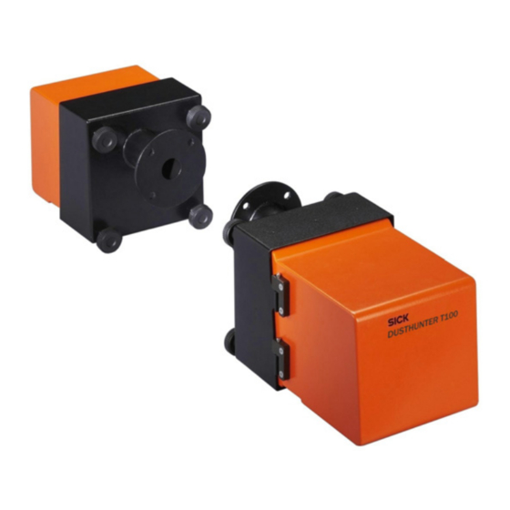
- Page 115 Dimensions, Part Nos. 7. 2 All measures are specified in mm. Sender/receiver unit 7.2.1 DHT-T00 Figure 85 Sender/receiver unit Name Part number Sender/receiver unit DHT-T00 1043902 DUSTHUNTER T · Operating Instructions · 8012428 V 2.0 · © SICK MAIHAK GmbH Germany...
- Page 116 Specifications Figure 86 Sender/receiver unit DHT-T01, DHT-T21 Name Part number Sender/receiver unit DHT-T10 1043903 Sender/receiver unit DHT-T21 1043904 DUSTHUNTER T · Operating Instructions · 8012428 V 2.0 · © SICK MAIHAK GmbH Germany...
- Page 117 Figure 88 Reflector DHT-R0x, DHT-R1x Name Part number Reflector DHT-R00 1043905 Reflector DHT-R10 1043906 Reflector DHT-R01 1043907 Reflector DHT-R11 1043908 Reflector DHT-R02 1044093 Reflector DHT-R12 1044244 DUSTHUNTER T · Operating Instructions · 8012428 V 2.0 · © SICK MAIHAK GmbH Germany...
- Page 118 Flange with tube, Di = 70.2 Length 130 mm, 1.4571 2017846 Flange with tube, Di = 70.2 Length 240 mm, 1.4571 2017848 Flange with tube, Di = 70.2 Length 500 mm, 1.4571 2017850 DUSTHUNTER T · Operating Instructions · 8012428 V 2.0 · © SICK MAIHAK GmbH Germany...
- Page 119 Control unit MCU-N2ODN01000NN in wall housing (orange), 1045003 Supply voltage 24 V DC, without purge air unit, with display Only for DUSTHUNTER T50 For DUSTHUNTER T100 and T200 DUSTHUNTER T · Operating Instructions · 8012428 V 2.0 · © SICK MAIHAK GmbH Germany...
- Page 120 Control unit MCU-P2ODN01000NN in wall housing (orange), 1045004 Supply voltage 24 V DC, with purge air unit, with display Only for DUSTHUNTER T50 For DUSTHUNTER T50, T100 and T200 DUSTHUNTER T · Operating Instructions · 8012428 V 2.0 · © SICK MAIHAK GmbH Germany...
- Page 121 Purge air unit with blower 2BH13 and purge air hose, length 5 m 1012424 Purge air unit with blower 2BH13 and purge air hose, length 10 m 1012409 DUSTHUNTER T · Operating Instructions · 8012428 V 2.0 · © SICK MAIHAK GmbH Germany...
- Page 122 Weatherproof cover for purge air unit 5306108 Weatherproof cover for sender/receiver unit and reflector Figure 94 Weatherproof cover for analyzer Name Part number Weatherproof cover for analyzer 2702407 DUSTHUNTER T · Operating Instructions · 8012428 V 2.0 · © SICK MAIHAK GmbH Germany...
- Page 123 Interface module Profibus DP V0 2040961 Interface module Ethernet 2040965 Misc. 7.3.7 Name Part number Adjusting holder 2042907 Optical adjusting device for flange assembly 1700462 DUSTHUNTER T · Operating Instructions · 8012428 V 2.0 · © SICK MAIHAK GmbH Germany...
- Page 124 7.4.2 Name Number Part number Filter element C1140 7047560 Optional external purge air unit 7.4.3 Name Number Part number Filter element Micro-Topelement C11 100 5306091 DUSTHUNTER T · Operating Instructions · 8012428 V 2.0 · © SICK MAIHAK GmbH Germany...
- Page 125 SICKOPTIC password must be entered If a wrong key is pressed when entering the password, the window must be closed and then the entering repeated. DUSTHUNTER T · Operating Instructions · 8012428 V 2.0 · © SICK MAIHAK GmbH Germany...
- Page 127 You will find our local subsidiary or agency at: www.sick.com Your local sales and service partner SICK MAIHAK GmbH | Germany Nimburger Str. 11 | 79276 Reute | www.sick.com Phone +49 7641 469-0 | Fax +49 7641 469-11 49 | info.pa@sick.de...
- Page 128 Title Page O P E R A T I N G I N S T R U C T I O N S 2.0 GMS800 GMS800 Series Extractive Gas Analyzers Basic information for all products in the series...
- Page 129 SICK MAIHAK GmbH assumes no liability for the correctness of an unauthorized translation. Please contact the manufacturer in case of doubt. Legal information Subject to change without notice © SICK MAIHAK GmbH. All rights reserved. GMS800 · Operating Instructions · 8013025 V 1.2 · © SICK MAIHAK GmbH...
- Page 130 Risk or hazardous situation which could result in severe personal injury or death. CAUTION Hazard or unsafe practice which could result in personal injury or property damage. NOTICE Hazard which could result in property damage. GMS800 · Operating Instructions · 8013025 V 1.2 · © SICK MAIHAK GmbH...
- Page 131 Measures after start-up ............31 GMS800 · Operating Instructions · 8013025 V 1.2 · © SICK MAIHAK GmbH...
- Page 132 Simple test method for gas leak tightness ........54 GMS800 · Operating Instructions · 8013025 V 1.2 · © SICK MAIHAK GmbH...
- Page 133 ........61 GMS800 · Operating Instructions · 8013025 V 1.2 · © SICK MAIHAK GmbH...
- Page 134 Important Information GMS800 Important Information Main safety information Main operating information Intended use Responsibility of user GMS800 · Operating Instructions · 8013025 V 1.2 · © SICK MAIHAK GmbH...
- Page 135 When the GMS800 is operated with enclosure purging or enclosure pressur- ization: Observe the stipulated start-up procedure. Maintain the stipulated operating conditions. ⊗ Do not open the enclosure during operation. [1] → Supplementary Operating Instructions for Enclosure GMS800 · Operating Instructions · 8013025 V 1.2 · © SICK MAIHAK GmbH...
- Page 136 If severe damage is visible on or in the device: Shut device down and secure against unauthorized start-up. If liquids or particles have penetrated the enclosure: Shut device down immediately and disconnect mains voltage at external source. GMS800 · Operating Instructions · 8013025 V 1.2 · © SICK MAIHAK GmbH...
- Page 137 If the sample gas composition has changed in such cases: Carry out an adjustment with new test gases that correspond to the changed conditions. This may not be necessary when the GMS800 automatically compensates such effects. GMS800 · Operating Instructions · 8013025 V 1.2 · © SICK MAIHAK GmbH...
- Page 138 Inform persons who can be in the area on safety-relevant aspects. Keeping documents Keep these Operating Instructions and all associated documents available for reference. Pass the documents on to a new owner. GMS800 · Operating Instructions · 8013025 V 1.2 · © SICK MAIHAK GmbH...
- Page 139 Pay primary attention to the individual information and specifications delivered with the device. If the GMS800 is delivered as part of a measuring system: Refer to the separate documents delivered for further information. GMS800 · Operating Instructions · 8013025 V 1.2 · © SICK MAIHAK GmbH...
- Page 140 Product Description GMS800 Product Description Product identification Functional principle GMS800 product family GMS800 · Operating Instructions · 8013025 V 1.2 · © SICK MAIHAK GmbH...
- Page 141 B Fitted analyzer modules XXXXXXXX 50-300 VA IP 40 C Product key Certification Certification Qa: S01 Tested: XXXXX Date: MM/YYYY Maihak AG D-22399 Hamburg Made in Germany GMS800 · Operating Instructions · 8013025 V 1.2 · © SICK MAIHAK GmbH...
- Page 142 B Extracted sample gas C Sample gas conditioning D Gas analyzer Operating conditions for sample gas feed → Supplementary Operating Instruc- tions for the Analyzer Modules fitted GMS800 · Operating Instructions · 8013025 V 1.2 · © SICK MAIHAK GmbH...
- Page 143 Product Description Fig. 3 Product components Enclosures Control unit GMS810 GMS815P Analyzer modules UNOR-MULTOR DEFOR OXOR-P GMS820P OXOR-E THERMOR Gas module GMS830 · GMS831 I/O module(s) GMS800 · Operating Instructions · 8013025 V 1.2 · © SICK MAIHAK GmbH...
- Page 144 OXOR-P Paramagnetism , high requirements THERMOR Thermal conductivity , CO , He and others UNOR-MULTOR NDIR 1 to 4 IR measuring components [1] For measuring component NO GMS800 · Operating Instructions · 8013025 V 1.2 · © SICK MAIHAK GmbH...
- Page 145 1 or 2 I/O modules (per device configuration) Monitoring and controlling with PC + PC software “SOPAS ET” The maximum configuration may be restricted for some enclosure types. GMS800 · Operating Instructions · 8013025 V 1.2 · © SICK MAIHAK GmbH...
- Page 146 Gas module Analyzer module I/O module Additional separator couplers must be fitted to the CAN bus when the modules are installed physically separated (e.g. in system cabinets). GMS800 · Operating Instructions · 8013025 V 1.2 · © SICK MAIHAK GmbH...
- Page 147 Product Description GMS800 · Operating Instructions · 8013025 V 1.2 · © SICK MAIHAK GmbH...
- Page 148 Installation GMS800 Installation Scope of delivery Project planning Connections GMS800 · Operating Instructions · 8013025 V 1.2 · © SICK MAIHAK GmbH...
- Page 149 Using signal connections Proper installation meeting application requirements is the prerequisite for correct device functions and measuring results. Recommendation: Allow qualified skilled persons to plan and carry out installation. GMS800 · Operating Instructions · 8013025 V 1.2 · © SICK MAIHAK GmbH...
- Page 150 [2] In preparation WARNING: Hazards from noxious sample gases When the sample gas contains substances dangerous to health: Check whether additional safety precautions are necessary (→ p. 11, §1.5). GMS800 · Operating Instructions · 8013025 V 1.2 · © SICK MAIHAK GmbH...
- Page 151 Providing special gas connections (only for special versions) 3.3.5 Special versions of the GMS800 may possibly be fitted with individual gas connections (e.g. for a second sample gas path). Observe the individual information provided. GMS800 · Operating Instructions · 8013025 V 1.2 · © SICK MAIHAK GmbH...
- Page 152 1 Extraction point 2 Dust filter 3 Heated sample gas line 4 Gas pump 5 Sample gas cooler 6 Fine dust filter 7 Test gases 8 Gas analyzer GMS800 · Operating Instructions · 8013025 V 1.2 · © SICK MAIHAK GmbH...
- Page 153 European standard EN 61010 specifies that any fix-mounted devices not having an own mains switch must be equipped with an external mains switch. Connect mains connection 3.4.4 → Supplementary Operating Instructions for Enclosure GMS800 · Operating Instructions · 8013025 V 1.2 · © SICK MAIHAK GmbH...
- Page 154 3.5.2 Signal connections … See for information → Supplementary Operating Instructions for “I/O On an internal I/O module Module” → Relevant separate information On other external components GMS800 · Operating Instructions · 8013025 V 1.2 · © SICK MAIHAK GmbH...
- Page 155 Setting the internal configuration CAN bus External System modules can be connected to the CANopen interfaces. One of the CANopen connections is reserved for the CAN bus terminator (terminating resistor). GMS800 · Operating Instructions · 8013025 V 1.2 · © SICK MAIHAK GmbH...
- Page 156 Start-up GMS800 Start-up Safe preparation Switch-on procedure Individual adaptations GMS800 · Operating Instructions · 8013025 V 1.2 · © SICK MAIHAK GmbH...
- Page 157 (e.g. sample gas cooler). Wait until heated system components have reached operating temper- ature (e.g. heated sample gas line). [1] If fitted GMS800 · Operating Instructions · 8013025 V 1.2 · © SICK MAIHAK GmbH...
- Page 158 Each module has a function in the Menu system which shows the module state with LED symbols. Measures after start-up 4 . 3 Carry out an adjustment (→ p. 39, §6). [1] In preparation GMS800 · Operating Instructions · 8013025 V 1.2 · © SICK MAIHAK GmbH...
- Page 159 Start-up GMS800 · Operating Instructions · 8013025 V 1.2 · © SICK MAIHAK GmbH...
- Page 160 Operation GMS800 Operation Operating elements Menu system Operating state recognition Behavior in an emergency GMS800 · Operating Instructions · 8013025 V 1.2 · © SICK MAIHAK GmbH...
- Page 161 The display lighting can possibly switch off automatically after a certain time (→ Operating Instructions “BCU”). To reactivate the display lighting: Touch the left or right function button. GMS800 · Operating Instructions · 8013025 V 1.2 · © SICK MAIHAK GmbH...
- Page 162 5.2.3 Certain menu functions are only available when user level “Authorized operator” is active. Trained and authorized skilled persons can make advanced parameter settings at “Service” level. GMS800 · Operating Instructions · 8013025 V 1.2 · © SICK MAIHAK GmbH...
- Page 163 When the GMS800 is in an unsafe state or could be: Put the GMS800 out of operation, disconnect from the mains voltage and signal voltage and secure against unallowed or accidental start-up. GMS800 · Operating Instructions · 8013025 V 1.2 · © SICK MAIHAK GmbH...
- Page 164 1 Disconnect the GMS800 from the mains voltage (mains switch or emergency switch). 2 Stop gas feed to the GMS800. 3 Prevent unauthorized or unintentional start-up. 4 Protect the measuring system against condensation and penetration by liquids. GMS800 · Operating Instructions · 8013025 V 1.2 · © SICK MAIHAK GmbH...
- Page 165 Operation GMS800 · Operating Instructions · 8013025 V 1.2 · © SICK MAIHAK GmbH...
- Page 166 Adjustment GMS800 Adjustment Introduction Guideline Preparations Adaptations Procedures GMS800 · Operating Instructions · 8013025 V 1.2 · © SICK MAIHAK GmbH...
- Page 167 To attain complete adjustment, this procedure must be performed twice for each measuring component – once for the zero point and once for the reference point. Sequence control programs control these procedures (→ Technical Information for Control Unit). GMS800 · Operating Instructions · 8013025 V 1.2 · © SICK MAIHAK GmbH...
- Page 168 Controls automatic gas Control signal Controls the adjustment feed procedure Electric control Nominal value Adjustment signal Analyzer module Adjusts based on nominal and actual values Test gases GMS800 · Operating Instructions · 8013025 V 1.2 · © SICK MAIHAK GmbH...
- Page 169 → Technical Infor- mation for Control Unit Fully automatic (cyclic) As in [C] + programmed cyclic adjustment trigger [1] → Technical Information for Control Unit GMS800 · Operating Instructions · 8013025 V 1.2 · © SICK MAIHAK GmbH...
- Page 170 These effects must be known quantitatively and considered appropriately when setting the zero gas nominal value. Pay primary attention to the individual information provided on zero gas. GMS800 · Operating Instructions · 8013025 V 1.2 · © SICK MAIHAK GmbH...
- Page 171 Pay primary attention to the span gas information in the Supplementary Operating Instructions for the Analyzer Modules fitted. Pay primary attention to the individual information provided. GMS800 · Operating Instructions · 8013025 V 1.2 · © SICK MAIHAK GmbH...
- Page 172 On devices with a sample gas pump: Make sure the feed pressure of the test gases is limited (check pressure regulator). Otherwise the fitted sample gas pump can be damaged. GMS800 · Operating Instructions · 8013025 V 1.2 · © SICK MAIHAK GmbH...
- Page 173 H O, the sample gas cooler can dry out during the course of a long adjustment procedure. This would neutralize the advantages of this method. GMS800 · Operating Instructions · 8013025 V 1.2 · © SICK MAIHAK GmbH...
- Page 174 Shutdown GMS800 Shutdown Protective measures Switch-off procedure Disposal GMS800 · Operating Instructions · 8013025 V 1.2 · © SICK MAIHAK GmbH...
- Page 175 When the enclosure is fitted with an active system for enclosure pressurization (e.g. inert gas purging): Shut the enclosure pressurization system down (→ Operating Instructions for the system involved). GMS800 · Operating Instructions · 8013025 V 1.2 · © SICK MAIHAK GmbH...
- Page 176 Make sure there is sufficient clearance from the walls of the container. Accompanying documents when shipping for repairs → §7.6 GMS800 · Operating Instructions · 8013025 V 1.2 · © SICK MAIHAK GmbH...
- Page 177 »soft« gas path material (e.g. hoses, sealing rings). Sample gas filter: Sample gas filters can be contaminated with pollutants. Electronics: Electrolyte capacitors, tantalum capacitors Display: Liquid of the Liquid Crystal Display (LCD) GMS800 · Operating Instructions · 8013025 V 1.2 · © SICK MAIHAK GmbH...
- Page 178 Maintenance GMS800 Maintenance Maintenance plan Visual inspection Cleaning Leak tightness check GMS800 · Operating Instructions · 8013025 V 1.2 · © SICK MAIHAK GmbH...
- Page 179 [8] Only for devices with DEFOR Analyzer module and measuring component NO Note Explanation Maintenance interval depends on the individual application Carry out at the manufacturer's factory or workshop with suitable equipment GMS800 · Operating Instructions · 8013025 V 1.2 · © SICK MAIHAK GmbH...
- Page 180 (e.g. pull out the mains cable at the socket or switch off the external mains fuse). Contact the manufacturer’s customer service or other trained skilled persons able to repair the device. GMS800 · Operating Instructions · 8013025 V 1.2 · © SICK MAIHAK GmbH...
- Page 181 5 mm (outlet opening diameter). – Plain water can be used as filling. Only use enough water so that no water can escape via the gas outlet of the washing bottle. GMS800 · Operating Instructions · 8013025 V 1.2 · © SICK MAIHAK GmbH...
- Page 182 – To release the gas pressure: Carefully loosen the connection hose on the washing bottle gas outlet. – Reconnect the gas connection on the gas analyzer as for operating mode - pay careful attention to gas leak tightness. GMS800 · Operating Instructions · 8013025 V 1.2 · © SICK MAIHAK GmbH...
- Page 183 Maintenance GMS800 · Operating Instructions · 8013025 V 1.2 · © SICK MAIHAK GmbH...
- Page 184 Clearing Malfunctions GMS800 Clearing Malfunctions General malfunctions Malfunction messages Display messages Measurement errors GMS800 · Operating Instructions · 8013025 V 1.2 · © SICK MAIHAK GmbH...
- Page 185 The Logbook contains the malfunctions of a module in tabular form with an error code (→ Supplementary Operating Instructions for Modules). “SOPAS ET” blends in the significance of the error code after clicking the Logbook table once. GMS800 · Operating Instructions · 8013025 V 1.2 · © SICK MAIHAK GmbH...
- Page 186 Install separate exhaust gas line for – at the sample gas outlet. the GMS800 . Strong mechanical vibrations. Check ambient conditions where the – GMS800 is installed. GMS800 · Operating Instructions · 8013025 V 1.2 · © SICK MAIHAK GmbH...
- Page 187 Clearing Malfunctions GMS800 · Operating Instructions · 8013025 V 1.2 · © SICK MAIHAK GmbH...
- Page 188 Technical Data (Information) GMS800 Technical Data (Information) GMS800 · Operating Instructions · 8013025 V 1.2 · © SICK MAIHAK GmbH...
- Page 189 Mains connection Electrical safety Technical gas requirements → Supplementary Operating Instructions for the Analyzer Modules fitted Metrological data → Supplementary Operating Instructions for Signal connections “I/O Module” GMS800 · Operating Instructions · 8013025 V 1.2 · © SICK MAIHAK GmbH...
- Page 190 Disposal ........50 GMS800 · Operating Instructions · 8013025 V 1.2 · © SICK MAIHAK GmbH...
- Page 191 Responsibility of user ......11 GMS800 · Operating Instructions · 8013025 V 1.2 · © SICK MAIHAK GmbH...
- Page 192 Type plate ....... . . 14 GMS800 · Operating Instructions · 8013025 V 1.2 · © SICK MAIHAK GmbH...
- Page 193 GMS800 SICK worldwide You will find our local subsidiary or agency at: www.sick.com Your local sales and service partner SICK MAIHAK GmbH Germany Nimburger Str. 11 79276 Reute www.sick.com Phone +49 7641 469-0 Fax +49 7641 469-11 49 info.pa@sick.de...
- Page 194 3.0 FLOWSIC100 O p e r a t i n G i n s t r u c t i O n s FLOWSIC100 Gas Velocity and Volume Flow Measuring Device Analyzers and Process Instrumentation...
- Page 195 Response Time ......................41 Check Cycle ........................42 2.5.1 Zero-point Check......................42 2.5.2 Span Test ........................43 2.5.3 Check Cycle on the Analog Output ................43 Technical Data ........................44 8012513/03-2008 © SICK MAIHAK GmbH · Germany · All rights reserved...
- Page 196 General Notes ....................... 87 4.1.2 Installing the SOPAS ET Operation and Configuration Software ....... 88 4.1.3 Connecting the Device....................90 4.1.4 Using the SOPAS ET Configuration Software .............. 92 4.1.5 Online-Help........................93 © SICK MAIHAK GmbH · Germany · All rights reserved 8012513/03-2008...
- Page 197 6 Parts Overview......................131 Standard Components....................133 6.1.1 Sender/Receiver Units ....................133 6.1.2 Flanges with Tube....................... 135 6.1.3 Connection Cable......................136 6.1.4 Control Unit MCU ......................136 6.1.5 Miscellaneous ......................136 8012513/03-2008 © SICK MAIHAK GmbH · Germany · All rights reserved...
- Page 198 Options..........................137 6.2.1 Control Units........................ 137 6.2.2 Purge-air Units......................137 6.2.3 Weatherproof Cover....................137 6.2.4 Miscellaneous ......................137 Consumable Parts for 2-Year Operation..............138 9 Appendix........................139 Password ......................... 141 © SICK MAIHAK GmbH · Germany · All rights reserved 8012513/03-2008...
- Page 199 These operating instructions only cover standard applications that match the technical data listed. Your SICK MAIHAK representative will gladly provide you with additional information and support for special applications. We strongly advise that you contact a SICK MAIHAK specialist for consultation with regard to special applications.
- Page 200 • Suitable safety equipment and personal protection measures must be available in accordance with the potential hazard and must be used by the personnel. © SICK MAIHAK GmbH · Germany · All rights reserved 8012513/03-2008...
- Page 201 • A rise in system component temperature, • Triggering of monitoring devices, • Unusually strong vibrations / unusual operating noise from a purge-air fan, • Smoke or unusual odors. © SICK MAIHAK GmbH · Germany · All rights reserved 8012513/03-2008...
- Page 202 • The maintenance personnel is sufficiently qualified to respond to malfunctions on the FLOWSIC100 and any resulting malfunctions, • The defective equipment can be switched off immediately if necessary, • Switching off equipment does not indirectly cause further malfunctions. © SICK MAIHAK GmbH · Germany · All rights reserved 8012513/03-2008...
- Page 203 FLOWSIC100 Gas Velocity Monitor Product Description Features and Applications System Overview and Operating Principle System Components Calculations Check Cycle Technical Data Dimensions...
- Page 205 – Drying and processing installations in the pharmaceutical, food, and foodstuffs industries – Heat treatment and extraction plants used in plastics processing • Flow measurements in ventilation, heating, and air-conditioning systems in both industry and agriculture 8012513/03-2008 © SICK MAIHAK GmbH · Germany · All rights reserved...
- Page 206 Operating Instructions Gas Velocity Monitor Certification The measuring system is qualified to the Federal German Pollution Control Act (13th, 17th, and 27th Implementing Ordinances) and the Clean Air Regulations (TA-Luft). © SICK MAIHAK GmbH · Germany · All rights reserved 8012513/03-2008...
- Page 207 Spool piece with flanges, preassembled for mounting in an existing pipe; with flanges with pipe for fitting the sender/receiver units FLSE100 sender/receiver unit Duct Flange with pipe control unit FLSE100 sender/receiver unit Connection cable Connection box Fig. 2.1: FLOWSIC100 system components 8012513/03-2008 © SICK MAIHAK GmbH · Germany · All rights reserved...
- Page 208 (see Service Manual Section 3.1). • Other sensor type (e.g. sensor for dust measurement) can be connected additionally to the MCU too. © SICK MAIHAK GmbH · Germany · All rights reserved 8012513/03-2008...
- Page 209 Sender/ receiver direction opposite the gas unit master flow Fig. 2.4: Operating principle of the FLOWSIC100 8012513/03-2008 © SICK MAIHAK GmbH · Germany · All rights reserved...
- Page 210 The process parameters "pressure", "temperature", and "humidity content" are required to calculate the volumetric flow under standard conditions. A more detailed description is provided in Section 2.4.. © SICK MAIHAK GmbH · Germany · All rights reserved 8012513/03-2008...
- Page 211 Pressure-resistant versions must be used with pressures greater than 100 mbar (see OI FLOWSIC100 PROCESS) • Certification requirements Qualification tests for emission measurements, explosion protection requirements, pressure stages (also see OI FLOWSIC100 PROCESS), 8012513/03-2008 © SICK MAIHAK GmbH · Germany · All rights reserved...
- Page 212 350mm duct probe material 1.4571 transducer made from titanium The possible versions, areas of application, configurations, and characteristics are listed in the following tables. © SICK MAIHAK GmbH · Germany · All rights reserved 8012513/03-2008...
- Page 213 • purged, • high power, • digital signal transfer to control unit • purged, • very high power, • digital signal transfer to control unit 8012513/03-2008 © SICK MAIHAK GmbH · Germany · All rights reserved...
- Page 214 100 g/m³ 3.1.3 for installation across secant (see Section Configuration options Type FLSE100 Duct probe Nominal length in mm Material SA/SD PRAC © SICK MAIHAK GmbH · Germany · All rights reserved 8012513/03-2008...
- Page 215 Electronics unit Connection M Duct probe Transducer available with other flanges on request (see Section 2.7.1). NL = 200 mm 350 mm Cable connection 550 mm Fig. 2.6: FLSE100-M 8012513/03-2008 © SICK MAIHAK GmbH · Germany · All rights reserved...
- Page 216 Cable connection analog 350 mm Fig. 2.9: FLSE100-SA Electronics unit Connection SD Duct probe Transducer NL = 125 mm, 200 mm, Cable connection analog 350 mm Fig. 2.10: FLSE100-SD © SICK MAIHAK GmbH · Germany · All rights reserved 8012513/03-2008...
- Page 217 Type FLSE100-MAC can be supplied with different flanges on request (see Section 2.7.1). NL =350 mm, 550 mm Cooling air outlet Shroud Purge-air connection Cable connection Fig. 2.11: FLSE100-HAC 8012513/03-2008 © SICK MAIHAK GmbH · Germany · All rights reserved...
- Page 218 Cable connection Fig. 2.12: FLSE100-MAC Electronics unit Connection PR / PRAC Duct probe Transducer Cooling air outlet NL =550 mm, 750 mm Cable connection Purge-air entry Fig. 2.13: FLSE100-PRAC © SICK MAIHAK GmbH · Germany · All rights reserved 8012513/03-2008...
- Page 219 Duct wall = Nominal length sender/receiver unit FLSE100 = Nominal length flange with pipe Fig. 2.15: Use of sender/receiver units with a nominal length greater than the flange with pipe 8012513/03-2008 © SICK MAIHAK GmbH · Germany · All rights reserved...
- Page 220 S, M, MAC, H, HAC, PR, PM, PH, PHS (others on M, MAC, H, HAC, PR, PRAC, PM, PH, PHS, request) H, PR, PRAC, PM, PH, PHS Fig. 2.16: Flange with pipe © SICK MAIHAK GmbH · Germany · All rights reserved 8012513/03-2008...
- Page 221 1 relay 2 relay 3 relay 4 relay 5 BUS - S/E unit 1 Term Fig. 2.17: Control unit MCU with options 8012513/03-2008 © SICK MAIHAK GmbH · Germany · All rights reserved...
- Page 222 • Maintenance • Temperature, separate zero point pressure, moisture), sensor • Control cycle check resolution 12 bits resolution 12 bits • • Warning separate span check • Limit value © SICK MAIHAK GmbH · Germany · All rights reserved 8012513/03-2008...
- Page 223 1 to 4 Relay 5 Relays Relay 4 1 to 5 Relay 3 RS232 Wide-range Relay 2 power pack Relay 1 90 ... 250 V Fig. 2.19: MCU block circuit diagram 8012513/03-2008 © SICK MAIHAK GmbH · Germany · All rights reserved...
- Page 224 Fig. 2.20: LCD in graphical display (left) and in text display (right) If a threshold value is exceeded, the display alternates between the measured values and an alarm message. © SICK MAIHAK GmbH · Germany · All rights reserved 8012513/03-2008...
- Page 225 Module to pass measured values, system status and service information to higher level via RS485 according to control systems, optional for Profibus and Ethernet, To insert in slots (see Fig. 2.21). DIN 19245 Part 3 as well as IEC 61158. 8012513/03-2008 © SICK MAIHAK GmbH · Germany · All rights reserved...
- Page 226 Connections supply for digital inputs 1 to 4 Connections for Connections for relays 1 to 5 sender/receiver unit master Fig. 2.21: Connections on the MCU processor board © SICK MAIHAK GmbH · Germany · All rights reserved 8012513/03-2008...
- Page 227 - E: Ethernet - P: Profibus Misc. (e.g. Ex design) - N: no special feature : Not valid for FLOWSIC100 : Up to 4 analog modules available on request 8012513/03-2008 © SICK MAIHAK GmbH · Germany · All rights reserved...
- Page 228 We recommend the cable type UNITRONIC Li2YCYv(TP) 2x2x0.5 mm with reinforced outer sheath (from Lappkabel). The total length of the cable between connection box and MCU (customer cable) can be up to 1000 m. © SICK MAIHAK GmbH · Germany · All rights reserved 8012513/03-2008...
- Page 229 (optional purge-air reducer set) or a purge-air unit with a more powerful fan. Internal duct pressure (mbar) Reducer Fan type -100 ... -20 40/7 2BH1300 -20 ... -10 40/10 -10 ... +30 +30 ... +100 2BH1400 8012513/03-2008 © SICK MAIHAK GmbH · Germany · All rights reserved...
- Page 230 L = 5 x DN for DN 150 to DN 200 L = 3 x DN Installation on for DN > 200 one side to DN 500 Fig. 2.24: Measuring pipe option © SICK MAIHAK GmbH · Germany · All rights reserved 8012513/03-2008...
- Page 231 SOPAS ET operating software (see Section 4.3.2). The default value from the factory is Cv2 = 0, Cv1 = 1, Cv0 = 0. 8012513/03-2008 © SICK MAIHAK GmbH · Germany · All rights reserved...
- Page 232 The calibration is carried out by means of a comparison measurement using a separate temperature sensor (for example, Pt100) with at least 2 different temperatures (see Section 4.3.3 for calculating and entering the coefficients). © SICK MAIHAK GmbH · Germany · All rights reserved 8012513/03-2008...
- Page 233 FLOWSIC100 requires more measured values to produce an output signal of the same accuracy. As a result, the response time is higher than the set time (within certain limits). 8012513/03-2008 © SICK MAIHAK GmbH · Germany · All rights reserved...
- Page 234 In this case, you should check the transducers and electronic components. If the signal amplitude or shape does not match the expected values, the transducers or electronic components are defective. In this case, an error message is output. © SICK MAIHAK GmbH · Germany · All rights reserved 8012513/03-2008...
- Page 235 SOPAS ET operating software (see Section 4.2.2). • This output is only expedient for measured values that depend on velocity (gas velocity, volumetric flow under actual conditions, volumetric flow under standard conditions). 8012513/03-2008 © SICK MAIHAK GmbH · Germany · All rights reserved...
- Page 236 90 ... 250 V AC; 50/60 Hz Power consumption Approx. 20 W types FLSE100-PM, PH, PHS, M, H, PR Approx. 25 W type FLSE100-PRAC Approx. 75 W types FLES100-MAC, HAC © SICK MAIHAK GmbH · Germany · All rights reserved 8012513/03-2008...
- Page 237 ): With high dust concentrations installation angle 60°. : With standard purge-air unit. ): With purge-air fan 2BH1400 at overpressure of > 0.03 bar (contact SICK MAIHAK). : The maximum possible dust concentration depends on the measuring distance and the gas temperature.
- Page 238 Ø 125 NL = 200 / 350 / 550 / 750 Fig. 2.27: FLSE100-H 270-280 Ø 100 506.5 Ø 125 NL = 350 / 550 / 750 Fig. 2.28: FLSE100-PR © SICK MAIHAK GmbH · Germany · All rights reserved 8012513/03-2008...
- Page 239 Ø 100* NL = 350 / 550 ** * On request delivered with pitch diameter 100mm and flange diameter 125mm ** Other nominal lengths on request Fig. 2.31: FLSE100-MAC 8012513/03-2008 © SICK MAIHAK GmbH · Germany · All rights reserved...
- Page 240 FLSE100-PM, FLSE100-PH 200, 350, 550, 750 60.3 FLSE100-PHS 350, 550, 750 Fig. 2.34: FLSE100-PM, FLSE100-PH, FLSE100-PHS *: On request delivered with pitch diameter 100 mm and flange diameter 125 mm © SICK MAIHAK GmbH · Germany · All rights reserved 8012513/03-2008...
- Page 241 H, PM, PH H, HAC, PR, PM, PH 76,1 H, HAC, PR, PRAC PM, PH H, PR, PRAC, PM, PH 114,3 350, 550, 750 Fig. 2.35: Flange with pipe 8012513/03-2008 © SICK MAIHAK GmbH · Germany · All rights reserved...
- Page 242 Control unit MCU-N (without integrated purge-air supply) Fig. 2.36: Control unit MCU-N (with display module option) Control unit MCU-P (with integrated purge-air supply ) Ø 8 Meas Fig. 2.37: MCU-P (with display module option) © SICK MAIHAK GmbH · Germany · All rights reserved 8012513/03-2008...
- Page 243 Operating Instructions FLOWSIC100 Gas Velocity Monitor 2.7.4 Purge-air Supply in Wall-Cabinet Ø 8 2.7.5 Connection Box for Connection Cable Mounting holes Ø 4 Fig. 2.38: Connection box for connection cable 8012513/03-2008 © SICK MAIHAK GmbH · Germany · All rights reserved...
- Page 244 Product Description FLOWSIC100 Operating Instructions Gas Velocity Monitor 2.7.6 Purge-air unit ø Fig. 2.39: Standard purge-air unit SLV1 Fig. 2.40: Weather-proof hood for purge-air unit © SICK MAIHAK GmbH · Germany · All rights reserved 8012513/03-2008...
- Page 245 FLOWSIC100 Gas Velocity Monitor Assembly and Installation Project Planning Assembly Installation...
- Page 247 (approx. 500 mm) Plan the Operating voltage, According to the technical data in Section 2.6 Ensure sufficient cable cross-sections power supply maximum demand and fuse 88012513/03-2008 © SICK MAIHAK GmbH · Germany · All rights reserved...
- Page 248 Outlet section Duct/ pipeline Flow distribution not Sender/receiver unit uniform downstream of curvature Uniform flow distribution Installation in short inlet section View A Fig. 3.1: Installing the sender/receiver units © SICK MAIHAK GmbH · Germany · All rights reserved 88012513/03-2008...
- Page 249 * Type M shown here Fig. 3.2: Installing the sender/receiver units on a vertical duct Note: With duct dimensions from approx. 4.5 m, an installation angle of 60° should be selected. 88012513/03-2008 © SICK MAIHAK GmbH · Germany · All rights reserved...
- Page 250 Representative wall distance, where the local gas velocity correspond to the mean velocity in the duct cross-section Fig. 3.4: Installing the sender/receiver unit type FLSE100-PR Sender/receiver units with special length can be delivered if the condition for x cannot be observed. © SICK MAIHAK GmbH · Germany · All rights reserved 88012513/03-2008...
- Page 251 (B in Fig. 2.4) of the types FLSE100-PH / PHS / H and HAC to prevent malfunctions of the measuring behavior by impacting of particles on the transducer surface. 88012513/03-2008 © SICK MAIHAK GmbH · Germany · All rights reserved...
- Page 252 ------------------------ - ----------- - – Fmin α ⋅ ----------- - 2 Le Ld – – α Dimensions in mm Fig. 3.6: Determining the nominal length of the flanges with pipe © SICK MAIHAK GmbH · Germany · All rights reserved 88012513/03-2008...
- Page 253 = 60° Fig. 3.5 Ld as in with a = a and circular ducts α then ( = 60°) =L +2 Le + Ld Fig. 3.7: Installation across secant 88012513/03-2008 © SICK MAIHAK GmbH · Germany · All rights reserved...
- Page 254 0.64 2.60 1.96 1.56 0.65 2.65 1.61 0.66 2.70 1.66 0.68 2.75 1.71 0.69 2.80 1.76 0.70 2.85 1.81 0.71 2.90 1.86 0.73 2.95 1.91 0.74 3.00 1.96 0.75 © SICK MAIHAK GmbH · Germany · All rights reserved 88012513/03-2008...
- Page 255 Le. Insulation (remove around flange area) Fig. 3.8: Installation options for the flanges with pipe 88012513/03-2008 © SICK MAIHAK GmbH · Germany · All rights reserved...
- Page 256 Duct with insulation Reinforcement Flange with pipe mounted on brick or concrete duct a) Duct without insulation b) Duct with insulation Fig. 3.9: Installation options for the flanges with pipe © SICK MAIHAK GmbH · Germany · All rights reserved 88012513/03-2008...
- Page 257 (for smaller ducts) or with the alignment device from SICK MAIHAK (can also be supplied on loan) (see Fig. 3.10). The alignment device is suitable for types H, H-AC, PM, PH only...
- Page 258 Installation on one side Sender / receiver unit b (=8 mm) 60° ±0.5° = L1 + L2 FF = F1 + F2 Fig. 3.11: Mounting the flanges with pipe © SICK MAIHAK GmbH · Germany · All rights reserved 88012513/03-2008...
- Page 259 NL (see Fig. 3.11 and Fig. 3.12). This correlation is expressed by the following formulas: 48.3 27.9 – – 48.3 -------------------- - ---------------------------- - – ⋅ α α α 45° 60° 88012513/03-2008 © SICK MAIHAK GmbH · Germany · All rights reserved...
- Page 260 325.4 553.3 525.4 Matching flanges with pipe can be provided by SICK MAIHAK on request (please specify with order). Alternatively, a pipe piece with premounted flanges can be ordered from SICK MAIHAK. A pipe with a suitable diameter can be used to align the flanges for face-to-face mounting.
- Page 261 Type connection unit MCU-N: Control unit without MCU-N MCU-P purge-air supply MCU-P: Control unit purge-air sup- 2.7.3 ply (see Section > 350 > 540 Fig. 3.13: Mounting dimensions of the MCU 88012513/03-2008 © SICK MAIHAK GmbH · Germany · All rights reserved...
- Page 262 This modules should be mounted on a level base plate (secure with 2 bolts M4x20). concrete ducts suitable mounting set are avail- Clearance for cables able. > 150 > 150 Fig. 3.14: Mounting dimensions for connection box © SICK MAIHAK GmbH · Germany · All rights reserved 88012513/03-2008...
- Page 263 Prepare the bracket as shown in Fig. 3.15. ‡ Secure the purge-air unit with 4 bolts (M8). ‡ Check whether the filter insert is installed in the filter housing; fit the insert if necessary. ‡ 88012513/03-2008 © SICK MAIHAK GmbH · Germany · All rights reserved...
- Page 264 Fig. 3.16: Assembly of the rebound protector for the types FLSE100-PH and PHS The rebound protector is located at the probe‘s head as shown in Fig. 3.16 and must be arranged facing the gas flow. © SICK MAIHAK GmbH · Germany · All rights reserved 88012513/03-2008...
- Page 265 They must be assembled according to the special leaflet sup- plied with the shipment. 88012513/03-2008 © SICK MAIHAK GmbH · Germany · All rights reserved...
- Page 266 Before you start the installation work, you must have carried out the steps described in Sec- tion 3.2. Unless otherwise agreed with SICK MAIHAK or an authorized representative, all of the in- stallation work must be carried out by the customer. This includes: Laying all the power supply and signal cables ‡...
- Page 267 (see Fig. 3.19) and secure it with a tightening strap. The purge-air outlet in the middle must be adjusted as displayed (correct if necessary) Purge-air outlet DN 40 Purge-air inlet Purge-air outlet Fig. 3.19: Underside of purge-air supply in connection box 88012513/03-2008 © SICK MAIHAK GmbH · Germany · All rights reserved...
- Page 268 Fan motor in delta connection star connection Motor Power supply circuit- breaker 4 x 1.5 mm Installed by 24 V customer Fig. 3.20: Electrical connections for the purge-air unit © SICK MAIHAK GmbH · Germany · All rights reserved 88012513/03-2008...
- Page 269 If necessary, connect a purge-air reducer (see Section 2.3.6) as shown in Fig. 3.21. Reducer approx. 200 mm Clamping tape Purge-air hose to sender/ Hose connection receiver unit Purge-air unit Fig. 3.21: Installing a purge-air reducer 88012513/03-2008 © SICK MAIHAK GmbH · Germany · All rights reserved...
- Page 270 The sender/receiver unit must be installed so that cable connection and air intake of the ‡ pump are oriented downwards. It has to be ensured that only contamination-free and dry air is taken in (use weather- ‡ proof covers if necessary). © SICK MAIHAK GmbH · Germany · All rights reserved 88012513/03-2008...
- Page 271 Insert the sender/receiver units in the flanges with pipe as previously described, and ‡ screw the components together. Connect the cable to the evaluation unit at the connector on the sender/receiver unit. ‡ 88012513/03-2008 © SICK MAIHAK GmbH · Germany · All rights reserved...
- Page 272 Connect the cables for status signals (operation/malfunction, warning, maintenance, ‡ check cycle; analog output, and external maintenance switch according to the require- ments. Connect the power supply cable to terminals L1, N, PE (see Fig. 3.23.) ‡ © SICK MAIHAK GmbH · Germany · All rights reserved 88012513/03-2008...
- Page 273 Connector assignment slave Connector assignment master RS485 to Master RS485 to MCU RS485 Connectors Fig. 3.24: Connecting the sender/receiver units to the MCU (except for type FLSE100-PR, PRAC, SA and SD) 88012513/03-2008 © SICK MAIHAK GmbH · Germany · All rights reserved...
- Page 274 (two-path measurement), variant B Connectors Connection cable slave Connector assignment Slave (length 5/10/50 m) RS485 to Master Fig. 3.25: Connecting the sender/receiver units FLSE100-PR and PRAC to the MCU © SICK MAIHAK GmbH · Germany · All rights reserved 88012513/03-2008...
- Page 275 B Analog connection cable Connection cable slave (length 5/10/50 m) FLSE100-SA Connector assignment Slave RS485 to Master Fig. 3.26: Connecting the sender/receiver units FLSE100-SA and SD to the MCU 88012513/03-2008 © SICK MAIHAK GmbH · Germany · All rights reserved...
- Page 276 Plug these modules onto the top hat rail in the MCU (see Fig. 3.22) and connect them with the cable with plug to the corresponding connector on the processor board (see Fig. 2.21). © SICK MAIHAK GmbH · Germany · All rights reserved 88012513/03-2008...
- Page 277 FLOWSIC100 Gas Velocity Monitor Commissioning and Configuration Basics Standard Commissioning Procedure Extended Commissioning Operation / Configuration with Option LCD Display...
- Page 279 These settings, however, must only be configured by adequately qualified personnel, since correct operation cannot be guaranteed if the settings are defined incorrectly. Changes of this kind should be carried out by SICK MAIHAK Service personnel only. The settings are listed in the Service Manual.
- Page 280 Insert the enclosed CD into the disk drive at the PC and follow the installation instructions ‡ (see Fig. 4.1). Note: To install the USB driver, you need administrator rights. © SICK MAIHAK GmbH · Germany · All rights reserved 8012513/03-2008...
- Page 281 Commissioning and Configuration Operating Instructions FLOWSIC100 Gas Velocity Monitor Fig. 4.1: Installing the USB driver 8012513/03-2008 © SICK MAIHAK GmbH · Germany · All rights reserved...
- Page 282 Fig. 4.3: Start menu Press the "Network Configuration" button, select the interface, press the "Advanced" ‡ button and configure according to Fig. 4.4 (settings only required during the first connection to FLOWSIC100). © SICK MAIHAK GmbH · Germany · All rights reserved 8012513/03-2008...
- Page 283 Press the "Network Scan" button in the "Network Scan Wizard" window, then the following ‡ menu appears. The following message appears if no device is found. Contact the SICK MAIHAK sercive. Fig. 4.5: Search for connected devices 8012513/03-2008 © SICK MAIHAK GmbH · Germany · All rights reserved...
- Page 284 Language Selection If necessary, set the required language in the "Tools / Options / Localization" menu (see Fig. 4.7. The settings take effect after the software has been restarted. © SICK MAIHAK GmbH · Germany · All rights reserved 8012513/03-2008...
- Page 285 Fig. 4.7: Password entry and language selection 4.1.5 Online-Help The individual menus and setting options are described in detail in the online help and are therefore not described further here. Fig. 4.8: Online Help 8012513/03-2008 © SICK MAIHAK GmbH · Germany · All rights reserved...
- Page 286 If the cross-sectional area changes in the vicinity of the measurement location, volumetric flow) enter the mean value of the areas between the sender/receiver units A and B. © SICK MAIHAK GmbH · Germany · All rights reserved 8012513/03-2008...
- Page 287 α Fig. 4.11: Basic parameters Note: For small duct dimensions <0.5 m (short measuring distances), take the thickness of the used gaskets into account when determining the measuring distance. 8012513/03-2008 © SICK MAIHAK GmbH · Germany · All rights reserved...
- Page 288 Active output Check cycle interval Time between two check cycles See Section 2.5 Hour Specification of a start time in hours, Function control start Minute minutes and seconds Second © SICK MAIHAK GmbH · Germany · All rights reserved 8012513/03-2008...
- Page 289 Mode Current at A value to be defined is output during Maintenance User defined value maintenance Mode Measured value The current measured value is output during output Maintenance Mode 8012513/03-2008 © SICK MAIHAK GmbH · Germany · All rights reserved...
- Page 290 Limit value configura- Molar mass tion Direction GasMassFlow If a value ≠ 0 is set, the limit value relais switches if the Limit value value for the selected measurand is exceeded © SICK MAIHAK GmbH · Germany · All rights reserved 8012513/03-2008...
- Page 291 ‘‘Pressure” field. Value in °C Constant Temperature Value in K Constant Setting of a value necessary for the standardization Value in mbar Pressure Constant Value in % Moisture 8012513/03-2008 © SICK MAIHAK GmbH · Germany · All rights reserved...
- Page 292 Damping time of the selected measurand (see Section 2.4.3) Sensor 1 Damping Time Value in s Damping time of additional sensors connected to the control unit Sensor 1 to 8 (bus wiring) © SICK MAIHAK GmbH · Germany · All rights reserved 8012513/03-2008...
- Page 293 The name of the file to be saved can be specified arbitrarily. It is useful to specify a name with a reference to the respective measuring location (name of company and facility). Fig. 4.16: "Project / Save Project" menu 8012513/03-2008 © SICK MAIHAK GmbH · Germany · All rights reserved...
- Page 294 Select a device, go to the subpage ‘‘Diagnosis / Protocols” and click the button for the ‡ desired type of protocol. Fig. 4.17: ‘‘Diagnosis / Protocols” subpage For the export to a PDF-file, file name and file location have to be specified. © SICK MAIHAK GmbH · Germany · All rights reserved 8012513/03-2008...
- Page 295 Commissioning and Configuration Operating Instructions FLOWSIC100 Gas Velocity Monitor Example of a Parameter Protocol Fig. 4.18: Parameter protocol FLOWSIC100 M (example) 8012513/03-2008 © SICK MAIHAK GmbH · Germany · All rights reserved...
- Page 296 If the option ‘‘View Envelope” is checked, the envelopes of both transducers are displayed. The signal shape should match the shapes in the Fig. 4.20 to Fig. 4.30, depending on the device type. © SICK MAIHAK GmbH · Germany · All rights reserved 8012513/03-2008...
- Page 297 Commissioning and Configuration Operating Instructions FLOWSIC100 Gas Velocity Monitor Type FLSE100-M /MAC Fig. 4.19: Burst form HF-signal (unconditioned signal) Fig. 4.20: Burst form demodulated signal (envelope) 8012513/03-2008 © SICK MAIHAK GmbH · Germany · All rights reserved...
- Page 298 Commissioning and Configuration FLOWSIC100 Operating Instructions Gas Velocity Monitor Type FLSE100-H /HAC / PHS Fig. 4.21: Burst form HF-signal (unconditioned signal) Fig. 4.22: Burst form demodulated signal (envelope) © SICK MAIHAK GmbH · Germany · All rights reserved 8012513/03-2008...
- Page 299 Commissioning and Configuration Operating Instructions FLOWSIC100 Gas Velocity Monitor Type FLSE100-PH Fig. 4.23: Burst form HF-signal (unconditioned signal) Fig. 4.24: Burst form demodulated signal (envelope) 8012513/03-2008 © SICK MAIHAK GmbH · Germany · All rights reserved...
- Page 300 Commissioning and Configuration FLOWSIC100 Operating Instructions Gas Velocity Monitor Type FLSE100-S Fig. 4.25: Burst form HF-signal (unconditioned signal) Fig. 4.26: Burst form demodulated signal (envelope) © SICK MAIHAK GmbH · Germany · All rights reserved 8012513/03-2008...
- Page 301 Commissioning and Configuration Operating Instructions FLOWSIC100 Gas Velocity Monitor Type FLSE100-PR / PRAC Fig. 4.27: Burst form HF-signal (unconditioned signal) Fig. 4.28: Burst form demodulated signal (envelope) 8012513/03-2008 © SICK MAIHAK GmbH · Germany · All rights reserved...
- Page 302 If additional configuration is necessary, reconnect the measuring system to the SOPAS ‡ ET software. Note: Per default all measuring paths have the same weighting in the calculation of the output value (for changing the weighting see Service Manual). © SICK MAIHAK GmbH · Germany · All rights reserved 8012513/03-2008...
- Page 303 ‡ analog output module”. New dialog boxes for ‘‘Analog Output 4 Parameter” and ‘‘Analog Output 5 Parameter” are opened. To configure more analog outputs, continue as described above. ‡ 8012513/03-2008 © SICK MAIHAK GmbH · Germany · All rights reserved...
- Page 304 Fig. 4.31: "Configuration / I/O Configuration / System Configuration" subpage Note Two of the eight measured values of every measuring unit can be selected for the cyclical data transfer if the Profibus DP module is installed. © SICK MAIHAK GmbH · Germany · All rights reserved 8012513/03-2008...
- Page 305 Go to the subpage ‘‘Internet Protocol / Internet Protocol (IP)”, activate the check box ‘‘En- ‡ able IP Communication” and click the ‘‘Add” button. Enter the desired IP-address and affirm with the OK button. ‡ Fig. 4.32: IP address specification (example) 8012513/03-2008 © SICK MAIHAK GmbH · Germany · All rights reserved...
- Page 306 If the right address has been entered, the components found on the network are display- ‡ ed as shown in the following figure. Fig. 4.34: Configuration of Ethernet module (example) © SICK MAIHAK GmbH · Germany · All rights reserved 8012513/03-2008...
- Page 307 – – FLOWSIC FLOWSIC ⋅ ⋅ CT 0 CT 1 -- - – – – PT100 PT100 FLOWSIC FLOWSIC CT 1 0 9483 – CT 0 7 7310 – 8012513/03-2008 © SICK MAIHAK GmbH · Germany · All rights reserved...
- Page 308 Select a measured value to be displayed • Switching between text and graphic display • Jumb back to main menu from submenus • Display of the contrast settings (after 2.5 s) © SICK MAIHAK GmbH · Germany · All rights reserved 8012513/03-2008...
- Page 309 AGC B: 10 dB Err A: Err B: /diag/sensor/1/warn/ /sensor/1/diag/ Back Back I/O Information Location: ... Serial: 0008701 Firmware: 1.3.15 /sensor/1//info/ Back Fig. 4.36: Menu structure of LCD display 8012513/03-2008 © SICK MAIHAK GmbH · Germany · All rights reserved...
- Page 310 MCU Variant AO Parameter FL100 1 path AI Parameter FL100 2 path MCU Variant Unlimited /io/para/ /io/para/var/ Back Enter Back Enter Fig. 4.38: Menu structure for selection of two-path measurement © SICK MAIHAK GmbH · Germany · All rights reserved 8012513/03-2008...
- Page 311 If the check box is not checked, the limit values must be defined separately. Limit Low Values for the separate scaling of the measured value bar, independent of the analog output Limit High 8012513/03-2008 © SICK MAIHAK GmbH · Germany · All rights reserved...
- Page 312 Commissioning and Configuration FLOWSIC100 Operating Instructions Gas Velocity Monitor © SICK MAIHAK GmbH · Germany · All rights reserved 8012513/03-2008...
- Page 313 FLOWSIC100 Gas Velocity Monitor Maintenance General Notes Maintaining the Sender/Receiver Units Maintaining the Purge-air Unit of the Internally Cooled Types M-AC and H-AC Maintaining the Cooling Air Supply for Device Type PR-AC Maintaining the Extern Purge-air Unit Option...
- Page 315 (as described in Chapter 1) only. If requested, all maintenance activities can also be performed by the SICK MAIHAK Service department, or an authorized service partner. SICK MAIHAK offers a range of economical maintenance and repair agreements.
- Page 316 Carefully remove the sender/receiver unit and place it in a safe location. ‡ If necessary (for example, if the duct is pressurized), seal the flange with pipe using a ‡ blind plug (available as an option). © SICK MAIHAK GmbH · Germany · All rights reserved 8012513/03-2008...
- Page 317 6 months. The activities required to replace the components (probe tube, transducers) are listed in the Service Manual. Once you have completed the work, reinstall the sender/receiver unit. 8012513/03-2008 © SICK MAIHAK GmbH · Germany · All rights reserved...
- Page 318 You do not have to switch off the purge-air unit to clean the filter housing or replace the filter insert. In other words, the sender/receiver units do not have to be removed from the duct. © SICK MAIHAK GmbH · Germany · All rights reserved 8012513/03-2008...
- Page 319 Install the filter housing back in the control unit. ‡ Clamping tape Filter housing Cover of filter housing Air intake hose Fig. 5.1: Changing the filter insert for the control unit with purge-air supply 8012513/03-2008 © SICK MAIHAK GmbH · Germany · All rights reserved...
- Page 320 ‡ Part No, 5314720 Dismount the pump from the carrier plate. ‡ Mount the new pump on the carrier plate. ‡ Reassemble the sender/receiver unit in reversed order. ‡ © SICK MAIHAK GmbH · Germany · All rights reserved 8012513/03-2008...
- Page 321 Check that the hoses are secure and free of damage. ‡ Check the filter insert for contamination. If the insert is excessively contaminated, ‡ remove it, clean the filter housing, and fit a new insert. 8012513/03-2008 © SICK MAIHAK GmbH · Germany · All rights reserved...
- Page 322 Connect the purge-air hose to the filter outlet again using the hose clamp. ‡ Filter housing Hose clamp Filter insert Purge-air hose Filter housing cover Hose clamp Quick-release lock Low-pressure monitor Air intake gland Fig. 5.3: Replacing the filter insert © SICK MAIHAK GmbH · Germany · All rights reserved 8012513/03-2008...
- Page 323 FLOWSIC100 Gas Velocity Monitor Parts Overview Standard Components MiscellaneousOptions Consumable Parts for 2-Year Operation...
- Page 325 FLSE100-H 20TITI sender/receiver unit 1042691 FLSE100-H 35TITI sender/receiver unit 1042692 FLSE100-H 55TITI sender/receiver unit 1042693 FLSE100-H 75TITI sender/receiver unit 1042694 FLSE100-H 35HSHS sender/receiver unit 1042695 FLSE100-H 55HSHS sender/receiver unit 1042696 8012513/03-2008 © SICK MAIHAK GmbH · Germany · All rights reserved...
- Page 326 Internally Cooled Version as Measuring Probes (gas temperature up to +350 °C) Name Part number FLSE100-PRAC 55SSTI sender/receiver unit 1042793 FLSE100-PRAC 75SSTI sender/receiver unit 1026405 FLSE100-PRAC 55TITI sender/receiver unit 1042794 FLSE100-PRAC 75TITI sender/receiver unit 1042795 © SICK MAIHAK GmbH · Germany · All rights reserved 8012513/03-2008...
- Page 327 Material St37, nominal length 350 mm Flange with tube D50ST550 7042282 Material St37, nominal length 550 mm Flange with tube D50SS125 7042284 SA, SD Material St37, nominal length 125 mm 8012513/03-2008 © SICK MAIHAK GmbH · Germany · All rights reserved...
- Page 328 Name Part number Purge-air hose DN 25, length 3 m 7047535 Purge-air hose DN 25, length 10 m 7047536 Connection box for connection cable 2046418 Damping set K100 2042503 © SICK MAIHAK GmbH · Germany · All rights reserved 8012513/03-2008...
- Page 329 Rebound protector for transducer (for FLSE100-PM, PH, H) 2035283 Rebound protector for transducer (for FLSE100-PHS) 7041980 Purge-air reducer set 7042093 Hook wrench (for FLSE100-H) 7042115 Optical alignment device 1700462 DME 2000 distance sensor 1010578 8012513/03-2008 © SICK MAIHAK GmbH · Germany · All rights reserved...
- Page 330 Control Unit MCU-P Name Number Part number Filter insert C1140 7047560 FLSE100-PRAC Name Number Part number Pump Mem 5,0 l/min, 24 DC pressure 6033117 Air filter WF3 complete 5314720 © SICK MAIHAK GmbH · Germany · All rights reserved 8012513/03-2008...
- Page 331 FLOWSIC 100 Gas Velocity Monitor Appendix Password...
- Page 333 Appendix Operating Instructions FLOWSIC 100 Gas Velocity Monitor Appendix 9.1 Password User level Password ‘‘Operator” none ‘‘Authorized Operator” ‘‘sickoptic” 8012513/03-2008 © SICK MAIHAK GmbH · Germany · All rights reserved...
- Page 334 Appendix FLOWSIC 100 Operating Instructions Gas Velocity Monitor © SICK MAIHAK GmbH · Germany · All rights reserved 8012513/03-2008...
- Page 336 .c om. Your local sales and service partner SICK MAIHAK GmbH | Analyzers and Process Instrumentation Nimburger Str. 11 | 79276 Reute | Germany | www.sick-maihak.com Phone +49 7641 469-0 | Fax 49 7641 469-1149 | info.sick-maihak@sick.de Analyzers and Process Instrumentation...
- Page 337 4.0 GM35 O P E R A T I N G I N S T R U C T I O N S GM35 In-Situ Gas Analyzer Continuous Measurement of CO, CO and H Concentrations in Gas Ducts Model with Measuring Probe Analyzers and Process Instrumentation...
- Page 338 Fax: +49 7641 469-49 E-Mail: info.sick-maihak@sick.de Note for the Warranty Indicated product features and technical data does not represent any warranty declaration. ' SICK MAIHAK GmbH. All rights reserved. © SICK MAIHAK GmbH • Germany · All rights reserved 8009339/2006-07...
- Page 339 4.3.2 Installing the evaluation unit (cast metal housing version) .............32 Electrical connections for the system components ..........33 4.4.1 Electrical connections for the purge air unit..................33 4.4.2 CAN bus wiring options .........................35 4.4.3 Electrical connections for the evaluation unit................36 8009389/07-2006 © SICK MAIHAK GmbH • Germany · All rights reserved...
- Page 340 8.2.3 Cleaning the optical boundary surfaces ..................68 Maintenance activities on the purge-air unit ...............69 8.3.1 Preparation and general inspection ....................69 8.3.2 Check and replace the purge-air filter.....................70 8.3.3 Restarting and checking the purge-air unit..................71 © SICK MAIHAK GmbH • Germany · All rights reserved 8009389/07-2006...
- Page 341 10.3.3 Spare Parts of the Measuring Probe ....................109 10.3.4 Spare Parts of the Evaluation Unit....................111 10.3.5 Spare parts for purge-air unit ......................112 10.3.6 Spare parts mMscellaneous......................112 10.3.7 Securing material ..........................112 8009389/07-2006 © SICK MAIHAK GmbH • Germany · All rights reserved...
- Page 342 GM35 Table of Contents Operating Instructions Probe Model © SICK MAIHAK GmbH • Germany · All rights reserved 8009389/07-2006...
- Page 343 The documentation supplied with the system and the relevant technical documentation is available to these persons for all work carried out, and these persons adhere to the instructions in this documentation in order to prevent danger or damage. 8009389/07-2006 © SICK MAIHAK GmbH • Germany · All rights reserved...
- Page 344 (depending on the installation conditions) to protect the measuring system. ‡ For measures to correct a purge air failure, see chapter 9.2, page 81 © SICK MAIHAK GmbH • Germany · All rights reserved 8009389/07-2006...
- Page 345 • Conformity with U.S. EPA specifications (CFR 40, Parts 60 and 29 CFR 1310 • EMC-conformity in accordance with EN 50081-1/EN 50082-2 CE-certification pursuant to the EC Directive EMV 89/336/EWG • The manufacturer SICK MAIHAK GmbH is certified to ISO 9001 8009389/07-2006 © SICK MAIHAK GmbH • Germany · All rights reserved...
- Page 346 To provide the purge air supply for the SR unit, with the measurimg probe, therefore, pro- tect the device against contamination and high gas temperatures. Depending on the ap- plication, 1 or 2 units are required. © SICK MAIHAK GmbH • Germany · All rights reserved 8009389/07-2006...
- Page 347 For a dimension drawing and the order data,page 106. An ANSI or DIN flange (provided by the customer) can be used instead of the flanges supplied. 8009389/07-2006 © SICK MAIHAK GmbH • Germany · All rights reserved...
- Page 348 GMP probes, the air is released into the duct 90° to the gas flow (directed purge air). The GMP probe contains a closing device towards the opening for measuring gas and is op- erated via a lever at the probe flange. © SICK MAIHAK GmbH • Germany · All rights reserved 8009389/07-2006...
- Page 349 EPA specifications, or in systems with low volumetric flow rates or irregular flow profiles. Temperature sensor PT 1000 Ceramic filter or teflon/ceramic filter, gas permeable Fig. 2 Fig. 4 GPP measuring probe (see also 8009389/07-2006 © SICK MAIHAK GmbH • Germany · All rights reserved...
- Page 350 O 2 measurement requires N 2 for purging ***) Probes with smaller active measuring distance are available on request (may be required for higher concen- trations or smaller duct diameters) © SICK MAIHAK GmbH • Germany · All rights reserved 8009389/07-2006...
- Page 351 Gas temperature [°C] – dew point temperature [°C] < abs. humidity [%] Only the numeric values, and not the units of measure, are relevant here. A data sheet for the fan heater is also available (order no. 8 008 330). 8009389/07-2006 © SICK MAIHAK GmbH • Germany · All rights reserved...
- Page 352 GM35 Product overview Operating Instructions Probe Model © SICK MAIHAK GmbH • Germany · All rights reserved 8009389/07-2006...
- Page 353 IR spectrum in conjunction with the evaluation algorithms used (see 2.2.2 „Sig- nal evaluation“). 8009389/07-2006 © SICK MAIHAK GmbH • Germany · All rights reserved...
- Page 354 If the check cycle reveals that the system is not functioning in accordance with the specifications, the GM35 measuring system outputs the appropriate error or warning messages. © SICK MAIHAK GmbH • Germany · All rights reserved 8009389/07-2006...
- Page 355 – Evaluation unit Commissioning The actual startup procedure is carried out by trained personnel or by the SICK MAIHAK Customer Service department. This procedure is described in chapter 6, page 45. The main activities carries out here include application-related adjustment on the GM35 sys- tem.
- Page 356 Pressure A mounting location with underpressure in the duct is ideal. at the measuring For duct pressures > 10 hPa (0.15 psi), please contact SICK point MAIHAK to select the correct purge air fan type. © SICK MAIHAK GmbH • Germany · All rights reserved...
- Page 357 SR unit (or- der no. 2 017 519), or two cables of this type if a GPP probe is being used, since GPP probes require a separate power supply. 8009389/07-2006 © SICK MAIHAK GmbH • Germany · All rights reserved...
- Page 358 This applies in particular to installing and removing the SR unit with measuring probe. The applicable (country-specific) accident prevention regulations must be observed at Accident prevention all times Please refer to Chapter 1 "Safety instructions", page 7 in particular. © SICK MAIHAK GmbH • Germany · All rights reserved 8009389/07-2006...
- Page 359 FL. 60 x 8 x 60 DIN 174 M 10 Working platform 50 mm (projection length in case of circular cross-section) Fig. 7 Installation model: mounting flange and purge-air unit (duct diameter not representative) 8009389/07-2006 © SICK MAIHAK GmbH • Germany · All rights reserved...
- Page 360 Instructions for mounting the flange • Standard flanges and special versions The standard flange with tube supplied by SICK-MAIHAK has a total length of 240 mm and an inside diameter of 125 mm. A version with a total length of 500 mm is available for mounting locations with thick insulation, or brick ducts.
- Page 361 Weld on junction plates for reinforcement, if possible; see Fig. 8 and Fig. 9page 25. ‡ ‡ Brick/concrete duct: secure the holding plate with welded flange with tube on the duct as shown in Fig. 9. 8009389/07-2006 © SICK MAIHAK GmbH • Germany · All rights reserved...
- Page 362 GM35 system. The prepared cables will be connected to the devices during device installation/startup by qualified personnel or by the SICK MAIHAK Customer Service department. Completed? If you have already completed the activities described here prior to delivery of the device using the "Product Information and Planning Guide", please check that you have done so...
- Page 363 Preassembled 3 binary outputs 6 x 0.5 mm with connector(s) 3 analog inputs 6 x 0.5 mm 3 analog outputs 6 x 0.5 mm Fig. 10 Cable routing diagram 8009389/07-2006 © SICK MAIHAK GmbH • Germany · All rights reserved...
- Page 364 The Evaluation Unit is usually installed in the vicinity of the measuring point so that it can be easily connected using the 4 m CAN bus cable supplied. An additional 15 m CAN bus extension cable, preassembled with connectors, is available from SICK MAIHAK as an accessory.
- Page 365 Unsuitable ambient conditions or the atmosphere in the measuring duct could cause damage to the measuring system, thereby preventing startup. Depending on the pressure, ATTENTION gas temperature, and composition of the measurement gas, opening the gas duct can cause injury. 8009389/07-2006 © SICK MAIHAK GmbH • Germany · All rights reserved...
- Page 366 The available cable length from the terminal box to the SR unit is 4 m (13.1 ft). The empty pipes for the preassembled cables laid as part of the on-site preparations must be taken into account. Mounting holes Fig. 12 Attaching the terminal box © SICK MAIHAK GmbH • Germany · All rights reserved 8009389/07-2006...
- Page 367 Mount the evaluation unit on the 4 fastening brackets at the mounting location using suit- able screws. 4 mounting holes ∅8 mm (∅0.31 in) Mounting surface Fastening brackets Fig. 13 Installing the evaluation unit (sheet metal housing) 8009389/07-2006 © SICK MAIHAK GmbH • Germany · All rights reserved...
- Page 368 Install the evaluation unit on the 3 mounting holes at the mounting location using suitable screws (M8 x 20). Fig. 15 Installing the evaluation unit (cast metal housing) ‡ Close and lock the cover. © SICK MAIHAK GmbH • Germany · All rights reserved 8009389/07-2006...
- Page 369 NO contact (switches with underpressure of approx. 35 hPa (0.5 psi) Delta connection Star connection Starting circuit-breaker Fig. 16 Purge air unit: electrical connections for the fan motor and lower-pressure monitor 8009389/07-2006 © SICK MAIHAK GmbH • Germany · All rights reserved...
- Page 370 ‡ Reconnect the power supply to the purge air unit until the measuring system is started. © SICK MAIHAK GmbH • Germany · All rights reserved 8009389/07-2006...
- Page 371 Connect the shield on the screwed connection to the housing of the terminal box. ‡ Connect the wires shown in Fig. 17 to the terminal strip; make sure that a twisted wire pair is used for CAN-H and CAN-L. 8009389/07-2006 © SICK MAIHAK GmbH • Germany · All rights reserved...
- Page 372 0...20 mA (6 x 0.5 (provided by analog inputs NC contact customer) NO contact PROFIBUS (optional) Fig. 18 Connections on the evaluation unit ‡ Open the housing door on the evaluation unit. © SICK MAIHAK GmbH • Germany · All rights reserved 8009389/07-2006...
- Page 373 Evaluation Unit Shield for the CAN cable CAN bus cable Conduit thread connection fitted to the Evaluation Unit Fig. 19 Attaching the CAN bus cable to the Evaluation Unit 8009389/07-2006 © SICK MAIHAK GmbH • Germany · All rights reserved...
- Page 374 GM35 Installation Operating Instructions Probe Model © SICK MAIHAK GmbH • Germany · All rights reserved 8009389/07-2006...
- Page 375 Displays all calculated values, such as CO LEDs Measuring mode • Operation Service mode • Service Warning message (see Diagnosis mode (diag)) • Warning Malfunction, error message (see Diagnosis mode (diag)) • Malfunction 8009389/07-2006 © SICK MAIHAK GmbH • Germany · All rights reserved...
- Page 376 When selecting a variable that requires you to enter a number, ↑ ↓ ) to select the value for each digit. use the arrows ↑ ↓ Password When prompted to specify the password, enter 1 2 3 4 with © SICK MAIHAK GmbH • Germany · All rights reserved 8009389/07-2006...
- Page 377 Manual Test ZERO Manual Test Zero gas 3 ppm CO, CO2 Zero gas CO2: 0.9 % Vol H2O: 0.4 % Vol Nullabgleich Fig. 21 Menu structure of the GM35/part 1 8009389/07-2006 © SICK MAIHAK GmbH • Germany · All rights reserved...
- Page 378 Regress. Funct. CO Span: 0.50…1.99, Zero: 0…±9999.9 Profibus Option Address: 126 PROFIBUS setting: enter bus address. Continued on page Seite 43 Fig. 22 Menu structure of the GM35/part 2 © SICK MAIHAK GmbH • Germany · All rights reserved 8009389/07-2006...
- Page 379 • Warm start: PROFIBUS DI 3: close module restarted. Test digital inputs ← back System restart Reset: default parameter settings active Fig. 23 Menu structure of the GM35/part 3 8009389/07-2006 © SICK MAIHAK GmbH • Germany · All rights reserved...
- Page 380 GM35 Handling the evaluation unit Operating Instructions Probe Model © SICK MAIHAK GmbH • Germany · All rights reserved 8009389/07-2006...
- Page 381 The application conditions specified with the purchase order have not changed. • A trained specialist at SICK MAIHAK GmbH or a SICK sales partner can be consulted if questions arise that extend beyond the scope of the standard procedures described here.
- Page 382 SR unit (see Page page 49) – Seal for sealing the measuring probe and SR unit connection Optics cloths without detergents, for example, SICK-MAIHAK order no. 4 003 353 If a weatherproof cover is used, an adhesive is required to attach the fixing bolts on the SR unit.
- Page 383 If necessary, the supply voltage for the GM35 SR unit and measuring probe can be changed on site by the SICK MAIHAK GmbH service personnel to between 115 V and 230 V. 6.3.2 Protective fittings for transportation ‡...
- Page 384 SR unit (see Fig. 25). ‡ Fix the device flange in this position by tightening the screws on the fixing ring again. © SICK MAIHAK GmbH • Germany · All rights reserved 8009389/07-2006...
- Page 385 ‡ Carefully mount the measuring probe with the device flange on the three threaded pins fitted with disk springs on the flange attachment without damaging the threads. 8009389/07-2006 © SICK MAIHAK GmbH • Germany · All rights reserved...
- Page 386 Note Adjustments or calibrations with test gases using a GPP-measuring probe represent a special case; see Chapter page 81. © SICK MAIHAK GmbH • Germany · All rights reserved 8009389/07-2006...
- Page 387 Page page 55) can be carried out at the measuring point during the warm-up time. Never- theless, due to the long warm-up time, it can be useful with measuring points that are not readily accessible to carry out the adjustment at a different location. 8009389/07-2006 © SICK MAIHAK GmbH • Germany · All rights reserved...
- Page 388 The position of the probe in XY direction can be checked over the following 2 possibilities: At the visor on the right side of the SR housing, see Fig. 39 © SICK MAIHAK GmbH • Germany · All rights reserved 8009389/07-2006...
- Page 389 The alignment is correct when the lit LED is located within the valid field within the crosshairs, or is completely within the internal ring marking of the crosshairs. 8009389/07-2006 © SICK MAIHAK GmbH • Germany · All rights reserved...
- Page 390 Wait approx. 2.5 hours after the SR unit has been connected to the power supply. Simi- larly, if you are using a GPP measuring probe, wait until this warm-up time has elapsed. © SICK MAIHAK GmbH • Germany · All rights reserved 8009389/07-2006...
- Page 391 This Chapter only applies to GM35 configurations with purge-air supply, that is, those using a GMP measuring probe. Otherwise, continue with Chapter 6.5.3. is used The purge-air unit has been installed with the device (see Pages page 44), and has been checked. 8009389/07-2006 © SICK MAIHAK GmbH • Germany · All rights reserved...
- Page 392 (Page page 54). © SICK MAIHAK GmbH • Germany · All rights reserved 8009389/07-2006...
- Page 393 Quck release fastener Flange with tube (duct side) Bolts M16x60 with nuts, washer and snap ring each Fig. 31 Mounting the SR unit with measuring probe on the duct flange 8009389/07-2006 © SICK MAIHAK GmbH • Germany · All rights reserved...
- Page 394 Connect the CAN bus cable between the SR unit and measuring probe to the socket pro- vided on the measuring probe. Connect the preassembled and preinstalled cables as shown in Fig. 32 to the underside ‡ of the SR unit. © SICK MAIHAK GmbH • Germany · All rights reserved 8009389/07-2006...
- Page 395 Call again the menu Adjust Probe on the EVU and check the display values, see page 52. ‡ ‡ Call again the measuring mode: – Quit the Diag menu or meas – press meas the button The system now starts regular measuring operation. 8009389/07-2006 © SICK MAIHAK GmbH • Germany · All rights reserved...
- Page 396 ‡ Fix the weatherproof cover in position using the two knurled nuts. A dimensioned drawing of the weatherproof cover is provided on Page page 137. © SICK MAIHAK GmbH • Germany · All rights reserved 8009389/07-2006...
- Page 397 Chapter 9.1, page 81. If the cause of the fault cannot be rectified with this information, contact the Service department at SICK MAIHAK GmbH or your local sales partner. ‡ If necessary, configure the parameters for the Evaluation Unit in accordance with your in- stallation environment.
- Page 398 GM35 Commissioning Operating Instructions Probe Model © SICK MAIHAK GmbH • Germany · All rights reserved 8009389/07-2006...
- Page 399 This method can be used to measure the zero point with nitrogen or air, as well as test points with the relevant gases and concentrations. 2nd connection: 8009389/07-2006 © SICK MAIHAK GmbH • Germany · All rights reserved...
- Page 400 Close the valve on the pressure reducer; close the gas bottle. ‡ Repeat the procedure (preparation and measurement) with the other required test gases meas ‡ Switch to Measuring mode © SICK MAIHAK GmbH • Germany · All rights reserved 8009389/07-2006...
- Page 401 Maintenance intervals The maintenance intervals depend on the specific application conditions and therefore should be clarified with the SICK-MAIHAK Service department or with a qualified engineer or technician at your local sales partner. Unless other arrangements have been made, take note of the following recommendations: •...
- Page 402 Clean cloths and brush for cleaning the inside and outside of the purge-air filter hous- Replacement parts and consumables (see Section 13.3 on page 117): – Replacement filter, SICK-MAIHAK order no. 5 306 091, if you are using a purge-air unit –...
- Page 403 Insert the measuring probe with SR unit in the angle flange from the right as shown, and secure it with at least two screws. The arrangement is important to allow the SR unit to be lifted forwards. 8009389/07-2006 © SICK MAIHAK GmbH • Germany · All rights reserved...
- Page 404 Check the cables for damage. Check for any signs of abrasion or bending at cable entries and provide protective measures if necessary. The preassembled cables are available as spare parts; if necessary contact the Service department at SICK MAIHAK GmbH. 8.2.3 Cleaning the optical boundary surfaces ‡...
- Page 405 Switch off the power supply (three phase) to the purge-air unit and, if necessary, attach a visible warning to prevent it from being reconnected inadvertently while maintenance is being carried out. 8009389/07-2006 © SICK MAIHAK GmbH • Germany · All rights reserved...
- Page 406 You can then base subsequent filter change intervals on this result. Filter housing cover Filter insert Filter housing Low-pressure monitor Fig. 38 Replacing the purge-air filter insert © SICK MAIHAK GmbH • Germany · All rights reserved 8009389/07-2006...
- Page 407 Partly cover the extraction aperture of the air filter briefly using a piece of cardboard or similar object that cannot enter the filter or cause it to be contaminated. ‡ Check whether the low-pressure monitor responds by signaling that a filter change is necessary. 8009389/07-2006 © SICK MAIHAK GmbH • Germany · All rights reserved...
-
Page 408: Resuming Measuring Mode
The function “ADJ.OPT.ALIGN” needs to be activated for systems that operate with automatic alignment, see chapter 6.4.3, page 52. © SICK MAIHAK GmbH • Germany · All rights reserved 8009389/07-2006... -
Page 409: Completing Maintenance Work At The Measuring Point
If the SR unit was equipped with a weatherproof cover, remount it. ‡ In the maintenance log, record the work carried out, as well as any special observations, and notes for future maintenance. 8009389/07-2006 © SICK MAIHAK GmbH • Germany · All rights reserved... -
Page 410: Evaluation Unit
Carry out the necessary repairs. If the Evaluation Unit is damaged (for example, LCD failure): ‡ Contact the Service department at SICK MAIHAK GmbH or your local sales representa- tive. © SICK MAIHAK GmbH • Germany · All rights reserved... -
Page 411: Filter Box Measurement For Checking The Gas Ducts Of Co And Co (Up To 15 Vol.% X M)
Attach the filter box with the adapter plate to the SR unit and secure using quick-release locks. Take care not to damage the humidity sensor of the SR unit. ‡ Install the reflector for the GM35. 8009389/07-2006 © SICK MAIHAK GmbH • Germany · All rights reserved... - Page 412 GM35 Maintenance Operating Instructions Probe Model Filter box plate Recess for humidity sensor Filter box GM35 SR unit Test gas bottle Fig. 40 Installing the filter box © SICK MAIHAK GmbH • Germany · All rights reserved 8009389/07-2006...
- Page 413 "Measuring". The overpressure generated during the purge phase decreases. ‡ Once the measured value is stable again, read the value and note it down. 8009389/07-2006 © SICK MAIHAK GmbH • Germany · All rights reserved...
-
Page 414: Resuming Measuring Mode
Attach the filter box with the adapter plate to the SR unit and secure using quick-release locks. Take care not to damage the humidity sensor of the SR unit. ‡ Install the reflector and set up the position “GM35“on the lever. © SICK MAIHAK GmbH • Germany · All rights reserved 8009389/07-2006... - Page 415 Filter box GM35 SR unit Fig. 42 Installing the filter box ‡ Insert the driving rod for filter selection completely; thereby secure that the filter is swung out. 8009389/07-2006 © SICK MAIHAK GmbH • Germany · All rights reserved...
-
Page 416: Resuming Measuring Mode
Remove the filter box along with the plate and reflector from the SR unit and store it in a safe place. ‡ Reinstall the SR unit correctly at the measuring point. © SICK MAIHAK GmbH • Germany · All rights reserved 8009389/07-2006... -
Page 417: Troubleshooting
The GM35 is equipped with an integrated system that constantly monitors the operating condition of the SR unit and evaluation unit. If deviations from normal operating conditions occur, appropriate messages are generated and logged in the devices for subsequent eval- uation. 8009389/07-2006 © SICK MAIHAK GmbH • Germany · All rights reserved... - Page 418 Start Diagnosis (diag) mode: (Warning LED possibly by the plain-text error messages – Choose Error (or Warning) menu lights up) – Check and correct the specified malfunction. • Relay 1: Group malfunction © SICK MAIHAK GmbH • Germany · All rights reserved 8009389/07-2006...
-
Page 419: Troubleshooting The Evaluation Unit
O module not connected to ‡ Check whether the cable connection is secure. Secure/repair it inside the GM35 if necessary. CO module ‡ If fault cannot be corrected: contact Service department. 8009389/07-2006 © SICK MAIHAK GmbH • Germany · All rights reserved... - Page 420 O module not connected to ‡ Contact the Service department. cell motor H2O div. zero Adjustment data of the CO O mod- ‡ Contact the Service department. ule is invalid © SICK MAIHAK GmbH • Germany · All rights reserved 8009389/07-2006...
- Page 421 Dust content too high Check the optical alignment, page 72 ‡ • IR source defective Measurement continues ‡ Replace IR source or measurement module; if necessary contact service department 8009389/07-2006 © SICK MAIHAK GmbH • Germany · All rights reserved...
- Page 422 O module not connected to ‡ Contact the Service department. cell motor H2O div. zero Adjustment data of the CO O mod- ‡ Contact the Service department. ule is invalid © SICK MAIHAK GmbH • Germany · All rights reserved 8009389/07-2006...
- Page 423 Dust content too high Check the optical alignment, page 72 ‡ • IR source defective Measurement continues ‡ Replace IR source or measurement module; if necessary contact service department 8009389/07-2006 © SICK MAIHAK GmbH • Germany · All rights reserved...
- Page 424 O module not connected to ‡ Contact the Service department. cell motor H2O div. zero Adjustment data of the CO O mod- ‡ Contact the Service department. ule is invalid © SICK MAIHAK GmbH • Germany · All rights reserved 8009389/07-2006...
- Page 425 Dust content too high Check the optical alignment, page 72 ‡ • IR source defective Measurement continues ‡ Replace IR source or measurement module; if necessary contact service department 8009389/07-2006 © SICK MAIHAK GmbH • Germany · All rights reserved...
- Page 426 O module not connected to ‡ Contact the Service department. cell motor H2O div. zero Adjustment data of the CO O mod- ‡ Contact the Service department. ule is invalid © SICK MAIHAK GmbH • Germany · All rights reserved 8009389/07-2006...
- Page 427 Dust content too high Check the optical alignment, page 72 ‡ • IR source defective Measurement continues ‡ Replace IR source or measurement module; if necessary contact service department 8009389/07-2006 © SICK MAIHAK GmbH • Germany · All rights reserved...
-
Page 428: Warning Messages For The Gm35 Sr Unit
Switch to substitute value ‡ Contact Service department if necessary HYGRO internal No communication to the onboard hu- ‡ Check cable connection midity sensor ‡ Remove sensor • Sensor defective/broken cable © SICK MAIHAK GmbH • Germany · All rights reserved 8009389/07-2006... -
Page 429: Further Tips On Troubleshooting
Relay outputs 1...4 Operating voltage: 230 V AC – no jumper 115 V AC – jumper Fuses 2.5 AT, 250 V Fig. 44 LEDs, signals, and fuses in the evaluation unit 8009389/07-2006 © SICK MAIHAK GmbH • Germany · All rights reserved... - Page 430 Connection between the evaluation unit and SR unit. ‡ Cable connection at the plug-in terminal in the evaluation unit. ‡ Cable to SR unit. ‡ Outer connectors on SR unit ‡ Inner connectors in SR unit. © SICK MAIHAK GmbH • Germany · All rights reserved 8009389/07-2006...
-
Page 431: Technical Specifications, Consumables And Spare Parts
Factor for measuring range end value (MRE) 1250 MRE * 1 1000 MRE * 1 MRE * 1.33 MRE * 2 MRE * 4 Factors for measuring range end values for standard probe lengths 8009389/07-2006 © SICK MAIHAK GmbH • Germany · All rights reserved... -
Page 432: Stability
115/230 V AC +10/–15%, 48 to 62 Hz Power consumption max. 350 W Dimensions (W x H x D) 291 x 530 x 570 mm Weight 29 kg Data og GM35 sender/receiver unit © SICK MAIHAK GmbH • Germany · All rights reserved 8009389/07-2006... - Page 433 Functional check Status inputs Inputs for external relay contacts (contact load 24 V, voltage supplied by GM35 Evaluation unit) Check cycle Autocal GM35 GM35 Evaluation Unit (Section 1 of 2) 8009389/07-2006 © SICK MAIHAK GmbH • Germany · All rights reserved...
- Page 434 50 W Dimensions, weight, class of protection Class of protection IP 65 / NEMA 4x page 106 Dimensions See dimensioned drawing on GM35 Evaluation Unit (Section 2 of 2) © SICK MAIHAK GmbH • Germany · All rights reserved 8009389/07-2006...
-
Page 435: Dimensioned Drawings
Technical specifications, consumables and spare parts Operating Instructions GM35 Probe Model 10.2 Dimensioned drawings 10.2.1 GM35 SR unit Fig. 45 Dimensions GM35 SR unit 8009389/07-2006 © SICK MAIHAK GmbH • Germany · All rights reserved... -
Page 436: With Gmp Measuring Probe
1599 1004.5 754.5 504.5 254.5 – – 2083 1489 1239 – 2.5 m 2583 1988 1738 1488 1238 application-specific lengths available on request Dimensions of the GMP measuring probes © SICK MAIHAK GmbH • Germany · All rights reserved 8009389/07-2006... -
Page 437: Gpp Measuring Probes
L3 is the length of the recess for the filter element insert, as shown in the dimensioned drawing. The active measuring path is 23 mm longer in each case, since it is formed between the optical boundary surfaces of the measuring probe. 8009389/07-2006 © SICK MAIHAK GmbH • Germany · All rights reserved... -
Page 438: Dimensions Gm35 Evaluation Unit, Steelplate Housing
Technical specifications, consumables and spare parts Operating Instructions Probe Model 10.2.4 Dimensions GM35 Evaluation Unit, steelplate housing Fig. 48 Dimensional drawing of the GM35 evaluation unit, steelplate housing model © SICK MAIHAK GmbH • Germany · All rights reserved 8009389/07-2006... -
Page 439: Dimensions Gm35 Evaluation Unit, Casting Housing
Technical specifications, consumables and spare parts Operating Instructions GM35 Probe Model 10.2.5 Dimensions GM35 Evaluation Unit, casting housing Fig. 49 Dimensional drawing of the GM35 evaluation unit, casting housing model 8009389/07-2006 © SICK MAIHAK GmbH • Germany · All rights reserved... -
Page 440: Purge-Air Unit Slv 4
Technical specifications, consumables and spare parts Operating Instructions Probe Model 10.2.6 Purge-air unit SLV 4 Fig. 50 Dimensions of the SLV 4 10.2.7 Weatherproof covers Fig. 51 Weatherproof cover for the purge-air unit © SICK MAIHAK GmbH • Germany · All rights reserved 8009389/07-2006... - Page 441 Technical specifications, consumables and spare parts Operating Instructions GM35 Probe Model 282.5 12.5 Fig. 52 Weatherproof cover for the GM35 SR unit 8009389/07-2006 © SICK MAIHAK GmbH • Germany · All rights reserved...
-
Page 442: Terminal Box For Can Bus Connection
An ANSI flange provided by the customer can 240/500 be used as an alternative. Fig. 54 Flange with tube for mounting the GM35 SR unit on the duct © SICK MAIHAK GmbH • Germany · All rights reserved 8009389/07-2006... -
Page 443: Consumables And Spare Parts
2 023 704 CAN bus cable probe – SR unit 3 x 2 x 0.74, 0.6 m long 5 700 484 Cup spring 5 700 494 Washer 5 700 472 Nut self-locking M12 Spare parts SR unit 8009389/07-2006 © SICK MAIHAK GmbH • Germany · All rights reserved... - Page 444 2 031 572 PCB set automatic alignment control R878 PL1M5–2M, probe 1.5…2 m 2 031 582 PCB set automatic alignment control R788 PL1M0, probe 1.0 m Spare parts SR unit © SICK MAIHAK GmbH • Germany · All rights reserved 8009389/07-2006...
-
Page 445: Spare Parts Of The Measuring Probe
10.3.3 Spare Parts of the Measuring Probe Order No. Description 2 023 596 Electronics board IO GPP 2 032 767 Electronics board IO GMP Spare parts of measuring probes 8009389/07-2006 © SICK MAIHAK GmbH • Germany · All rights reserved... - Page 446 2 022 515 Seal for flange 235 x 35 x 2, Neopren for GMP 4 039 022 Gasket G x P 35 126/116 x x7, graphite 5 312 881 Diffusion element Spare parts of measuring probes © SICK MAIHAK GmbH • Germany · All rights reserved 8009389/07-2006...
-
Page 447: Spare Parts Of The Evaluation Unit
2 021 795 PCB System control 6 021 782 Fuse 250 V, D8.5 x 8 6 020 125 Cap for fuse D5 x 20 6 007 328 Jumper Ersatzteile Auswerteeinheit 8009389/07-2006 © SICK MAIHAK GmbH • Germany · All rights reserved... -
Page 448: Spare Parts For Purge-Air Unit
5 700 472 Nut SSI M12 5 700 494 Spherical washer 2 017 329 Hinge bolt for GM35 flange attachment 4 023 743 Sealing tape Securing material: SR unit-measuring probe © SICK MAIHAK GmbH • Germany · All rights reserved 8009389/07-2006... - Page 449 Technical specifications, consumables and spare parts Operating Instructions GM35 Probe Model 8009389/07-2006 © SICK MAIHAK GmbH • Germany · All rights reserved...
- Page 450 GM35 Probe Model SICK MAIHAK worldwide You will find our local subsidiary or agency at: www.sick-maihak.com Your local sales and service partner SICK MAIHAK GmbH Analyzers and Process Instrumentation Nimburger Str. 11 79276 Reute Germany www.sick-maihak.com Analyzers and Process Instrumentation...
- Page 451 © Siemens AG 2011 Temperature Measurement Transmitters for rail mounting 5.0 TEMP. TRANSMITTER SITRANS TR300 two-wire system, universal, HART Overview Application SITRANS TR300 transmitters can be used in all industrial sec- tors. Their compact design enables simple mounting on stan- dard DIN rails on-site in protective boxes or in control cabinets.
- Page 452 © Siemens AG 2011 Temperature Measurement Transmitters for rail mounting SITRANS TR300 two-wire system, universal, HART Technical specifications ≤ 250 ms for 1 sensor with open- Input Response time T circuit monitoring Resistance thermometer Open-circuit monitoring Always active (cannot be dis- Measured variable Temperature abled)
- Page 453 © Siemens AG 2011 Temperature Measurement Transmitters for rail mounting SITRANS TR300 two-wire system, universal, HART Measuring range parameterizable Certificates and approvals max. -100 … 1100 mV Explosion protection ATEX Min. measured span 2 mV or 20 mV EC type test certificate PTB 07 ATEX 2032X Overload capability of the input -1.5 ...
- Page 454 © Siemens AG 2011 Temperature Measurement Transmitters for rail mounting SITRANS TR300 two-wire system, universal, HART Digital measuring errors Thermocouples Resistance thermometer Input Measuring range Min. mea- Digital sured span accuracy Input Measuring range Min. mea- Digital °C / (°F) °C (°F) °C...
- Page 455 © Siemens AG 2011 Temperature Measurement Transmitters for rail mounting SITRANS TR300 two-wire system, universal, HART Accessories Order No. Selection and Ordering data Order No. CD for measuring instruments for A5E00364512 Temperature transmitter SITRANS TR300 temperature For mounting on a standard DIN rail, two-wire With documentation in German, English, system, 4 …...
- Page 456 © Siemens AG 2011 Temperature Measurement Transmitters for rail mounting SITRANS TR300 two-wire system, universal, HART Dimensional drawings (3.9) SITRANS TR300, dimensions in mm (inch) Schematics TEST 4..20mA SIEMENS SITRANS TR300 Assignments 1 (+) and 2 (-) Test terminals (Test) for measurement of the output current with a multimeter 3 (+) and 4 (-) Power supply U...
- Page 457 © Siemens AG 2011 Temperature Measurement Transmitters for rail mounting SITRANS TR300 two-wire system, universal, HART Thermocouple Resistance thermometer Resistance Cold junction compensation Two-wire system Two-wire system internal/fixed value Cold junction compensation with Three-wire system Three-wire system external Pt100 in two-wire system Cold junction compensation with Four-wire system Four-wire system...
- Page 458 6.0 DATA LOGGER...
- Page 459 Contents Introduction System Description System Operation Function Configuration Equipment Standard Display III. Appendix D/L Installation Guide Communication Cable Connection Replace ROM of D/L MULTI-PORT D/L Expediency Table of D/L Check Up Measuring Item and Unit Change Digital I/O Connection Method Probe Purge Timing Diagram...
-
Page 460: System Description
Ⅰ. Introduction 1. System Description System Name System Application Definition of Data Logger Data Logger Configuration Map Total System Configuration... - Page 461 Ⅰ. Introduction 1. System Description (1) System Name The name of this system is Data Logger. (2) System Application Data Logger is a componential instrument of ‘ Stack TMS (Tele-Metering System)’ that is used for data collection. Other components are Analyzer, Data Logger and FEP that are used in business places.
- Page 462 (4) Data Logger Configuration Map Data Logger is a data-collecting device that is used to collect and store data from measuring instruments. The main purpose of this device is to enable collected data to be transmitted safely as arranged method. To accomplish this function, Data Logger has a configuration as follow.
- Page 463 (5) Total System Configuration Configuration of Environmental Monitoring Management Systems...
-
Page 464: System Operation
II. System Operation Function (1) Input / Output (2) Data Process Configuration Standard Display (1) Initial Screen (2) Over View Screen (3) Graph View Screen (4) Particulars Inquiry (5) Communication Monitoring (6) System Configuration (7) Communication Port Setup (8) Date/Time Setup (9) Item Setup (10) Change Password... - Page 465 1. Function The Data Logger is a data collector for Stack TMS (Tele-Metering System). It is important device as it is used for collecting data, and analyzing, storing them for transmission to the connected server. The Data Logger is able to execute the designated performance such as correction of various measuring instruments from a host computer (Ministry of Environment’...
- Page 466 2. Configuration Configuration of Data Logger is as follow. UNIT name Quantity Remark CPU Part CPU BOARD (Including CPU & MAIN MEMORY) 1 EA Refer to picture SSD BOARD (Including ROM & FLASH MEMORY) 1 EA Refer to picture SERIAL / PARALLEL PORT 1 EA P-COM BOARD 1 EA...
-
Page 467: Equipment Standard
3. Equipment Standard Data logger is divided into 'Main CPU part' and 'I/O part' as follows. MAIN CPU PART I/O PART (1) MAIN CPU PART Item Description Over Pentium (800 MHz) MAIN MEMORY Over 512 Mbytes CACHE MEMORY Over 256 KB On Board BIOS Award Flash Bios DOM (Solid State Disk) - Page 468 (2) I/O PART DIGITAL INPUT UNIT Item Description FEATURE 16 Bits MPU Intelligent, Use EPLD CHANNEL 16 or 32 Photo-Isolated Input INTERFACE Dual-port RAM Data Exchange I/O RANGE Dry-Contact (Source Input Option) Hot-Swap Function/Function Button/ Self-Diagnostic (Option) FUNCTION /Matrix-LED Function Display (RUN, ERROR, SELF TEST) DIGITAL OUTPUT UNIT Item Description...
-
Page 469: Display
4. Display (1) Initial Screen 1) Outline -. Logo -. Main menu -. Software version 2) Screen Features ① System name: "Data Logger" is the name of the system that is on the top- center of the screen. ② Date and time: Current date and time is shown on the top-right as "2002-11- 09 12:42:34". - Page 470 3) Description ① How to use Key There are two ways. One is to use ‘ Keypad’ provided on the front-right side of the ‘ Data Logger’ , and the other is to use Keyboard (PS2 type) provided as an option. To use ‘...
- Page 471 ③ Press ALT+F2, ALT+F5 for item setup and edit, then it asks ‘ password’ . Input password and press Enter to move on to the screen for setup functions. [Picture 2]...
- Page 472 2) Over View: F1 Screen 1) Outline -. Measuring data of all items in a STACK is figured with ‘ mA’ . -. AI, AO, DI, DO of each item are shown as alphabet with lamps 2) Screen Features ① Screen Name: "[OVERVIEW]" is the name at the second raw from the top. ②...
- Page 473 1 Item sequence and name: “ ITEM 00 SO2” designates sequence and name of the ITEM. “ ITEM 00” is a sequence of measuring item, and it starts with number of ‘ 00’ . The full number to set for one Stack is 10. “ SO2” is the name of measuring Item.
- Page 474 5. DI and other status lamps: DI of all items and other statuses are designated as visual signs. Full names of abbreviations are referred to the table below. < Name > Abbr Full Name ‘ CAL’ Calibration ‘ OPE’ Operation Failure ‘...
- Page 475 3) Description ① Operating KEY (Menu selection) A. Esc: Main -. Go to MAIN MENU B. F1: Graph -. Go to screen that displays graphs of each item’ s status and measuring data has been stored. C. F2: PORT - View -.
- Page 476 (3) Graph (TREND & HISTORY: F1 à F1 screen) 1) Introduction -. Provide information of a selected item in a STACK -. Display graphs of current status of an item and measuring data have been stored in a STACK. 2) Screen ①...
- Page 477 3) Description ① KEY operation (selecting menu) A. Esc: Overview -. Return to OVERVEW screen B. F1: History Dump -. Go to screen that displays stored data on STRING GRID. C. F2: PURGE -. Send PURGE signal to measuring instrument. To get the signal, setup data must be made in advance D.
- Page 478 (4) Particulars Inquiry (HISTORY DUMP: F1 à F1 à F1 screen) 1) Instruction -. Measuring data of one item in a STACK are displayed on STRING GRID numerically. -. Average values are selected by KEY with options of 5 min data and 30 min data. 2) Screen Feature ①...
- Page 479 3) Description ① KEY operation (selecting menu) A. Esc: Trend & History Graph -. Return to Trend GRAPH screen B. Up/Down: Channel -. Use to change item to monitor C. Home [7]/End [1]: Disp-Mode -. To change time zone of current data -.
- Page 480 (5) Communication Monitoring (F1 à F2 screen) 1) Outline -. Bi-directional monitor of standard transmission port and extended multi port -. Display protocol setups and transmission rates of each port 2) Screen Features ① Communication port tap: classified ports, “ COM01” means standard communication port-1.
- Page 481 [Picture 8] 3) Description ① KEY operation (selecting menu) A. Esc: Overview -. Return to OVERVIEW screen. B. PgUp/PgDn: Port modification -. Use for modify of communication port to monitor. C. F1: ENQ transmission -. It needs when communication is being tested. ENQ (05) is transmitted when press F1.
- Page 482 (6) System Configuration (F2, ALT+ F2 screen) (► setting-up and edit of items are possible by pressing ALT+F2 and entering password. F2 is for checking up.) 1) Outline -. Information of whole system and addition of communication port -. Setup each Stack’ s own environment 2) Screen structure ①...
- Page 483 A. Add-COM PORTs [0-16]: The number of communication ports added at D/L ! Caution: If added multi communication port has 2 ports, select 4PORTs. B. AREA CODE [1-99]: Area Code Yeosu area: 11 Ulsan area: 13 The Metropolitan area: 15 The central districts: 17 C.
- Page 484 ④ 1st STACK FACTOR PRESET’ s detail view A. 1st STACK NUMB [1-99]: Stack number is to being transmitted. B. ST HOST TRANS ENABLE: Yes/No for communication set-up of Stack to arranged transmission target as host port. C. STAND O2 DENSITY: Standard oxygen density of relevant Stack. D.
- Page 485 3) Description ① Key operation (menu selection) A. Esc -. Return to MAIN MENU screen. -. Before return to main menu, ask to save all changes. Press ‘ Enter’ saving. B. Up/Dn (, ¯): Item -. Go to item to modify. C.
- Page 486 (7) Communication port setup (F3 screen) 1) Outline -. Communication port set-up -. Communication protocol set-up 2) Screen Feature ① Target: set a target to be connected into the selected communication port. A. DL, HOST: Data transmission by exchanging bi-directional controlling signal. (Protocol that is defined by ‘...
- Page 487 Description ① KEY operation (menu selection) A. Esc -. Return to MAIN MENU screen -. Before return to main menu, ask to save all changes. Press Enter for saving. B. Up/Dn (, ¯): Item -. Move to item to change. C.
- Page 488 ③ Caution/Note In case data transmission (multi-transmission) by using COM1, COM2, do not set the target to be transmitted equally. For example, if this is transmitted to FEP or to HOST by both COM1 and COM2, collision may occurs during data process in internal S/W.
- Page 489 (8) Date/Time Setup (F4 screen) 1) Outline -. To modify date and time 2) Description ① Date : Year/Month/Date set-up ② Time : Time/Minute/Second set-up [Picture 15] ③ KEY operation (menu selection) A. Esc: Exit -. Return to MAIN MENU screen. -.
- Page 490 ④ How change set-up A. Move to item to change, then input Enter to go to modification mode. B. CURSOR (Up/Dn/Left/Right) KEY to modify set point. C. Input Enter after set changes. D. Input Esc to return to Main Menu. E.
- Page 491 (9) Item Setup (F5, ALT + F5 screen) (► Item set-up and correction is possible by pressing ALT+F5 and input password. To search, press F5.) 1) Outline -. Set-up item to measure and input necessary variables as each item requires. 2) Screen Features ①...
- Page 492 ② Selecting Point View screen: move bar cursor by using arrow key, then press enter. ③ ANALOG INPUT‘ s point view A. ANA-IN CHANNEL NO.: AI POINT number connected relevant item. ! Caution: if the number is 255, it is considered as disable. So, it is not connected to measuring instrument.
- Page 493 ④ ANALOG OUTPUT’ s Point View A. ANA-OUT 1st CH NO.: AO POINT number of relevant item B. ANA-OUT 2nd CH NO.: AO POINT number of relevant item C. ANA-OUT 3rd CH NO.: AO POINT number of relevant item D. ANALOG OUTPUT TYPE: Select one of output AO values, which are of calibration applied to and not applied to the AI value Data Logger.
- Page 494 ⑤ STATUS INPUT’ s Point View A. CALIBRTING: CALIBRATION signal input point number B. OPERATING FAILURE: Operating failure signal input point number C. POWER-FAILURE: Power failure signal input point number Caution: If input point number is 255, it is Disabling D.
- Page 495 ⑥ DIGITAL OUTPUT’ s Point View A. ZERO CALIBRATION: ZERO CALIBRATION signal output point number B. SPAN CALIBRATION: SPAN CALIBRATION signal output point number C. PURGE 1(SV1-SV2): PROBE PURGE1 signal output number D. PURGE 2(SV3): PROBE PURGE2 signal output number E.
- Page 496 F. PURGE HOLDING [s]: Holding the value just before Purge has done by set time. G. HOST TRANS. ENABLED: To transmit relevant measuring item to HOST or FEP port H. ZERO GAS SD-DENSITY: ZERO Standard gas density [%] I. SPAN GAS SD-DENSITY: SPAN Standard gas density [%] [Picture 22]...
- Page 497 ⑧ COMPEN. PRESET’ s Point View A. O2 COMPEN. ENABLE: Select Oxygen calibration status of relevant item. B. TEMP COMPEN. ENABLE: Select Temperature calibration status of relevant item. C. HUMI COMPEN. ENABLE: Select Humidity calibration status of relevant item. D. TEMP COMPEN. MODE: Set temperature type for temperature calibration. Select one of actual measuring temperature and Manual set temperature PARAMETER RANGE: MEASURING -- MANUAL...
- Page 498 ⑨ FLOW PRESET ‘ s Point View A. FLOW ITEM ENABLED: Setup the relevant item as flow item enabled or not. B. A/I FLOWRATE-KINDS: Setup SOURCE Type. Select one among DP, Velocity and Flow rate Parameter: Delta P -- VELOCITY -- FLOWRATE [Picture 24] 3) Description 1) KEY Operation (selecting menu)
- Page 499 How to apply range of Flow rate [Picture 25] 1) Reference dp: Maximum range of Delta– P VE: Maximum range of Velocity FR: Maximum range of real-time Flow rate 1M: Maximum range of 1min Flow rate 5M: Maximum range of 5 min Flow rate 30: Maximum range of 30 min Flow rate 1H: Maximum range of 1hour Flow rate 2) Setting-up SPAN RANGE...
- Page 500 ④ Press Esc then return to Main Menu. ⑤ To make changed items valid, press Enter key. Or press Esc key to return to before modification has been made. 4) Caution *. Be sure to confirm that “ SPAN (FULL) RANGE” is not zero. *.
- Page 501 (10) Change Password (F8 Screen) 1) Outline -. Modifying password when necessary. -. Necessary message is displayed in lower column window of the screen. 2) Screen Feature ① MODIFYING PASSWORD : Please check old password, then modify it to new password.
- Page 502 3) Description ① KEY Operation (selecting menu) A. Esc -. Cancel modification and return to MAIN MENU screen. B. Enter -. Be sure to check input particulars. ② How to modify Setup (Modifying Password) A. Type the current password and press Enter key. [Picture 28] B.
-
Page 503: Appendix
III. Appendix 1. Data Logger Installation Guide A. Feature (1) The Front Configuration (4U) (2) The Back Configuration (4U) B.External Input/Output T/B & Connector (1) Power Supply Part (2) MAIN CPU Part (3) The front switch panel C.Installation & Caution D.Troubleshooting 2. - Page 504 1. Data Logger Installation Guide A. Feature -. The Data Logger is 19” Rack Type and it can be mounted to the standard cabinet. It is designed for detach and attach of Main CPU Rack and In/Out Card when the device is still mounted on panel or cabinet. (1) The Front Configuration (4U - Front View) (2)The Back Configuration (4U - Rear View)
- Page 505 B. External Input/Output T/B & Connector (1) Power Supply Part AC Code Input AC Voltage Select SW Power Supply SW (2) MAIN CPU Part COM 2 PORT KEYBOARD/KEYPAD TOGGLE VGA (MONITOR) AUX PORT (OPTION) COM 1 PORT PS2 PORT (KEY) PARALLEL (PRINTER) PORT...
- Page 506 (3) The Front Switch Panel D/L & FEP 3-1.DATA LOGGER (DL) -. KEY-LOCK: Keyboard Lock SW -. LCD LAMP: LCD Back Light On/Off SW -. RESET: Main CPU Reset SW 3-2.Front End Processor (FEP) A. Single FEP Type -. KEY-LOCK: Keyboard Lock SW -.
- Page 507 C. Installation & Caution -. In terms of structure, the device can be installed with mounting only. But in case of hard vibration and movement with mounted, be careful not to have transformation of the structure by using rail at the bottom of the device or other strengthener.
- Page 508 D. Troubleshooting -. S/W Close: It can be reason of program error to cut off power supply when D/L and FEP program are saving data. It might cause program failure and mix-up of file construction in DOS. In case of cutting off power supply for maintenance work, it is recommended to follow program close procedure specified in S/W manual.
- Page 509 2. Communication Cable Connection (1) Cable Wiring For serial communication, you should connect serial communication to the device cable. Serial port is consisted of 9-pin or 25-pin and each function is as follow. < Wiring of Communication Port> Above picture represents function of each pin. It is connected between 9-pin port and 25-pin port having same functions.
- Page 510 (2) DTE-to-DTE Cable Connection (NULL MODEM CABLING) 9PIN-to-9PIN Null Modem Cabling 9 pin 9 pin Signal Transmit Data Receive Data Request to Send Clear to Send Data Set up & Data Carrier Detect Signal Ground Ready Data Terminal 25PIN-to-25PIN Null Modem Cabling 25 pin 25 pin Signal...
- Page 511 MAC-to-PC25 PIN Null Modem Cabling Small-sized DB25-P Circle type Signal connector Connector Ready Data Terminal Ready Data Setting Transmit Data Signal Ground Receive Data Dis-connected Dis-connected Cover Signal Ground for security purpose RJ11 (Multi-8Port) Extension Cable 25 PIN -to-9PIN Null Modem Cabling RJ11ext 9-pin Signal...
- Page 512 RJ45 (Multi-4Port) Extension Cable 25 PIN -to-9PIN Null Modem Cabling RJ45ext 9-pin Signal 25-pin RJ11 Extension Cable 25 PIN -to-25PIN Null Modem Cabling RJ11ext 25-pin Signal 25-pin...
- Page 513 (3) DTE-to-DCE Cable Connection DTE (9PIN)-to-DCE(25PIN) Cabling 9-pin 25-pin Signal Transmit Data Receive Data Request to Send Clear to Send Signal Ground Data Carrier Detect Ready Data Terminal DTE (25PIN)-to-DCE(25PIN) Cabling 25-pin 25-pin Signal Transmit Data Receive Data Request to Send Clear to Send Signal Ground Data Carrier Detect...
- Page 514 (4) Connection between DL ~ MODEM 모뎀 DATA LOGGER MODEM 1) DL Port : 9Pin D-Sub Male 2) MODEM Port : 25Pin D-Sub Female 3) CABLE : [DL Part] 9Pin D-Sub Female, [MODEM Part] 25Pin D-Sub Male 4) CONNECTION : DTE(9PIN)-to-DCE(25PIN) Cabling 9-pin 25-pin Signal...
- Page 515 MODEM ~ D/L (FEP) (5) Connection between Modem 1) MODEM Port : 25Pin D-Sub Female 2) D/L (FEP) Port : RJ11[For MULTI-8J]/RJ45[For MULTI-4J] Connector 3) CABLE : [MODEM Part] 25Pin D-Sub Male, [FEP Part] RJ11[For MULTI-8J]/RG45[For MULTI-4J] Jack 4) CONNECTION : Serial Null Modem RJ11 Type RJ45 Type...
- Page 516 3. Replace ROM of D/L 1) Switch off AC power supply at the back of DL/FEP (CPU Part) and plug off. 2) Unfasten 4 fixed bolts at the back edge. (Be careful not to lost components) 3) Separate CPU part from the main frame. CPU Part 4) Separate CPU Board from Mother Board.
- Page 517 5) Using ROM remover, remove existing ROM mounted in ‘ CHIP-1.2’ of SSD Module and install new ROM according to numbers carefully. (You should check socket home and ROM home are identical. Be sure to check ROM’ s leg is bended or all is inserted in the socket.) SSD Module Home...
- Page 518 4. Multi Port (1) Definition of Multi Port Multi port is multiple serial communication devices for computer making it as multi-user and multi-device system. If additional port is necessary except 2 standard asynchronous communication port usually installed computer system, the solution is lan and asynchronous multitude communication access device (Multi Port).
- Page 519 (3) Multi Port Setup 1) How to use Multi Port Set up DIP switch of Multi Part Board properly. Apply Set-up Program (SETUP.EXE) to prepare MULTICOM.CFG used by Multi Port Driver (MULTICOM.EXE) MULTICOM.EXE should be executed before D/L(FEP) program starts. 2) Description of DIP Switch Set-up method of DIP switch on Multi Port Board depends on version and number of board installed.
- Page 520 3) DIP Switch Set-up VERSION 5.1 -. 1 Board SW1: SYSTEMBASE[01], BASE ADDRESS[580h(58)] 1 2 3 4 5 6 7 8 SW2: IRQ Number[10 (00000100)] 1 2 3 4 5 6 7 8 -. 2 Board SW1: SYSTEMBASE[01], BASE ADDRESS[5C0h(5C)] 1 2 3 4 5 6 7 8 SW2: IRQ Number [11 (00000010)] 1 2 3 4 5 6 7 8...
- Page 521 SW2: POLL ADDRESS [580h(580) & 0111] 1 2 3 4 5 6 7 8 SW3: IRQ Number[10 (00000100)] 1 2 3 4 5 6 7 8 -. 2 Board SW1: SYSTEMBASE[01], BASE ADDRESS[5C0h(5C)] 1 2 3 4 5 6 7 8 SW2: POLL ADDRESS [5C0h(5C0) &...
- Page 522 1) How to prepare MULTICOM.CFG Power off D/L program according to normal procedure. Change drive C at DOS Ex) A:\> C: Enter Change director as TKWORK Ex) C:\> CD TKWORK Execute TUP.EXE Ex) SETUP Enter Input DIP switch on the Multi Port Board following set-up. Ex) Below figure shows installation of MULTI-8J (Base:580, IRQ:10) with 1 Board and MULTI-4J(Base:5C0, IRQ:11) with 2...
- Page 523 5. D/L Expediency (1) Communication Failed to the higher rank (EMC or monitoring PC) ① Change communication port type at D/L. Regarding change method, refer to communication port set of the manual. ② Communication failed after change of communication port, reset communication port at initial status.
- Page 524 (2) Following message is displayed in D/L c: drive reading Error R)retry A)abort I)ignore ① Replace ‘ KB/KP’ switch to ‘ KB’ . (The switch is in the backside of D/L) ② Insert key board into the key connector for PS2 on the back of D/L. -à...
- Page 525 (3) How to reset D/L ● Using this function, all data included 5-min/30-min and parameter would be deleted. Be sure to write down D/L parameter setting referring to ‘ D/L parameter entry table’ in the last chapter of this manual. ①...
- Page 526 (4) Display is failed in LCD Screen. (D/L is in normal operation) ① Firstly, prepare PC monitor. ② Connect power supply to the monitor. Then connect cable to VGA connector (for display purpose) in the back of data logger and substitute it as a monitor. ③...
- Page 527 6. Table of D/L Checkup ● Table of D/L checkup ITEM Requirement Test & Method Check Cycle MODEM 1. LED Lamp in MODEM Naked Eye Test. Occasionally 2. Is RX-LEVEL and SQ 1. RX-LEVEL is fitted to the fitted to the standard? standard, TX-LEVEL is adjusted from the opposite mode.
- Page 528 7. Measuring Item and Unit Change 1) Outline -. This program is setting-up work at the beginning and it has the function to change name of measuring item and unit that are used to Data Logger. -. File Name: TABLE.EXE 2) How to use -.
- Page 529 8. Digital I/O Connection Method 1. Digital Input Unit l Input scheme of Dry-Contact Type RY1 POINT OF CONTACT RY1 COIL UNIT INSIDE UNIT OUTSIDE RY8 POINT OF CONTACT RY8 COIL GND SOURCE COMMMON TERMINAL BOX D/I UNIT TERMAINAL BOX 1.
- Page 530 2. Digital Output Unit Output Unit ● Output scheme of Relay-Contact Type Control 1 TB 1 CONTACT OUTPUT: OUT #1 Coil 1 CONTACT 1 UNIT INSIDE UNIT OUTSIDE Control 8 TB 8 CONTACT OUTPUT: OUT #8 Coil 8 CONTACT 8 TB 9 COMMON (per 8CH ) D/O UNIT TERMINAL BOX...
- Page 531 9. Probe Purge Timing Diagram 1. When probe purge function is accomplished through this Data Logger’ s D/O unit, please refer to manual’ s page85 and page86 for parameter setting of necessary items. 2. For example, if purge period: 300m, purge duration: 60sec, and purge hold: 120sec are set, timing diagram is as follows.
- Page 532 User manual 7.0 DAHS...
- Page 533 User manual < Table of Contents > 1. INTRODUCTION ..........................3 1-1. DAHS ..............................3 1-2. S ........................4 YSTEM EQUIREMENTS 1-3. S ......................... 4 OFTWARE PECIPICATION 2. INSTALLATION ............................6 2-1. I .NET F ......................6 NSTALL RAMEWORK 2-2. I DAHS ..........................
-
Page 534: Introduction
User manual 1. Introduction 1-1. DAHS DAHS is a computerized system for monitoring pollutant emission in real time mode. DAHS can assist personnel of environmental management with data-gathering and preventive- alarming system. It is comprised of hardware and software system. The hardware part of the DAHS is consisted of Data Logger, FEP (Front End Processor). -
Page 535: System Requirements
User m manual 1-2. S System Req quirements Minimum m spec. Recom mmended s pec. CPU clo Core2Du uo 2 GHz Quad core 2 GHz z (i3, i5, i7) Memory 2 GB 4 GB 200 GB 500 G Window s 7 or highe Windo ows 7 or hig gher... - Page 536 User m manual - Data view : Inqu uire various kinds of da 4) Alarm - Sup pports two le evels of ala rms for eac ch item : wa arning limit , over limit - Displ lay color on n screen and d beep sou 5) Data...
-
Page 537: Nstall Dahs
User m manual 2. Inst tallation 2-1. In nstall .NE ET Frame ework ● .NET T 2.0 Frame ework Is req quired - Windo ows7 : .NET T 2.0 Frame ework is alre eady installe - Windo ows8 or 10 : .NET 2.0 F Framework is already i... - Page 538 User m manual - Click [ [next] - Start i nstallation - Click [ [next] in Database insta allation...
-
Page 539: Usb Keylock Setup
User m manual and th he installati on is comp pleted - Click [ [Ok] 2-3. U USB Keyloc ck setup - USB k keylock stic k on a pc. - Autom matic recogn nition, witho out driver ins stallation, T T he installat ion is comp plete the red d light comes... -
Page 540: General
User m manual 3. Con nfiguratio ▷ Fro om the men nu bar abov ve , select “S System Con nfig” to load the configu uration scre een as follow 3-1. G General ▷ Sit te Name - The e name that will be disp played on sc creen... -
Page 541: Station / Item
User m manual - The e screen col or is indepe endent ▷ Sta atus color - Colo or settings b by status - Use er can set T ext color or r Backgroun nd color - This s is indepen ndent of the alarm soun nd(beep) - Page 542 User m manual station selec ct mode tem select m mode - If yo ou want add d new statio on, click 'Ad d station' - If yo ou want to d delete statio on, please s select statio on first (But remove item ms first) - If yo...
- Page 543 User m manual ▷ Sta ation ID - Uniq que ID code e for station n (integer 1~ ~99) - Cod de for data s saving(used d internally) ▷ Sit te communi cation code - For communica ating with d atalogger (S Should be t the same as...
-
Page 544: Basic Item
User m manual - And d is indepen ndent of the communica ation code - The e item does not exist in the list, the en first regis ster in 'Basi c item' tab ▷ Ch hart scale - Defa ault setting is 1 - But... -
Page 545: Com Port
User m manual ▷ Pre ecision - Whe en set to 2 , displays u p to two de ecimal place es (ex. 12.3 ▷ Un - for d display ▷ Up pward/Down nward - Disp play order o of each item 3-4. -
Page 546: Execute Software
User m manual 4. Usa age and F Function Descript 4-1. E Execute so oftware Run DA AHS with do ouble-click 4-2. M Menu Main m System Con ation, item, serial port c configuratio Dump(Retra nsmission) anual Dum mp is one of the sy ystem Simple... -
Page 547: Main Screen
User m manual lure. View Comm ew Comm t to watch pro rotocol mes sage communica ation View Log or maintena View Da Min./15Min ./1hour data Min./15Min./ /1hour repo Daily report aily average e and statist tical data Monthly repo onthly avera age and sta atistical data... -
Page 548: View Data
User m manual - Chang ge Languag ge or view d data reports 2) Toolb - Run e each menu w with one clic 3) Last data - Displa ay last data (Automatic ally change ed in 10 sec cond) - 5min. -
Page 549: View Comm
User m manual ① Ti ime Range - period wis sh to query ② St tation/item - - station/ite m wish to q query ③ U pdate - Sea arch results are display yed in accor rdance with h conditions ④... -
Page 550: Dump Data ( Retransmission )
User m manual 4-7. D Dump Data a(retransm ission) Manual Dump is o ne of the sy ystem funct ions. Opera ators of mon nitoring syst tem can manual ly download d the data t hat are mis ssing due to o system or line failure. - Page 551 User m manual - All the e related file es with DAH HS program exist on 'C :\TMS_neo ' folder - Config guration file is 'C:\TMS_ _neo\Config g\config.ini' - After i nstallation i in new pc, p please past te 'config.ini i' file 5-2.
- Page 552 User manual limit. Legal Limit Over Data Legal Limit Over Data Over Calibration Data collected while the Calibration analyzer is in calibration mode. Malfunction Performance of analyzer Malfunction is poor. Power Failure of Analyzer Power Failure of Analyzer Power fail Maintenance Analyzer is in Maintenance...
Need help?
Do you have a question about the DUSTHUNTER T and is the answer not in the manual?
Questions and answers