SICK DL100 Operating Instructions Manual
Ethernet/ip
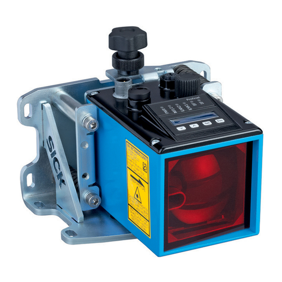
distance measuring device
Hide thumbs
Also See for DL100:
- Operating instructions manual (145 pages) ,
- Operating instructions manual (118 pages)

Related Manuals for SICK DL100


Summary of Contents for SICK DL100
- Page 1 O P E R AT I N G I N S T R U C T I O N S DL100 – EtherNet/IP Distance measuring device...
- Page 2 Changes and abbreviations of this work are prohibited without the express written agreement of SICK AG. © SICK AG • Subject to change without notice • 8016996/ZPN2/2017-09-08...
-
Page 3: Table Of Contents
Mounting notes ............... 24 6.3 Choose and mount reflector ..........24 Placement of multiple distance measuring device ....26 Place the distance measuring device towards the adjacent data transmission photoelectric switch ....27 8016996/ZPN2/2017-09-08 • © SICK AG • Subject to change without notice... - Page 4 Submenu "MF1 – Srvice" ........46 8.5.11 Submenu "Preset" – move to initialization position 47 8.5.12 Menu "MF2" ............49 8.5.13 Menu "Offset" ............50 8.5.14 Menu “SpecFu” ............50 Perform reset ................52 © SICK AG • Subject to change without notice • 8016996/ZPN2/2017-09-08...
- Page 5 Performance ................95 14.5 Supply ..................95 14.6 Inputs ..................95 14.7 Outputs ..................96 14.8 Interfaces ................96 14.9 Ambient conditions ..............96 14.10 Constructive setup ..............97 8016996/ZPN2/2017-09-08 • © SICK AG • Subject to change without notice...
- Page 6 15.1 Reflectors and reflective tape ..........98 15.1.1 Reflectors ..............98 15.1.2 Reflevtive tape............101 15.2 Connection systems ............. 101 15.3 Mounting systems..............102 15.4 Other accessories ..............103 Menu structure................104 Index ......................106 © SICK AG • Subject to change without notice • 8016996/ZPN2/2017-09-08...
- Page 7 → Voir « www.sick.com/dl100 ». ATTENTION! Tout usage de commandes, réglages ou toute application de procédures autres que ceux décrits dans ce document peut entraîner une exposition dangereuse au rayonnement. 8016996/ZPN2/2017-09-08 • © SICK AG • Subject to change without notice...
-
Page 8: General
General Information on the operating instructions These operating instructions offer important notes on handling of the dis- tance measuring devices DL100 of SICK AG. A prerequisite for safe work is compliance with all indicated safety notes and instructions. Furthermore, the local work safety regulations and general safety provi- sions applicable for the application of the distance measuring device must be complied with. -
Page 9: Explanation Of Symbols
… indicates a potentially harmful situation that may lead to property damage if not avoided. Advice and recommendations NOTE! … emphasizes useful advice and recommendations, as well as information for efficient and trouble-free operation. 8016996/ZPN2/2017-09-08 • © SICK AG • Subject to change without notice... -
Page 10: Limitations Of Liability
For quick processing of the call, keep the data of the type label, such as type code, serial number, etc. ready. EC Declaration of Conformity → The EC Declaration of Conformity can be downloaded from "www.sick.com". © SICK AG • Subject to change without notice • 8016996/ZPN2/2017-09-08... -
Page 11: Environmental Protection
Therefore: • Always observe the applicable environmental protection provisions. • Upon proper disassembly, send the disassembled components to recycling. • Separate the materials by type and recycle them. 8016996/ZPN2/2017-09-08 • © SICK AG • Subject to change without notice... -
Page 12: Safety
Distance measurement is performed by a reflector. SICK AG assumes no liability for direct or indirect loss or damage resulting from use of the product. This in particular applies for any differing use of the product that does not meet the intended purpose and that is not described or mentioned in this documentation. -
Page 13: Requirements To Skilled Persons And Operating Staff
Work safety and special danger Observe the safety notes listed here and the warnings in the other chapters of these instructions to reduce dangers to health and avoid dangerous situations. 8016996/ZPN2/2017-09-08 • © SICK AG • Subject to change without notice... -
Page 14: Warning At The Device
Operating instructions Distance measuring device DL100 – EtherNet/IP Safety Warning at the device The distance measuring device DL100 has a category 2 laser installed. The measuring device is marked with a warning. EN/IEC 60825-1:2014 Complies with 21CFR1040.10 Complies with 21 CFR 1040.10 and 1040.11 except for deviations... -
Page 15: Danger Notes And Operational Safety
Be particularly careful during mounting and alignment work. • Do not open the housing. Opening the housing will not switch off the laser. Opening the housing may increase the level of risk. • Current national regulations regarding laser protection must be observed. 8016996/ZPN2/2017-09-08 • © SICK AG • Subject to change without notice... -
Page 16: Identification
Assignment for female connector Port 1 MAC address Serial number Assignment for female connector Port 2 Assignment for supply voltage plug Icon: Distance sensor reflector mode 10 Barcode 11 Production year and month © SICK AG • Subject to change without notice • 8016996/ZPN2/2017-09-08... -
Page 17: Setup And Function
Device zero point Optical axis sender Optical axis receiver Bore for knurled screw of the optional alignment bracket Holder for optional alignment bracket Electrical connection Display and operating unit 8016996/ZPN2/2017-09-08 • © SICK AG • Subject to change without notice... -
Page 18: Function
For measurement, either the reflector or the measuring device may move linearly along the laser beam. The distance measuring device DL100 is equipped with two Ethernet interfaces. They serve communication via PROFINET IO and diagnosis and parameterization via SOPAS ET. The two interfaces have equal priorities and are internally connected to one switch. -
Page 19: Display And Operating Elements
• LED green: Ethernet present • LED orange flashing: Data transmission Interface PROFINET IO → See following table "LEDs BF and SF". Bus status → See following table "LEDs BF and SF". Table 1: LEDs 8016996/ZPN2/2017-09-08 • © SICK AG • Subject to change without notice... - Page 20 • Switch to the next lower menu level. • Save parameter change. • Confirm selection. • Leave parameter without saving. Switch to the next higher menu level. Table 5: Keys © SICK AG • Subject to change without notice • 8016996/ZPN2/2017-09-08...
-
Page 21: Display
Fig. 6: Measured value display Menu display Menu Fig. 7: Menu display NOTE! If a value or display has more than six characters, the characters are automatically displayed in sequence. 8016996/ZPN2/2017-09-08 • © SICK AG • Subject to change without notice... -
Page 22: Transport And Storage
• Initiate complaints. NOTE! Report every defect as soon as you recognize it. Damages claims can only be asserted within the applicable complaint periods. © SICK AG • Subject to change without notice • 8016996/ZPN2/2017-09-08... -
Page 23: Storage
• Storage temperature: –40 to 75 °C • Relative humidity: max. 95 %, non-condensing • At storage exceeding 3 months, regularly inspect the general condition of all components and the packaging. 8016996/ZPN2/2017-09-08 • © SICK AG • Subject to change without notice... -
Page 24: Mounting
→ See page 26, chapter 6.4. • Keep sufficient distance to data transmission photoelectric switches. → See page 27, chapter 6.5. Choose and mount reflector NOTE! → For suitable reflectors and suitable reflective tape, see page 98, chapter 15.1 © SICK AG • Subject to change without notice • 8016996/ZPN2/2017-09-08... - Page 25 Installing the reflector on highly reflective surfaces Left: Installed in driving axis, installed at the right in the lifting axis Distance measuring device Highly reflective surface Reflector Inclination of approx. 1° to 3° 8016996/ZPN2/2017-09-08 • © SICK AG • Subject to change without notice...
-
Page 26: Placement Of Multiple Distance Measuring Device
Light beams in the same direction Fig. 9: Placement of two distance measuring devices with light beams in the same light direction. Distance measuring device DL100 Reflector Minimum distance Maximum scanning range © SICK AG • Subject to change without notice • 8016996/ZPN2/2017-09-08... -
Page 27: Place The Distance Measuring Device Towards The Adjacent Data Transmission Photoelectric Switch
100 mm must be complied with at all times. The maximum scan- ning range does not influence the minimum distance. For devices of the ISD400-7xxx (ISD400 Pro) serie other minimum distances apply. Refer to operating instructions “ISD400 Pro”. Formula a ≥ 100 mm 8016996/ZPN2/2017-09-08 • © SICK AG • Subject to change without notice... -
Page 28: Align Distance Measuring Device And Reflector Against Each Other
2. Align the distance measuring device so that the light spot of the sensor hits the center of the reflector. 3. Increase the distance between the distance measuring device and the reflector. The sensor light spot must continue to hit the center of the reflector. 4. Check damping. The damping value must not exceed the value in the table. © SICK AG • Subject to change without notice • 8016996/ZPN2/2017-09-08... -
Page 29: Mount Alignment Bracket And Distance Measuring Device
→ For dimensions and item number, see page 93, chapter 14.1. Observe the following items: • Mounting notes: → see page 24, chapter 6.2. • The operation must be accessible. 8016996/ZPN2/2017-09-08 • © SICK AG • Subject to change without notice... - Page 30 3. Move distance measuring device into the alignment bracket. Fig. 13: Mount distance measuring device Knurled screw Alignment bracket Distance measuring device 4. Attach distance measuring device via the knurled screw. © SICK AG • Subject to change without notice • 8016996/ZPN2/2017-09-08...
-
Page 31: Distance Measuring Device Above Alignment Bracket
Align the distance measuring device with the alignment bracket according to the following figures. The sensor light spot must hit the center of the reflector. Alignment in X-direction Fig. 15: Align distance measuring device in X-direction using the alignment bracket Set screw to align the distance measuring device in X-direction 8016996/ZPN2/2017-09-08 • © SICK AG • Subject to change without notice... -
Page 32: Electrical Connection
Device damage or unintended operation by work under voltage! Working under voltage may cause unintended operation. Therefore: • Only perform wiring work in the powered down condition. • Line connections must only be established and disconnected with the supply voltage switched off. © SICK AG • Subject to change without notice • 8016996/ZPN2/2017-09-08... -
Page 33: Wiring Notes
Improper wiring may cause malfunctions in operation. Therefore: • Only use shielded cables with twisted pair wires. • Observe wiring notes. NOTE! → Ready-made cables, see page 101, chapter 15.2. 8016996/ZPN2/2017-09-08 • © SICK AG • Subject to change without notice... - Page 34 Operating instructions Distance measuring device DL100 – EtherNet/IP Electrical connection All electrical connections of the distance measuring device DL100 are M12 round plugs. The connection plugs of the distance measuring device are compatible to the SpeedCon™-quick connections and standard-M12 screw connections.
-
Page 35: Electrically Connect Distance Measuring Device
Cables that are strong sources of interference, such as frequency converter output cables, supply to welding plants; power cables Fig. 20: Briefly connect shield with a large area - earth both sides 8016996/ZPN2/2017-09-08 • © SICK AG • Subject to change without notice... -
Page 36: Connection Diagrams
Female connector for Ethernet Port 1 Female connector for Ethernet Port 2 not connected Connection diagrams 7.4.1 Connection diagram supply voltage Fig. 22: Connection diagram supply voltage, plug M12, 4-pin, A-coded © SICK AG • Subject to change without notice • 8016996/ZPN2/2017-09-08... -
Page 37: Connection Diagram Port 1 And Port 2 (Ethernet/Profinet Io)
Damage to the buttons by incorrect handling! Incorrect handling of the keys may damage the keys. Operation is made difficult or impossible by this. Therefore: • Only operate keys with your fingers or a pointer. • Do not operate buttons with pointed or hard objects. 8016996/ZPN2/2017-09-08 • © SICK AG • Subject to change without notice... -
Page 38: Measured Value Display
• Wait for approx. 2 minutes. The display automatically switches back to measured value display without operation of a key. Any settings made are also saved. © SICK AG • Subject to change without notice • 8016996/ZPN2/2017-09-08... -
Page 39: Change Value
Display of the pending warnings. When an error is pending, the LED PWR flashes red. When no errors are pending, no errors are displayed. → Also see page 90, chapter 12.3, list of possible errors. Table 9: Main menu 8016996/ZPN2/2017-09-08 • © SICK AG • Subject to change without notice... -
Page 40: Menu "Swvers
Main menu → → Menu → → SwVers → → HwVers Push the -key so that the parameter "HwVers" is displayed. Parameter Description HwVers Version number display Table 11: Menu "HwVers" © SICK AG • Subject to change without notice • 8016996/ZPN2/2017-09-08... -
Page 41: Menu "Profin
• The parameter is only displayed if the option "Yes" is selected for the parameter "more". Options • 0.1 • 1.0 • 10.0 • 100.0 Factory setting • 0.1 mm/s Table 12: Menu "Profin" 8016996/ZPN2/2017-09-08 • © SICK AG • Subject to change without notice... -
Page 42: Menu "More
• Enable: Multifunction input/output MF1 and multifunction output MF2 are activated. • Disable: Multifunction input/output MF1 and multifunction output MF2 are deactivated. Factory setting • Enable Table 14: Menu "MFx On" © SICK AG • Subject to change without notice • 8016996/ZPN2/2017-09-08... -
Page 43: Menu "Mf1
No further submenu is displayed for the option “LsrOff”. When the multifunction input MF1 is active, the laser is switched off. Count Counts the switching events of the multifunction input/output. The counter is reset by deactivation and activation of the distance measuring device. Table 15: Menu “MF1” 8016996/ZPN2/2017-09-08 • © SICK AG • Subject to change without notice... -
Page 44: Submenu "Mf1 - Dist
Set Hysteresis for the switching threshold Table 16: Submenu "MF1 – Dist" active inactive Limit Dist. Hyst Fig. 24: Displaying the function "Dist." Limit Distance-dependent switching threshold Hyst: Switching threshold hysteresis Dist: Measured distance © SICK AG • Subject to change without notice • 8016996/ZPN2/2017-09-08... -
Page 45: Submenu "Mf1 - Speed
• –: Once the set speed is exceeded with decreasing distance, the switching output is activated. Factory setting • + / – Table 17: Submenu "MF1 – Speed" 8016996/ZPN2/2017-09-08 • © SICK AG • Subject to change without notice... -
Page 46: Submenu "Mf1 - Srvice
Possible reasons may be incorrect measure- ments, interruption of the light beam, optical interferences or electrical interferences. Options • On • Off Factory setting • On © SICK AG • Subject to change without notice • 8016996/ZPN2/2017-09-08... -
Page 47: Submenu "Preset" - Move To Initialization Position
We recommend performing the "Preset" in standstill or at very low speeds. The maximum activation time is typically at 10000 cycles. 8016996/ZPN2/2017-09-08 • © SICK AG • Subject to change without notice... - Page 48 4. Activate the multifunction input MF1, e.g. via a proximity initiator, photo- electric sensor or switch. 5. The output value of the distance measuring device corresponds to the value set for "Preset" at the initialization position. © SICK AG • Subject to change without notice • 8016996/ZPN2/2017-09-08...
-
Page 49: Menu "Mf2
→ Also see page 44, Table 16. Submenu "MF2 – Speed" This submenu corresponds to the submenu "Speed" in the menu "MF1". → Also see page 45, Table 17. 8016996/ZPN2/2017-09-08 • © SICK AG • Subject to change without notice... -
Page 50: Menu "Offset
• Menu “more”: Option “Yes” Parameter Description AvgDst Select filter depth for the distance values. Options • Medium • Slow • Fast Factory setting • Medium Note: Medium and Slow use the same averaging depth. © SICK AG • Subject to change without notice • 8016996/ZPN2/2017-09-08... - Page 51 This menu is used to set the temperature at which the heating is to activate. The hysteresis is set firmly to 2 K. Adjustment range • -10 … +40 °C Factory setting • -10 °C Reset Perform reset → see page 52, chapter 8.6. Table 22: Menu “SpecFu” 8016996/ZPN2/2017-09-08 • © SICK AG • Subject to change without notice...
-
Page 52: Perform Reset
2. Push the key 3. The safety request "Sure?" is displayed. 4. Push the button to reset the measuring device to the delivery state. Push the key to cancel the process. © SICK AG • Subject to change without notice • 8016996/ZPN2/2017-09-08... -
Page 53: Operation Via Ethernet (Ethernet Interface)
Operation via Ethernet (Ethernet interface) Operation via Ethernet (Ethernet interface) The distance measuring device DL100 is equipped with two Ethernet interfaces. They serve communication via PROFINET IO and diagnosis and parameterization via SOPAS ET. The two interfaces have equal priorities and are internally connected to one switch. -
Page 54: User Information
"Store user information". Field "Device name" Parameter Description Name Enter optional device name for device identification. Read/Write access • Read and write Factory setting • Empty Table 27: Page "User information" – field "Device name" © SICK AG • Subject to change without notice • 8016996/ZPN2/2017-09-08... -
Page 55: Measurement Values
Click the button "Auto-Scale Y" to adjust the display to the current measurement values. Read/Write access • Read and write Unit • m Table 30: Page "Measured data" – field "Distance value" 8016996/ZPN2/2017-09-08 • © SICK AG • Subject to change without notice... -
Page 56: Diagnostic Data
Display of current errors: Laser, temperature, level and plausi- bility Read/Write access • Read only Level Display of the current reception level (damping value) Read/Write access • Read only © SICK AG • Subject to change without notice • 8016996/ZPN2/2017-09-08... -
Page 57: Parameter Settings
Specify present value for the distance measurement value. Read/Write access • Read and write Input value • –300000 ... 300000 Unit • mm Factory setting • 0 Table 33: Page "Parameter settings" – field "General settings" 8016996/ZPN2/2017-09-08 • © SICK AG • Subject to change without notice... - Page 58 Activate and deactivate multifunction input and output MF1 and multifunction output MF2. Read/Write access • Read and write Input value • 0: off / 1: on Factory setting • On Table 36: Page "Parameter settings" – field "MF1/MF2 activation" © SICK AG • Subject to change without notice • 8016996/ZPN2/2017-09-08...
- Page 59 MF1. Read/Write access • Read and write Input value • 0: high / 1: low Factory setting • Low Table 37: Page “Parameter settings” – field “MF1 Function configuration” 8016996/ZPN2/2017-09-08 • © SICK AG • Subject to change without notice...
- Page 60 Threshold Enter switching threshold for the multifunction output MF1. velocity Read/Write access • Read and write Input value • 0 ... 15000 Unit • mm/s Factory setting • 5000 © SICK AG • Subject to change without notice • 8016996/ZPN2/2017-09-08...
- Page 61 • The warning messages "Measurement stability", "Level", "Laser", "Temperature" and "Device not ready" are activated. The message "Heater state" is deactivated. Table 40: Page "Parameter settings" – field "MF1, Service configuration" 8016996/ZPN2/2017-09-08 • © SICK AG • Subject to change without notice...
- Page 62 You may reset the counters via the button "Reset MF2". Read/Write access • Read and write Input value • –2147483648 ... 2147483647 Table 42: Page "Parameter settings" – field "Number MF activation" © SICK AG • Subject to change without notice • 8016996/ZPN2/2017-09-08...
- Page 63 Enter power up threshold for heating. Read/Write access • Read and write Input value • –10 ... +40 Unit • °C Factory setting • –10 Table 44: Page "Parameter settings" – field "Heater" 8016996/ZPN2/2017-09-08 • © SICK AG • Subject to change without notice...
- Page 64 Click the button "Parameter Reset" to reset the parameters to factory settings. Reset Read/Write access • Write only Table 46: Page "Parameter settings" – field "Set parameters to default values" © SICK AG • Subject to change without notice • 8016996/ZPN2/2017-09-08...
-
Page 65: Methods
• Use the selection button to select the desired option. • Click the button to perform the option. Read/Write access • Write only Input value • 0: Off / 1: On / 2: Auto Factory setting • Auto Table 47: Page "Methods" 8016996/ZPN2/2017-09-08 • © SICK AG • Subject to change without notice... -
Page 66: Ethernet/Ip-Interface
Explicit write of an attribute within the position sensor object ........82 2.1.6. Apply a static preset ....................83 2.1.1. EIPScan .......................... 84 2.2. Explicit Messaging and dynamic preset ............... 84 2.2.1. Explicit Messaging – Configuration Assembly .............. 87 2.2.1. © SICK AG • Subject to change without notice • 8016996/ZPN2/2017-09-08... -
Page 67: Interface Description
Baud rates 10 and 100 MBit/s • Data transport layer Ethernet II, IEEE 802.3 • ACD supported • DLR (ring topology) supported • Integrated switch supported • Reset services supported © SICK AG • Subject to change without notice • 8016996/ZPN2/2017-09-08... -
Page 68: Position Sensor Object
MF2 Service - Plausib. WE BOOL MF2 Service - Temp. WE BOOL MF2 Service - Level WE BOOL MF2 Service - Laser WE BOOL MF2 Service - Not Ready BOOL © SICK AG • Subject to change without notice • 8016996/ZPN2/2017-09-08... - Page 69 Serial Number SHORT_ Identification STRING Product Code SHORT_ STRING HW Version SHORT_ STRING FPGA Version SHORT_ STRING uC1 Version SHORT_ STRING uC2 Version SHORT_ STRING Table 1 Position Sensor Object © SICK AG • Subject to change without notice • 8016996/ZPN2/2017-09-08...
-
Page 70: Position Sensor Object In Detail
15. Thus, if attribute 15 is set to 0x0801 (1/10mm), a value of 10 equals a preset to 1mm. Velocity Value DINT Velocity measured by DL100. The velocity format is determined by attribute 25/26. Velocity Format ENGUNIT... - Page 71 Dynamic Preset, referenced by output assembly 0x80. Writing 0x800000A presets the distance value to 10. In case attribute 15 is set to 0x0801 (1/10mm), a value of 10 equals a preset to 1mm. © SICK AG • Subject to change without notice • 8016996/ZPN2/2017-09-08...
- Page 72 If disabled, bit is not considered when attribute 121 is set to OUTPUT_SERVICE. MF1 Setup BOOL Heater active Service Disabled (0, default), Enabled (1): If disabled, bit is not considered when attribute 121 is set to OUTPUT_SERVICE. © SICK AG • Subject to change without notice • 8016996/ZPN2/2017-09-08...
- Page 73 MF2 Setup UDINT Range: 1mm – 300m Hysteresis MF2 Setup DINT Range: 50mm/s – …mm/s Threshold Velocity MF2 Setup USINT Threshold velocity can be exceeded in one or both directions. © SICK AG • Subject to change without notice • 8016996/ZPN2/2017-09-08...
-
Page 74: Explicit Messaging
UDP (Unicast and Multicast are supported). The device supports one I/O Connection. The data transferred between scanner and slave is structured within an input, an output and a configuration assembly. Each assembly is formed by attributes defined by the position sensor object. © SICK AG • Subject to change without notice • 8016996/ZPN2/2017-09-08... -
Page 75: Input Assemblies
BOOL MF1 Output – Threshold Pos. DINT MF1 Output – Hyst. Pos. UDINT MF1 Output – Threshold Velo. MF1 Output – Velocity Sign USINT MF1 Input - Preset DINT © SICK AG • Subject to change without notice • 8016996/ZPN2/2017-09-08... - Page 76 MF2 Output - Threshold Velo. MF2 Output - Velocity Sign USINT Avg. Filter Distance USINT Avg. Filter Velocity USINT Error Rejection USINT Heating Threshold SINT Frequency Mode SINT Reserved BYTE © SICK AG • Subject to change without notice • 8016996/ZPN2/2017-09-08...
-
Page 77: Examples
Note: Under Windows 7 you must run the program as administrator. 2.1.1. Tool configuration Click on “Options” and select the Ethernet Adapter that is connected to a DL100. The default network configuration of the device is: 192.168.100.236 Subnet: 255.255.255.0... -
Page 78: Scan For Ethernet/Ip Slaves
2.1.2. Scan for EtherNet/IP Slaves • Go to tab “List Identity” • Choose “Broadcast” • Click “Send List….over UDP” • Device will show up • Mark the device to display more information © SICK AG • Subject to change without notice • 8016996/ZPN2/2017-09-08... -
Page 79: Configure The Device For Dhcp / Bootp Or Static Ip
Go to the TCP/IP tab • Click “Get_Attribute_ALL” • Apply changes to …. • Changes become effective after reboot (Power Cycle or via Reset Service) Static IP configuration Switch between static dynamic assignment © SICK AG • Subject to change without notice • 8016996/ZPN2/2017-09-08... -
Page 80: Physical Layer Configuration
If auto-negotiate is turned on the device will ignore all other parameters within attribute o Forced Duplex Mode 0 => half duplex, 1=> full duplex o Forced Interface Speed can be set 10 and 100. © SICK AG • Subject to change without notice • 8016996/ZPN2/2017-09-08... -
Page 81: Explicit Read Of An Attribute Within The Position Sensor Object
Choose for instance attribute 10 (Position Value Signed) • Send Request • Position value is stored within the last four bytes of the reply (change endianess!) • 0xD5070000 => 0x000007d5 => 2005 © SICK AG • Subject to change without notice • 8016996/ZPN2/2017-09-08... -
Page 82: Explicit Write Of An Attribute Within The Position Sensor Object
• Go to the previous section an observe that the position value changed to 0xC8 => 200. This is expected as the resolution was changed from 1/10mm to 1mm. © SICK AG • Subject to change without notice • 8016996/ZPN2/2017-09-08... -
Page 83: Apply A Static Preset
Write 0x01 to attribute 106 to reset this preset Note: Attribute 106 monitors 0-1 transitions. Thus, you might need to write 0x00 in case you have previously written 0x01. © SICK AG • Subject to change without notice • 8016996/ZPN2/2017-09-08... -
Page 84: Eipscan
2.2.1. Explicit Messaging and dynamic preset • Click “Add new device” within the “Device / IO Module” menu • Add Class 1 connection, configure it and click “OK” © SICK AG • Subject to change without notice • 8016996/ZPN2/2017-09-08... - Page 85 Operating instructions Distance measuring device DL100 – EtherNet/IP Position Value Signed =200mm Input Assembly Output Assembly © SICK AG • Subject to change without notice • 8016996/ZPN2/2017-09-08...
- Page 86 Operating instructions Distance measuring device DL100 – EtherNet/IP Position Value Signed =1000mm Apply preset value Position Value Signed =200mm reset preset value © SICK AG • Subject to change without notice • 8016996/ZPN2/2017-09-08...
-
Page 87: Explicit Messaging - Configuration Assembly
(uwe.kuehnle@sick.de). Simply select the configuration options and click on “Generate”. The resulting string can be copied and pasted to EIPScan. Note: The tool does not comply with SICK software standards. It is a rudimentary tool that was written to help us debugging the device. -
Page 88: Cleaning And Maintenance
General interferences are not displayed. When a warning is pending, the LED PWR flashes orange. A measurement value is output When an error is pending, the LED PWR flashes red. The measurement value "0" is output. © SICK AG • Subject to change without notice • 8016996/ZPN2/2017-09-08... -
Page 89: Led Status Indicators
For alignment and mounting, see page 24, chapter 6. wLaser The measurement laser is still operational Keep replacement device ready. but at the end of its service life. 8016996/ZPN2/2017-09-08 • © SICK AG • Subject to change without notice... -
Page 90: Error Messages
• Use device with heating at low ambient temperatures. • Use cooling housings for high ambient temperatures. Table 51: Error messages © SICK AG • Subject to change without notice • 8016996/ZPN2/2017-09-08... -
Page 91: Profinet Io Error Messages
The internal devicetemperature is within the Check ambient temperature. threshold range. → For the permissible am- bient temperature, see page 106, chapter 14.8. Table 52: PROFINET IO error messages 8016996/ZPN2/2017-09-08 • © SICK AG • Subject to change without notice... -
Page 92: Return
• Dispose of the distance measuring device according to the respective country-specific provisions. 13 Repair Repairs must only be performed by the manufacturer. The manufacturer's warranty will lapse in case of interruptions and changes to the device. © SICK AG • Subject to change without notice • 8016996/ZPN2/2017-09-08... -
Page 93: Technical Data
All dimensions in mm (inch) Fig. 25: Dimensions distance measuring device DL100 Optical axis sender Optical axis receiver Device zero point Threaded mounting hole M5 LED "Status" Display Operating elements 8016996/ZPN2/2017-09-08 • © SICK AG • Subject to change without notice... -
Page 94: Device Selection Ethernet/Ip-Interface
"www.sick.com/dl100". 14.3 Laser/optics Light source Laser diode, red light Laser protection class 2 pursuant to EN 60825-1 /CDRH CW modulation ± 0.85 Po sine-shape modulated Maximum output ≤ 1.9 mW Pulse duration 6.8 ns © SICK AG • Subject to change without notice • 8016996/ZPN2/2017-09-08... -
Page 95: Performance
Multifunction input MF1, adjustable • Hi > 12 V • Lo < 3 V → See page 43, Table 15, parameter “ActSta”. Protective circuit No, not reverse polarity protected Table 57: Inputs 8016996/ZPN2/2017-09-08 • © SICK AG • Subject to change without notice... -
Page 96: Outputs
Maximum acceleration change 10 m/s² Vibration resistance (sine) EN60068-2-6 Noise EN60068-2-64 Shock resistance EN 60086-2-27 1) When used in the household area, the device may cause interferences. Table 60: Ambient conditions © SICK AG • Subject to change without notice • 8016996/ZPN2/2017-09-08... -
Page 97: Constructive Setup
• Casing: Cast aluminium GD-AlSi12Cu1 (3.2982.05) • Front screen: PMMA Connections M12, SpeedCon™ Display • 6 points with a 5 x 7 point matrix • Overflow is displayed with the maximum value that can be displayed, –99999 bzw. 999999. Table 61: Constructive setup 8016996/ZPN2/2017-09-08 • © SICK AG • Subject to change without notice... -
Page 98: Accessories
Only some of the available accessories are shown here. Complete details on all accessories are available at www.sick.com/dl100 15.1 Reflectors and reflective tape 15.1.1 Reflectors Fig. 26: Reflector 0.3 x 0.3 m² Diamond Grade, mounted Description Reflector 0.3 x 0.3 m² Diamond Grade, mounted on base plate ALMG3 Type PL240DG Part no. 1017910 © SICK AG • Subject to change without notice • 8016996/ZPN2/2017-09-08... - Page 99 Fig. 27: Reflector 0.6 x 0.6 m² Diamond Grade, mounted Description Reflector 0.6 x 0.6 m² Diamond Grade, mounted on base plate ALMG3 Type PL560DG Part no. 1016806 Fig. 28: Reflector 1.0 x 1.0 m² Diamond Grade, mounted Description Reflector 1.0 x 1.0 m² Diamond Grade, mounted on base plate ALMG3 Type PL880DG Part no. 1018975 8016996/ZPN2/2017-09-08 • © SICK AG • Subject to change without notice...
- Page 100 Silicon wire 2 m, 3 x 0.75 mm , open ending Fig. 30: Reflector 0.6 x 0.6 m² Diamond Grade, mounted, including heating Description Reflector 0.6 x 0.6 m² Diamond Grade, mounted, on base plate ALMG3, including controlled heating +20 °C, 230 V AC, 200 W, IP 64 Type PL560DG-H Part no. 1023888 © SICK AG • Subject to change without notice • 8016996/ZPN2/2017-09-08...
-
Page 101: Reflevtive Tape
Fig. 31: "Diamond grade" reflective tape Description "Diamond grade" reflective tape, size customizable Type REF-DG Part no. 4019634 Description "Diamond grade" reflective tape, curve 749 x 914 mm Type REF-DG Part no. 5320565 15.2 Connection systems Note! Complete details on all accessories are available at www.sick.com/dl100 8016996/ZPN2/2017-09-08 • © SICK AG • Subject to change without notice... -
Page 102: Mounting Systems
Ø 5.4 (0.21) 137 (5.39) 85.3 (3.36) (4.96) All dimensions in mm (inch) Fig. 32: Alignment bracket Description Alignment bracket Type BEF-AH-DX100 Part no. 2058653 Material: Zinc-plated steel sheet © SICK AG • Subject to change without notice • 8016996/ZPN2/2017-09-08... -
Page 103: Other Accessories
Description Cooling Casing Type TPCC-Dx100 Part no. 6048328 Material Glass-fiber reinforced plastic (GFK) Operating ambience temperature –20 … +75 °C (short-term +80 °C) Supply voltage 24 V DC ± 20 % Current consumption 15 A at 24 V DC Enclosure rating IP 54 8016996/ZPN2/2017-09-08 • © SICK AG • Subject to change without notice... -
Page 104: Menu Structure
LsrOff Preset Choose option Speed Display only Menu depending on selection of Functn siehe ActSta Functn Count Dist Speed Srvice Choose option Display only * * Display as ticker © SICK AG • Subject to change without notice • 8016996/ZPN2/2017-09-08... - Page 105 Choose option Choose option Enter value Enter value Enter value Srvice WrnLsr WrnLvl WrnTemp WrnPlb NotRdy Heat Choose option Choose option Choose option Choose option Choose option Choose option 8016996/ZPN2/2017-09-08 • © SICK AG • Subject to change without notice...
-
Page 106: Index
At measuring device ..........37 Factory settings ............. 52 Change value ............38 Function ................. 18 Choose option ............38 Choose parameter ........... 38 Via Ethernet ............. 53 General ................8 © SICK AG • Subject to change without notice • 8016996/ZPN2/2017-09-08... - Page 107 Device information ..........53 Device name ............54 Diagnostic data ............56 Distance value ............55 Function configuration ..........62 General settings ............57 Hardware version............. 54 Heater ............... 63 8016996/ZPN2/2017-09-08 • © SICK AG • Subject to change without notice...
- Page 108 Phone +852 2153 6300 Phone +421 482 901201 E-Mail ghk@sick.com.hk E-Mail mail@sick-sk.sk Hungary Slovenia Phone +36 1 371 2680 Phone +386 591 788 49 E-Mail office@sick.hu E-Mail office@sick.si India South Africa Phone +91 22 6119 8900 Phone +27 11 472 3733 Further locations at www.sick.com E-Mail info@sick-india.com E-Mail info@sickautomation.co.za SICK AG | Waldkirch | Germany | www.sick.com...
Need help?
Do you have a question about the DL100 and is the answer not in the manual?
Questions and answers