Table of Contents
Advertisement
Quick Links
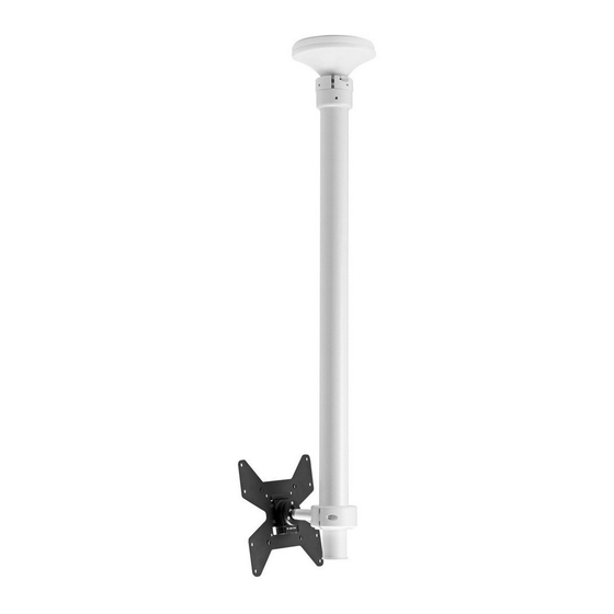
1040 Ceiling Mount
B
Mounting Plate
F
Coach
Screw
(x4)
A
Pole
Assembly
L
Security
Screw
IMPORTANT INFORMATION
! Please ensure this product is installed as per these installation instructions.
! The manufacturer accepts no responsibility for incorrect installation.
! The maximum pole capacity defines the weight capacity of the complete mounting solution, not individual
display mounts.
! Failure to mount this product correctly may cause serious injury/death during or following installation.
! This product is not suitable for outdoor use.
! Do not use this product for mobile applications.
! This product should only be installed by professional installers of good mechanical aptitude, who have experience with
building construction, and fully understand these instructions and the consequences of incorrect installation.
! Ceiling Mount only achieves maximum weight rating when appropriately fastened to a ceiling of adequate
structural capacity.
! Professional installer to ensure adequate structural capacity of ceiling (including appropriate safety factor) to support
total weight of all equipment being mounted.
! Drilling into electrical wires can cause death - use appropriate equipment and caution when drilling holes in ceilings to
avoid electrical cables, water pipes and gas pipes. Do not drill into structures unless established it's safe to do so.
C
Mounting Plate
Cover
G
H
2.5mm/3mm/
Nylon
5mm Hex
Anchor
Keys
(x4)
M
N
Set
M4x16mm
M5x16mm
Screw
M4x25mm
M5x25mm
(x4 each)
(x4 each)
D
False Ceiling
VESA Plate
Cover
I
J
M4/M5/M10
M4/M5
M6/M8
Washer
Spacer
Spacer
(x4 each)
(x4)
O
P
M6x16mm
M8x16mm
M6x30mm
M8x30mm
(x4 each)
(x4 each)
Installation Guide
TH-1040-CTS
TH-1040-CTL
TH-1040-CT-B2B
TH-1040-CT-RCK
TH-1040-CT-DV
REQUIRED TOOLS
E
• Power drill
• 7mm Drill Bit
• 12mm Masonry Drill Bit
• Phillips head screw driver
• 17mm Socket Wrench or
K
Shifter
(x4)
Q
Maximum pole capacity
0 - 50kg
(0 - 110lb)
TH-1040-CT Page 1 of 6
Advertisement
Table of Contents

Related Manuals for Atdec TH-1040-CTS


Summary of Contents for Atdec TH-1040-CTS
- Page 1 Installation Guide TH-1040-CTS TH-1040-CTL 1040 Ceiling Mount TH-1040-CT-B2B TH-1040-CT-RCK TH-1040-CT-DV COMPONENT CHECKLIST REQUIRED TOOLS Mounting Plate Mounting Plate False Ceiling VESA Plate Cover Cover • Power drill • 7mm Drill Bit • 12mm Masonry Drill Bit • Phillips head screw driver •...
- Page 2 1. Install Mounting Plate • Use Mounting Plate B as a template to mark hole positions. Masonry Ceiling Timber Ceiling • Use a suitable power drill to drill Ø7x70mm holes for timber joist installations or Ø12x70mm for concrete. • Please choose fasteners that will suit your installation, consult a qualified engineer prior to installing.
- Page 3 5.3. Tighten the socket cap 5.4. If necessary, use the set screws on either side of the screws (x2) to set the height. pole joint to correct the alignment of the lower pole. 2.5mm Hex Key TIGHTEN FIRMLY Pole Joint Set Screw 6. Attach VESA Plate to display NOTE: • Always use a washer. •...
- Page 4 9. (OPTIONAL) Install False Ceiling Cover If the Lower Pole hangs CLICK below a suspended ceiling, clip the False Ceiling Cover over the Lower Pole, and PUSH push up to the ceiling. False Ceiling Cover Lower Pole ADJUSTMENTS Display Height G - 5mm Hex Key G - 5mm Hex Key G - 5mm Hex Key Socket Cap Screw Socket Cap Screw...
- Page 5 1040 Ceiling Tilt Accessories Installation Guide TH-1040-CT-B2B TH-1040-CT-RCK TH-1040-CT-DV COMPONENT CHECKLIST 1040 Ceiling Back to Back Kit Security M4 Washer Screw M5 Washer (optional) (x4 each) WEIGHT RANGE Maximum pole capacity 0 - 50kg (0 - 110lb) M4/5 M6/8 M4x16mm M5x16mm Spacer Spacer...
- Page 6 Socket Cap Screw the Socket Cap Screws (x2). Mount Head Tighten screws Accessory firmly and equally. 2.2 Refer to TH-1040-CTS/ TH-1040-CTL Installation Socket Cap Screw Instructions, Step 6. Attach VESA plate to display. TH-1040-CT-RCK 1040 Ceiling Rear Collar Kit 1. Replace Back of Existing Mount Head 1.1 Remove back half of the...
Need help?
Do you have a question about the TH-1040-CTS and is the answer not in the manual?
Questions and answers