
Related Manuals for Wren Wall unit


Summary of Contents for Wren Wall unit
- Page 1 WALL UNIT 600 - 800 Lift Assembly Guide 288 x 600 288 x 800 360 x 600 360 x 800 For Internal Use: FI.WR.INS.032_WKIN00121_WALL_600-800_Lift_Rev4.indd...
-
Page 2: Assembly Guide
WALL UNIT BEFORE YOU START 600 - 800 Lift INSTALLATION Assembly Guide SHOULD BE PERFORMED BY A COMPETENT PERSON ONLY. THIS PRODUCT COULD BE DANGEROUS IF INCORRECTLY INSTALLED Panel A Panel C Frontal Panel B (packed separately) x1 Back Panel... - Page 3 WALL UNIT 600 - 800 Lift Step 1. Seat dowel (F) Assembly Guide into holes in end panel (B) as shown. Seat (G) cam dowel into hole as shown. Step 2. Seat cam dowel (G) into holes in end panel (B) as shown.
- Page 4 WALL UNIT Step 6. 600 - 800 Lift Seat dowel (F) into holes in Assembly Guide both panels (B) as shown. Seat (G) cam dowel Step 7. into hole as Seat cam dowel shown. (G) into holes in both end panels (B) as shown.
- Page 5 WALL UNIT 600 - 800 Lift Assembly Guide Step 10. Ensure carcass is square. Step 11. Slide the back panel clips (T) into the groove of both panels (B) & (C). The back panel clips (T) should be evenly spaced as shown and positioned to allow the hanging bracket and corner gussets to be fitted.
- Page 6 180 degrees 2 x 20mm screws (S) per bracket Step 13. Secure corner gussets to the bottom left and right hand side of the wall unit using 4 x 15mm screws (L) per plate. Detail B Detail B View though Back Panel Step 14.
- Page 7 WALL UNIT 600 - 800 Lift Step 15. Measure and attach Hinge Mounting Plate onto fixed shelf (C) as shown, Assembly Guide using screws which are already positioned within the Hinge Plates. Left Right Front Front Hinge Plates TOP FIXED SHELF Step 16.
- Page 8 WALL UNIT Step 20. Measure appropriately and attach the 2 x hanging bracket plates onto the 600 - 800 Lift wall screwing through the provided holes into your wall. Assembly Guide Screws for fixing to walls are not provided as these vary depending on your wall material and construction.
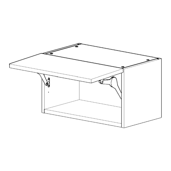
- Page 9 WALL UNIT Step 24. Clip hinges into hinge mounting plates on 600 - 800 Lift the unit. Assembly Guide Step 25. Clip lift hinge mechanisms into each bracket. Step 26. Use a 4mm allen key to adjust the strength of the lift hinge for the door weight.
- Page 10 WALL UNIT 600 - 800 Lift Assembly Guide...
- Page 11 WALL UNIT 600 - 800 Lift Assembly Guide...
Need help?
Do you have a question about the Wall unit and is the answer not in the manual?
Questions and answers