Salda SMARTY RV Mounting And Installation Instruction
Source: salda.lt/en, vetter-lufttechnik.de
Table of Contents
Advertisement
Quick Links
Advertisement
Table of Contents

Related Manuals for Salda SMARTY RV


Summary of Contents for Salda SMARTY RV
- Page 1 SMARTY RV MOUNTING AND INSTALLATION INSTRUCTION...
-
Page 2: Table Of Contents
8.1.3. EXTERNAL SWITCHES 8.1.4. CONNECTION OF REMOTE CONTROL PANEL OR MODBUS 8.1.5. “MCB TOOL” PROGRAM DESCRIPTION 9. POSSIBLE FAULTS AND TROUBLESHOOTING 10. ECODESIGN DATA TABLE 11. DECLARATION OF CONFOMITY 12. WARRANTY 12.1. LIMITED WARRANTY COUPON | EN SMARTY RV v2021.1... -
Page 3: Symbols And Marking
ODA - outdoor air; SUP - supply air; ETA - extract air; EHA - exhaust air. Figure. 2.3. Technical label location and air duct indication (left side) Figure. 2.4. Technical label location and air duct indication (right side) NOTE. Ducts, cooker hood are not the part of the unit. SMARTY RV v2021.1 EN |... -
Page 4: Safety Instructions And Precautions
• manually check fans to make sure they are not stuck or blocked; • if rotary heat exchanger is installed in the device, make sure that it is not stuck or blocked; • check the earthling; • | EN SMARTY RV v2021.1... -
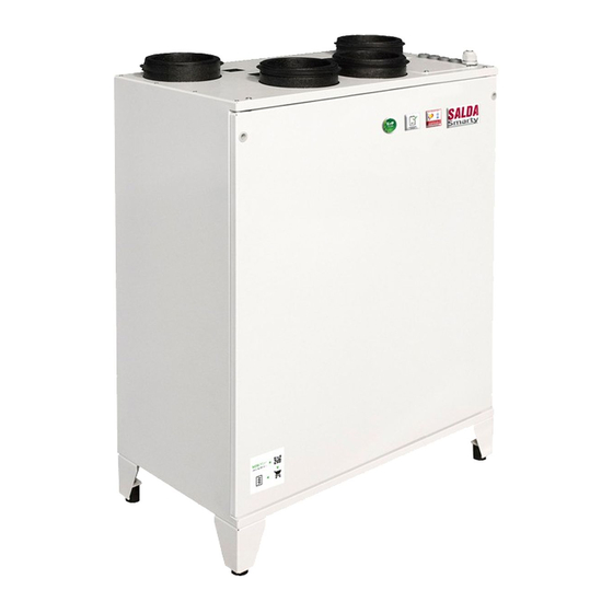
Page 5: Information About The Product
4. INFORMATION ABOUT THE PRODUCT 4.1. DESCRIPTION standard package. Not suitable for operation in pools, saunas and other similar premises. 4.2. DIMENSIONS AND WEIGHT SMARTY RV v2021.1 EN |... -
Page 6: Technical Data
Integrated electrical heater [kW/A] 0,6/2,6 0,6/2,6 [kW/A] 0,75/3,91 0,77/4,13 Integrated control board [mm] [mm] [mm] Device protection class IP 34 IP 34 According to EN 13141-7. Not suitable for installation in living rooms: additional noise insulation required. | EN SMARTY RV v2021.1... -
Page 7: Operating Conditions
605 mm 605 mm Sealing rubber 15x8, 44057658 649 mm 649 mm Bracket 16801003 Bracket 19751501 4.6. DESCRIPTION OF COMPONENTS Figure 4.6.1. Smarty 2R VEL construction Figure 4.6.2. Smarty 2R VER plus construction - Rotor motor. SMARTY RV v2021.1 EN |... -
Page 8: Instalation
SMARTY [mm] [mm] [mm] [units] 2 RV 2030 1200 2 RV plus 2030 1200 Figure 5.2.1. In order to prevent damage to the casing, only a product placed on a pallet should be lifted. | EN SMARTY RV v2021.1... -
Page 9: Unpacking
5.4. PIPING AND INSTRUMENTATION DIAGRAM Figure 5.4.1. Smarty RV (* Only heater or preheater can be connected at a time; ** Only one sensor can be used at a time) SMARTY RV v2021.1 EN |... -
Page 10: Mounting
5.6. UNIT PLACING AND MOUNTING POSITIONING REQUIREMENTS 1,5xL Figure 5.6.1. Min. distance to open the door - 1,5xL; Min. distance to open the control box door - H > 400 mm. | EN SMARTY RV v2021.1... -
Page 11: Wall-Mounting Of The Unit
• If you have any questions regarding the safe installation and use of the product, please contact the manufacturer or its representative. • insulating ring. • • Carefully remove the lid covering the electric connection intended for the connection of an electrical part of the kitchen hood and the ventilation unit. SMARTY RV v2021.1 EN |... -
Page 12: Front Cover (Accessory) Installation
The manufacturer does not assume any liability for personal injuries and property damage due to nonconformance with the provided instructions. 5.10. START-UP RECOMMENDATIONS 5.10.1. SYSTEM PROTECTION tions: F1, F2 - 1A(5x20) MCB protection; | EN SMARTY RV v2021.1... - Page 13 • cable connection to MCB • all electrical equipment protection components are properly connected (if they are additionally used), • earthling and protection systems are properly installed, • condition of all seals and sealing surfaces is proper. SMARTY RV v2021.1 EN |...
-
Page 14: Maintenance
Check the tightness of connections Clean ing unit (contactor), i.e. make sure that its casing has no signs produce any unusual sounds. All the contactors in the product or in its accessories must be checked. 6.3. COVER OPENING | EN SMARTY RV v2021.1... -
Page 15: Filters Maintenance
FILTERS MAINTENANCE • • Figure 6.4.1. Smarty 2R VE Figure 6.4.2. Smarty 2R VE plus manual or on our website www.salda.lt 6.5. ROTOR MAINTENANCE • Maintenance of rotor heat exchanger must be performed on annual basis, once per year. •... -
Page 16: Heater Maintenance
Figure 6.6.2. Smarty 2R VE plus 6.7. HEATER MAINTENANCE • • • • • If necessary, electric heater can be removed. Disconnect the electrical connector from the heater and remove the heater. Smarty 2R VE | EN SMARTY RV v2021.1... -
Page 17: Control Board Maintenance
Smarty 2R VE plus 6.8. CONTROL BOARD MAINTENANCE • • • SMARTY RV v2021.1 EN |... -
Page 18: Control
SALDA AIR mobile application ST-SA-Control BMS over Modbus TCP/IP BMS over BACnet TCP/IP 7.2. DEVICE FUNCTIONS application and SALDA AIR mobile application. For unit control instructions, refer to the operation manual of the existing control device. | EN SMARTY RV v2021.1... -
Page 19: Accessories
S-RCO2-F2 ACC000278 ACC000278 Sensor humidity duct S-KFF-U ACC000279 ACC000279 External sensors Sensor humidity room S-RFF-U-D-F2 ACC000280 ACC000280 Temperature sensor TJ1TE-NTC10K3B4.5 ACC002560 ACC002560 Smoke detector UG-3-A4O ACC004464 ACC004464 Actuators ACC000305 ACC000305 Dampers SKG-A 125 FIT000201 FIT000201 SMARTY RV v2021.1 EN |... -
Page 20: Connection Of Accessories
1. Set that extract air RH converter is connected as 0-10 V input “SERVICE › SENSORS › 0-10 VDC SENSORS › AIR QUALITY SENSOR 1” (choose “Extract RH”) 2. Set: 3. You can see the level of extract air RH in the tab “ADJUSTER › MONITORING › EXTRACT AIR RH” | EN SMARTY RV v2021.1... - Page 21 60 cm max. 400m If the duct CO transmitter is used, it must be installed in the extract air duct. To install duct transmitters, hole drilling tools are required . 8.1.4. CONCENTRATION ACCORDING TO PETTENKOFER LIMIT SMARTY RV v2021.1 EN |...
-
Page 22: Connection Of Supply And Extract Air Dampers
• Pressure compensation after steam extraction – KEFA KF2EDGKD-2.5/8P X4 connector, contacts; 8.1.7. CONNECTION OF REMOTE CONTROL PANEL OR MODBUS SL1 DIP switch Purpose (ON position) 120R line termination resistor 1kR connection line pull-up resistor resistor 8.1.8. “MCB TOOL” PROGRAM DESCRIPTION | EN SMARTY RV v2021.1... - Page 23 1. Choose connection type Connection status Set Modbus slave ID Select connection type Select COM port of RS485 converter Press to connect 2. Connect to device (press “CONNECT” button) Press to disconnect from device SMARTY RV v2021.1 EN |...
- Page 24 8.1.9. RECOMMENDED SCHEME FOR CONNECTION OF INTERNAL AND EXTERNAL COMPONENTS Fans (SP46) | EN SMARTY RV v2021.1...
- Page 25 Smarty RV control board (219.0161.0.1.1-PS) SMARTY RV v2021.1 EN |...
- Page 26 Smarty RV control board (219.0161.0.1.2-PS) | EN SMARTY RV v2021.1...
- Page 27 Smarty RV control board (219.0161.0.1.3-PS) SMARTY RV v2021.1 EN |...
- Page 28 Smarty RV control board (219.0161.0.1.4-PS) | EN SMARTY RV v2021.1...
- Page 29 SMARTY RV v2021.1 EN |...
- Page 30 | EN SMARTY RV v2021.1...
- Page 31 SMARTY RV v2021.1 EN |...
- Page 32 Rotor motor (5.0013.0.1.0-PS) Inductive sensor (5.0014.0.1.0-PS) | EN SMARTY RV v2021.1...
-
Page 33: Possible Faults And Troubleshooting
Inspect the rotor belt. If it is broken then it Rotor is not rotating Rotor belt is broken If belt is not broken, check its tightness and Rotor belt failure Rotor belt is slipping adjust, if necessary. SMARTY RV v2021.1 EN |... -
Page 34: Ecodesign Data Table
[ W ] [ dB(A) ] /s ] 0,039 [ Pa ] [ W/(m /h) ] 0,47 Declared maximum internal leakage rates Declared maximum external leakage rates Timer ErP Compliance 2018 Internet address for disassembly instructions | EN SMARTY RV v2021.1... - Page 35 [ W ] [ dB(A) ] /s ] 0,05 [ Pa ] [ W/(m /h) ] 0,47 Declared maximum internal leakage rates Declared maximum external leakage rates Timer ErP Compliance 2018 Internet address for disassembly instructions SMARTY RV v2021.1 EN |...
-
Page 36: Declaration Of Confomity
EN IEC 61000-6-1:2019-03 - Electromagnetic compatibility (EMC) -- Part 6-1: Generic standards - Immunity for residential, commercial and light- industrial environments. LST EN 61000-6-3:2008 - Electromagnetic compatibility (EMC) -- Part 6-3: Generic standards - Emission standard for residential, commercial and light-industrial environments. Quality: ISO 9001:2015. Date 2020-10-23 Giedrius Taujenis Director product development | EN SMARTY RV v2021.1... -
Page 37: Warranty
24 months* ..................................*Refer to the WARRANTY CONDITIONS technical and operational characteristics of the Products. other technical documents of the product carefully. The number of the Limited Warranty Coupon and serial number of the product SMARTY RV v2021.1 EN |... - Page 38 SMARTY RV v2021.1...
- Page 39 SMARTY RV v2021.1...
- Page 40 Once per year** Every 3-4 Filter replacement months** * - Look at the product label. ** - At least. NOTE. MANUALS IN OTHER LANGUAGES smartyrvlt smartyrvru smartyrvpl smartyrvde MAN000304 Ragainės g. 100 +370 41 540 415 Šiauliai LT-78109, LITHUANIA office@salda.lt...
Need help?
Do you have a question about the SMARTY RV and is the answer not in the manual?
Questions and answers