Salda Smarty 2R VE Manual
Source: salda.lt/en, vetter-lufttechnik.de
Hide thumbs
Also See for Smarty 2R VE:
- User and service technical manual (48 pages) ,
- Mounting and installation instruction (36 pages)

Related Manuals for Salda Smarty 2R VE


Summary of Contents for Salda Smarty 2R VE
- Page 1 AHU WITH HEAT RECOVERY Smarty 2R VE User and service technical manual Subject to technical modification Smarty 2R VE_P0108_AZ_0002...
- Page 2 Smarty 2R VE Symbols components (aut. Smarty 2RVER-MCB.0-1k) Marking The principal connection scheme of internal and external Transportation and storage components Unpacking The principal connection scheme of internal and external Standard package of components components Description The principal connection scheme of internal and external...
- Page 3 200003025238 Smarty 2R VE PAVADINIMAS 0.084 kW; 0.92 A; 230/50 V/Hz; ~1 0.085 kW; 0.93 A; 230/50 V/Hz; ~1 0 V/Hz; ~0 0 V/Hz; ~0 0.005 kW; 0.021 A; 24/50 V/Hz; ~- Warning – pay attention Additional information 0.17 kW; 1.87 A;...
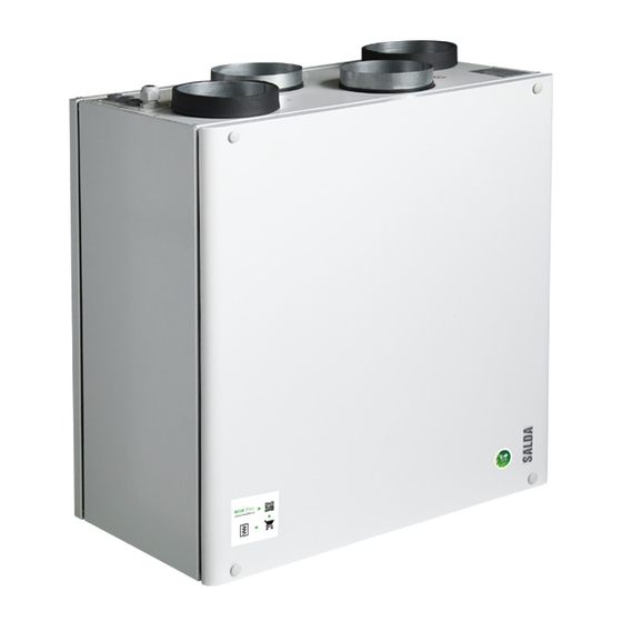
- Page 4 Key - 1 pcs. Smarty 2R VE is a residential air handling unit with a high efficiency (up to 75 %) rotor heat exchanger with integrated electrical heater. The unit pro- vides ventilation in the home and takes the heat from the exhausted air. AHU complies with ErP 2018 requirements. The unit is operated by a sepa- rate remote control panel or though separate MB-Gateway by PC.
- Page 5 Smarty 3X VEL Smarty 3X VEL Smarty 3X VER Smarty 3X VER Smarty 3X VEL 3.0 Smarty 3X VEL 3.0 Smarty 2R VE Smarty 3X VER 3.0 Smarty 3X VER 3.0 Smarty 3X VEL Smarty 3X VEL Smarty 3X VER Smarty 3X VER Smarty 3X VEL 3.0...
- Page 6 Smarty 2R VE Unplug unit from mains before opening the door (disconnect the power plug from the outlet or if there is a two-pole automatic circuit breaker installed – disconnect it as well. It is necessary to ensure that it won’t be turned on by third parties) and wait until the full stop of the fans (for about 2 min.).
- Page 7 Smarty 2R VE Be sure the unit is disconnected from power source before performing any maintenance or repair. • Electrical heater does not need to be serviced additionally. It is compulsory to change fi lters as described above. • Heaters have 2 thermal protections: automatically self-resetting, which activates at +50°C and the manually restored, which activates at +100°C.
- Page 8 Smarty 2R VE • Rotor heat exchanger must be serviced once a year. • Ensure that the gaps of the heat exchanger are clean, the brushes are not worn, the belt drive is not worn and the clamping nodes of the rotor heat exchanger are tight.
- Page 9 Smarty 2R VE 320 mm 598 mm 598 mm 598 mm 224,5 mm 273,1 mm 100,4 mm 286 mm Ø 175 mm Ø 125 mm 237,7 mm 276,3 mm 84 mm Installation should only be performed by qualified and trained staff.
- Page 10 Smarty 2R VE Mounting on the wall. a) To reduce the vibration stick the insulating tape on the unit‘s cas- ing side which touches the wall before mounting the unit on the wall. b) The unit has to be mounted on the mounting brackets.
- Page 11 Smarty 2R VE •Supply voltage to the unit must be connected by a qualified specialist following the manufacturer’s instructions and effective safety instructions. •The unit’s power network voltage must correspond to electrotechnical parameters of the unit indicated in the technical decal (~230V; 50 Hz).
- Page 12 Smarty 2R VE Performance Technical data Power consumption Supply air - phase/voltage [50 Hz/VAC] ~1/230 v [l/s] Heat exchange - power/current [kW/A] 0,006/0,1 v [l/s] P [W] -thermal efficiency up to P [W] Heater - power/current [kW/A] 0,6/2,61 - phase/voltage...
- Page 13 Smarty 2R VE Smarty 3X VEL Smarty 3X VER Smarty 3X VEL 3.0 Smarty 3X VER 3.0 Smarty 3X VEL Smarty 3X VER Smarty 3X VEL 3.0 Smarty 3X VER 3.0 Exhaust air Smarty 3X VEL Smarty 3X VER Smarty 3X VEL 3.0 Smarty 3X VER 3.0...
- Page 14 Smarty 2R VE S-RFF-U-D-F2 Stouch MB Gateway (F7/F7) (M5/M5) Modbus Gateway & web Panel filter Panel filter Humidity sensor (room) Remote control server MB Gateway GKOFIL0016 GKOFIL0015 ZAKKT0050 PRGPU51 GAUMBGATEWAY001 S-RCO2-F2 S-KCO2 S-KFF-U Cooker hood Cooker hood Front cover Cooker hood for stainless...
- Page 15 Smarty 2R VE Rotor belt Door Rotor motor Hall H1A-D12P24-1 Rotor box belt Rotor box motor Fan supply/exhaust Smarty 2R VE durys Hall sensor GNGO0062 ZVAR0133 GPUVRA009 GNGO0061 PJUT0006 MCB V1.0 TA/TL Rotor box Rotor box Extract/ Outdoor air tem-...
- Page 16 Smarty 2R VE Functions and logic of the control board are designed on the basis of DIN 1946-06 and EN 12098-3 standards. MCB control board can be controlled with: MB - GATEWAY web application Ptouch remote control panel Stouch remote control panel...
- Page 17 Smarty 2R VE Heat exchanger frost protection activated Anti-frost protections of the heat exchanger is activated Change filters Warning about dirty filters. Pressure relay or filter timer Room RH 3 days average is lower than 30%. Activated protection from dryness. Room RH 3 days average is lower than 30%. Limiting air flow.
- Page 18 Smarty 2R VE Date and time setting For the proper operation of schedule, events, and heating season functions it is necessary to set the date and time. Weekly schedule Weekly schedule consists of 10 weekly events. They can be added, deleted, activated and deactivated. Time, mode and day of the week are set for one event.
- Page 19 Smarty 2R VE of CO reduction is switched off. Air flow reduction by the temperature If the supply air temperature is more important than the air flow, it is possible to turn on air flow reduction depending on the temperature function. If all the heating power is consumed on the desired temperature support and the desired result is not reached, then reduction of the air flow starts in order to support enough power for required temperature maintenance.
- Page 20 Smarty 2R VE Electric heaters thermo protection Electric heater may have two protections. One is automatic, the other manual. Automatic protection automatically shuts down when the heater is cooled, manual protection must be turned off by pressing the switch which is on the heater.
- Page 21 Smarty 2R VE Alarm! Extract fan failure Alarm! DX cooler failure Alarm! Fire Alarm! Supply fan pressure protection. System stopped. Alarm! Extract fan pressure protection. System stopped. Alarm! Internal system error. Alarm! Heater manual protection. Boosting. Alarm! Preheater manual protection. Boosting.
- Page 22 Smarty 2R VE By pressing B1 indication L2, L3 and L7 are blinking, L4, L5, L6 are shining. Split screen shows “CO2”. blow off „CO2“is not shown tempo- By pressing B1 indication “CO2” is not shown for one minute, thus permitting to L2-L7 rary.
- Page 23 Smarty 2R VE A.10 Supply air temperature is too low. The system is off. A.11 Supply air temperature is too high. The system is off. A.12 Please change the supply air filter (pressure relay). The system is off. A.13 Please change the exhaust air filter (pressure relay). The system is off.
- Page 24 Smarty 2R VE Number Definition Number Definition Date and time. Menu button. Operating mode (comfort, max boost, stand-by, building pro- Click to set a desired room temperature. tection or economy). Click to choose the operating mode (comfort, max boost, Temperature of extracted air (room temperature).
- Page 25 Smarty 2R VE Number Definition Number Definition Current operating mode. STANDBY – AHU is stopped. BUILDING PROTECTION – maintain minimal air movement. Temperature can be maintained depending on settings in Menu → Set Points. ECONOMY – use decreased fan speed. Temperature can be maintained depending on settings in Menu →...
- Page 26 Smarty 2R VE Number Definition Number Definition Supplied air temperature. Current operating mode. Exhausted air temperature. Max boost function state. Extracted air temperature. Speed of the air supplying fan. Outside air temperature. Speed of the air extracting fan. Default Default Definition...
- Page 27 Smarty 2R VE Number Definition Number Definition Set date & time indication. Buttons to increase value. Year. Buttons to decrease value. Month. Day. Hour (24h format). Minute. Number Definition Number Definition Selected event (light color). Event scrolls (10 weekly events available).
- Page 28 Smarty 2R VE Number Definition Number Definition Selected event (light color). Event scrolls (10 weekly events available). New mode. The mode with a green strip will be set as current Select event. on occurrence of selected event. Active weekdays (green strips); inactive weekdays (gray Buttons to select mode.
- Page 29 Smarty 2R VE Number Definition Number Definition Set boost period. Button to increase value. Max period of boost (in seconds). Button to decrease value. Default Default Number Definition Number Definition [range] [range] Function state: green strip – on; gray – off.
- Page 30 Smarty 2R VE Number Definition Number Definition List of current active alarms. Previous list page. Next list page. Refresh list. www.salda.lt...
- Page 31 Smarty 2R VE www.salda.lt...
- Page 32 Smarty 2R VE www.salda.lt...
- Page 33 Smarty 2R VE www.salda.lt...
- Page 34 Smarty 2R VE www.salda.lt...
- Page 35 Smarty 2R VE www.salda.lt...
- Page 36 Smarty 2R VE www.salda.lt...
- Page 37 Smarty 2R VE www.salda.lt...
- Page 38 Smarty 2R VE www.salda.lt...
- Page 39 Smarty 2R VE www.salda.lt...
- Page 40 Smarty 2R VE www.salda.lt...
- Page 41 Smarty 2R VE www.salda.lt...
- Page 42 Smarty 2R VE 5 0 c m i n . min. 60 cm max. 400m Where the channel CO transmitter is used: it must be installed in the extract air duct. Tool for drilling holes are required for its installation.
- Page 43 Smarty 2R VE • Electrical connection can only be implemented by the qualified electrician in accordance with the applicable international and national electrical safety requirements and requirements for installation of electrical devices. • Use only power source which meets the requirements specified on the device label.
- Page 44 Smarty 2R VE 1 - LED1 indicator 2 - control panel name 3 - remote controller 4 - kitchen hood www.salda.lt...
- Page 45 Smarty 2R VE SL1 DIP switch Purpose (ON position) RS422_Z RS422_Y A+Y (RS422->RS485) RS422_A RS422_B B+Z (RS422->RS485) GND (signal) +24VDC GND (power) 120R line termination resistor 1kR connection line pull-up resistor 1kR connection line pull-down resistor RS485_A RS485_B +24VDC ModBus RTU...
- Page 46 Smarty 2R VE b. Modbus TCP/IP (connect with TCP/IP Modbus gateway (MB-GATEWAY)) Set IP of TCP/IP Modbus gateway (MB-GATEWAY) Press to connect 2. Connect to device (press “CONNECT” button) Device software version Configuration read status Configuration write status Press to disconnect from device...
- Page 47 Smarty 2R VE 3. Read configuration from device and save to your computer (press “READ CONFIG FROM BOARD” button and write configuration file name) 4. Write configuration to device from your computer (press “WRITE CONFIG TO BOARD” button and select configuration file)
- Page 48 Smarty 2R VE 1. All equipment manufactured in our factory is checked in operating conditions and tested befor delivery. Test protocol is supplied together with the unit. The equipment is shipped in good working order and condition to the direct client. The unit is warrantied for the period of two years from the invoice date.
- Page 49 Smarty 2R VE www.salda.lt...
- Page 50 Smarty 2R VE www.salda.lt...
Need help?
Do you have a question about the Smarty 2R VE and is the answer not in the manual?
Questions and answers