Salda AMBERAIR COMPACT RH Series Mounting And Installation Instruction
Source: salda.lt/en, vetter-lufttechnik.de
Table of Contents
Advertisement
Quick Links
Advertisement
Table of Contents

Subscribe to Our Youtube Channel
Related Manuals for Salda AMBERAIR COMPACT RH Series


Summary of Contents for Salda AMBERAIR COMPACT RH Series
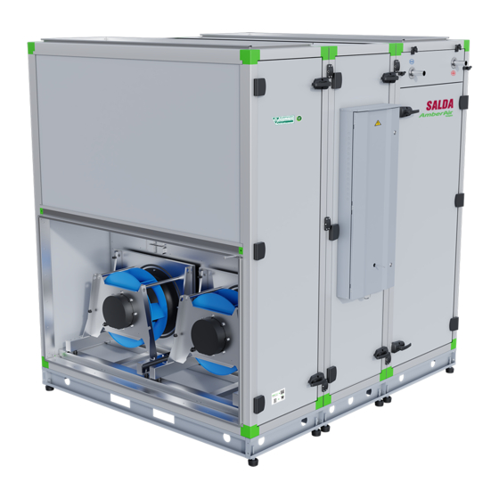
- Page 1 AMBERAIR COMPACT RH MOUNTING AND INSTALLATION INSTRUCTION...
-
Page 2: Table Of Contents
1. CONTENTS 2. SYMBOLS AND MARKING 3. SAFETY INSTRUCTIONS AND PRECAUTIONS 4. INFORMATION ABOUT THE PRODUCT 4.1. DESCRIPTION 4.1.1. CASING 4.2. DIMENSIONS AND WEIGHT 4.3. TECHNICAL DATA 4.4. OPERATING CONDITIONS 4.5. STANDARD PACKAGE OF COMPONENTS 4.6. DESCRIPTION OF COMPONENTS 4.7. SPARE PARTS 5. -
Page 3: Symbols And Marking
AmberAir Compact SD50+ units designed of the VDI 6022 Part 1 guideline (Hygiene require- ments for ventilation and air-conditioning systems and units) SALDA world like to inform you that based on the Commission Regulation (EU) No 1253/2014 for enforcing directive 2009/125/EC (hereinafter referred to as ErP diretive), the operational area of certain AHU within the European Union is regulated by certain conditions. -
Page 4: Information About The Product
Main safety rules Danger • Before performing any electrical or maintenance tasks make sure, that the device is disconnected from the mains, that all moving parts of the device have stopped. • Make sure that the fans can not be accessed through air ducts or branch openings. •... -
Page 5: Casing
4.1.1. CASING The casing of AmberAir Compact SD50+ unclear meaning and thermal characteristics. More detailed information is provided in the tables below. EN 1886:2008 data MODEL BOX MD50 SD50 MD50+ SD50+ Casing strength class D2(M) D1(M) D2(M) D1(M) Casing air leakage class at - 400 Pa L1(M) L1(M) L1(M) -
Page 6: Dimensions And Weight
Figure 4.1.1.3 - AmberAir MD50+ cross-section 1 – Corner profile with thermal break strips, 2 – intermediate profile with thermal break strips, 3 – special corner profile with thermal break strips for connection between two sections, 4 – double skin stone wool panel, 5 - rounded profile corners, 6 – non-porous gasket fitted in special groove, 7 –... -
Page 7: Technical Data
L2/L2* Dimensions, [mm] 2230 1905 2105 2180 1753 1753 Weight, [kg] 950* *Specified weight can vary depending on selected unit configuration 4.3. TECHNICAL DATA ELECTRICAL DATA Fans power, Fans curent, Fans phase/ Heat power, heater curent heater phase/ Total power and Model [kW] voltage, [?/V]... -
Page 8: Operating Conditions
METAL IMPELLER 7 RH F1 E1 5,00 3~ / 400 39,02 3~ / 400 32,5 / 50,02 7 RH F1 E2 5,00 3~ / 400 43,36 3~ / 400 35,5 / 54,36 7 RH F1 E3 5,00 3~ / 400 73,71 3~ / 400 56,5 / 84,71... -
Page 9: Standard Package Of Components
4.5. STANDARD PACKAGE OF COMPONENTS Standard package (without optional accessories) includes: Anti-vibration pad Set of bolts and nuts for Supply air temperature Seal profile pad connection sensor TJ 4.6. DESCRIPTION OF COMPONENTS outdoor air supply air extract air exhaust air 1 - supply air fan;... -
Page 10: Spare Parts
4.7. SPARE PARTS Durys 7RH-PVS/IVS 2058x553 -PU GPUD232_1162M Durys 7RH-PVS/IVS 2058x553-Vata GPUD232_1165M Durys 7RH-PVS 1838x758 -PU GPUD232_1177M Durys 7RH-PVS 1838x758-Vata GPUD232_1164M Door Durys 7RH-RS 2058x553 -PU GPUD232_1162M Durys 7RH-RS 2058x553-Vata GPUD232_1169M Durys 7RH-RS H2xW2 -PU-250 GPUD232_1175M Durys 7RH-RS H2xW2-Vata-250 GPUD232_1176M Vent. -
Page 11: Instalation
Variklis OJ-MRHX-3P04-15 Variklis OJ-MRHX-3P08-15 Rotor drives and controllers Valdiklis rot. OJ-DRHX-1220-MAD5 8Nm ZAKVA055 Valdiklis rot. OJ-DRHX-1220-MAD5 4Nm ZAKVA054 Šild. el. AAC 7R-27-3f-NIS-H ZESAAC027 Šild. el. AAC 7R-27-3f-NIS-V ZESAAC028 Šild. el. AAC 7R-30-3f-NIS-H ZESAAC025 Electrical heaters Šild. el. AAC 7R-30-3f-NIS-V ZESAAC026 Šild. -
Page 12: Unpacking
The product is heavy. Exercise caution when transporting and installing. W/W* Dimensions, [mm] 2480 2150 2350 1000 * - Extended rotor section pallet lenght The product can be lifted with a forklift or a crane using slings. When lifting with a forklift, the length of the fork must be greater than the length or width of the product (depending on the product version). Figure 5.2.1 - AmberAir Compact lifting with a forklift When lifting the product with slings, it is necessary to insert spacers between them in order to prevent damage to the casing of the product. -
Page 13: Mounting Diagram
• AmberAir Compact are lifted from the pallet with a forklift at the recesses at the supporting base, or with slings. 5.4. MOUNTING DIAGRAM Figure 5.4.1 - With automatic Figure 5.4.2 - Prie-wiring Figure 5.4.3 - GK AMBERAIR COMPACT RH v2019.08 EN |... -
Page 14: Mounting
Figure 5.4.4 - KPS Figure 5.4.6 - Ventilated premises Figure 5.4.5 - Indication for duct connection. ODA - outdoor air; SUP - supply air; ETA - extract air; EHA - exhaust air. LIST OF COMPONENTS Fire damper actuator I FILTER1 Supply air prefilter Fire damper actuator II FILTER2... -
Page 15: Place Requirements For The Equipment And Mounting Positions
The protective film is intended to protect the unit during transportation. It is recommended to remove the film because oxida- tion signs may occur. The products shall be installed on the legs. In order to do so, the unit should be slightly lifted. The hoisting methods are shown in the section “Transportation and Storage”. -
Page 16: Connection Of Air Ducts
Space for door opening L, [mm] 2000 outdoor air supply air extract air exhaust air H1-R H1-L H2-R H2-L HV1-R HV1-L HV2-R HV2-L HV3-R HV3-L HV4-R HV4-L HV5-R HV5-L HV6-R HV6-L 5.6. CONNECTION OF AIR DUCTS • Connected air ducts must be straight and have their own fixing. •... -
Page 17: Connection Of The Unit To Electric Network
• In order to reduce air loss in the system, the air ducts and profile parts should be of class C and higher. Their catalog can be found in our website. • If air handling unit is installed in heated premises, outdoor and exhaust air ducts must be insulated in order to avoid heat loses and condensing. If AHU is installed outdoors, it’s recommended to insulate all the air ducts. -
Page 18: Filters And Prefilter Maintenance
Make sure, that units’ switch is at off position (1 pic.). Turn the handles 90 degrees (2 pic.). After pulling the doors towards yourself, return the handles to the primary position (3 pic.). Open the doors (4 pic.). All the doors of AmberAir Compact units can be opened accordingly. If the AHU is equipped by electrical heater, then, in order to open the doors just unscrew all 4 holding handles (5-8 pic.), remove the screws from the inner side, after opening the side door (Fig. -
Page 19: Heat Exchanger Maintenance
• Do not plunge the motor into any fluid while cleaning impeller. • Make sure, that impeller’s balance weights are not moved. • Make sure the impeller is not hindered. • Mount the fan back into the unit. Connect the fan to power supply source. Connect air pressure hose. •... -
Page 20: Control Board Maintenance
6.6. CONTROL BOARD MAINTENANCE • Before starting maintenance or repair work, make sure that the unit is disconnected from the electrical net work and main switch is turned off. • Turn off the main switch of the product. • Open the doors of the product. •... -
Page 21: Control
Ventilation unit can be controlled using a remote control, web interface via MB-Gateway and building management system. More information about the possibilities of controlling is provided in the table below. MB-Gateway + WIFI + SALDA AIR app Stouch FLEX MCB... - Page 22 Air dampers Outdoor air damper control Fans 0-10V control Supply/exhaust air fan fail indication (NC) Protection by RPM Air flow protection by pressure Sensors Supply air temperature sonsor Outdoor air temperature sensor DTJ extract air temperature and humidity sensor Exhaust air temperature sensor After rotor air temperature sensor Water heater temperature sensor Water cooler temperature sensor...
-
Page 23: Description Of The Units Functions
The following control board functions can be fully con trolled only with SA-Control remote con trol panel, MB-Gateway web application or SALDA AIR app. In case of Stouch remote con trol panel use the description of remote control panel functions for MCB control board. - Page 24 FREHI LRWC LREHI LSVS ELECTRICAL ACCESSORIES detector (room) S-RCO2-F2 ZAKKT0048 detector (duct) S-KCO2 ZAKKT0049 Humidity detector (duct) S-KFF-U ZAKKT0051 Humidity detector (room) S-KFF-U-D-F2 ZAKKT0050 Wireless N Nano Router TP-Link TL-WR802N PRGPU105 Remote control panel SA-Control PRGPU126 remote (with logo) S-Touch PRGPU051 Network module MB-Gateway...
- Page 25 LJ/E 174,7x51,6 GLJLJ/E052 Flexible connection LJ/E 174,7x96,7 GLJLJ/E051 STP-C 1747x516-710 GSFSTPR161_1000 Reducer STP-C 1747x967-710 GSFSTPR161_1001 Silencer AKS 710- 800-10 GSOAKS126 Flexible connection LSVF 710 GVELSVF018 Outlet-intake cover ABV 710 GFDABV0710 Damper SKG 710-M GSKSKG065 Mixing point Valve VVP/VXP Electrical heater mounting legs (for bottom chanel) LREHI 1755x973 78-126 GNGPR168_1321M 78-126 kW...
-
Page 26: Connection Fo Accessories
CB 1747x967-R CW2+DE GSIASD0082 CB 1747x967-R CW4+DE GSIASD0083 CB 1747x967-R CDX2+DE GSIASD0084 CB 1747x967-R CDX4+DE GSIASD0085 CB 1747x967-R HW1+CW2+DE GSIASD0086 CB 1747x967-R HW1+CW4+DE GSIASD0087 CB 1747x967-R HW1+CDX2+DE GSIASD0088 CB 1747x967-R HW1+CDX4+DE GSIASD0089 CB 1747x967-R HW2+CW2+DE GSIASD0090 CB 1747x967-R HW2+CW4+DE GSIASD0091 CB 1747x967-R HW2+CDX2+DE GSIASD0092 CB 1747x967-R HW2+CDX4+DE... - Page 27 Fire alarm damper actuator I (supply air) Water heater temperature sensor Fire alarm damper actuator I (exhaust air) Water heater circulation pump Fire alarm damper I open Water cooler temperature sensor Fire alarm damper I closed Water cooler control output 0-10VDC Fire alarm damper II open Water cooler circulation pump Fire alarm damper II closed...
- Page 28 SAF Fan Q3 - L1 SAF Fan Q3 - L2 SAF Fan Q3 - L3 EAF Fan Q4 - L1 EAF Fan Q4 - L2 EAF Fan Q4 - L3 Black Heater Q5 - L1 Brown Heater Q5 - L2 Gray Heater Q5 - L3 Blue...
- Page 29 SAF Fan Q3 - L1 237-1 SAF Fan Q3 - L2 237-1 SAF Fan Q3 - L3 237-1 EAF Fan Q4 - L1 238-1 EAF Fan Q4 - L2 238-1 EAF Fan Q4 - L3 238-1 Black Heater Q5 - L1 225-2 Brown Heater Q5 - L2...
- Page 30 SAF Fan Q3 - L1 04-1 SAF Fan Q3 - L2 04-1 SAF Fan Q3 - L3 04-1 EAF Fan Q4 - L1 05-1 EAF Fan Q4 - L2 05-1 EAF Fan Q4 - L3 05-1 Black Heater Q5 - L1 06-2 Brown Heater Q5 - L2...
- Page 31 -PS1.1 -PS1.2 -PS2 RL_NC RL_C RL_NO 0-10V K1 (A2) K1 (A1) 0-10V Figure 8.1.4.4 - 7-E3-C2 AMBERAIR COMPACT RH v2019.08 EN |...
- Page 32 W18\brown W18\white W19\brown W19\white W17\black W17\brown W17\grey W17\gr/ye White White White White White White Figure 8.1.4.5 - 7-IVS-F1,F2,F3 | EN AMBERAIR COMPACT RH v2019.08...
- Page 33 W10\brown W10\white W11\brown W11\white W13\Shield W13\gr/ye W13\black W13\brown W13\grey W12\Shield W12\gr/ye W12\black W12\brown W12\grey White White White White White White White White White White White Figure 8.1.4.6 - 7-IVS-F4 AMBERAIR COMPACT RH v2019.08 EN |...
- Page 34 -PS1 White X102 : 3 3-NC 1-COM 2-NO White X102 : 4 Figure 8.1.4.7 - 7-IVS-PS 1X | EN AMBERAIR COMPACT RH v2019.08...
- Page 35 -PS1.1 White X102 : 1 3-NC 1-COM 2-NO White X102 : 2 -PS1.2 White X102 : 3 3-NC 1-COM 2-NO White X102 : 4 Figure 8.1.4.8 - 7-IVS-PS 2X AMBERAIR COMPACT RH v2019.08 EN |...
- Page 36 W16\gr/ye W16\Shield W16\black W16\brown W16\grey W16\gr/ye White White White White White White W15\white W15\brown W14\green W14\yellow W14\red W14\red W14\yellow W14\white W14\white Figure 8.1.4.9 - 7-PVS-F1,F2,F3 | EN AMBERAIR COMPACT RH v2019.08...
- Page 37 W9\white W9\brown W8\green W8\yellow W8\red W8\red W8\yellow W8\white W8\white W6\Shield W6\gr/ye W6\black W6\brown W6\grey W7\Shield W7\gr/ye W7\black W6\black W7\black W7\brown W6\brown W7\brown W7\grey W6\grey W7\grey W6\gr/ye W7\gr/ye White White White White White White White White White White White Figure 8.1.4.10 - 7-PVS-F4 AMBERAIR COMPACT RH v2019.08 EN |...
- Page 38 Green-yellow Black Brown Gray 0.75 Blue 0.75 Brown White White White White White White Green-yellow Black Brown Gray Green-yellow Black Brown Gray Green-yellow Black Brown Gray Figure 8.1.4.11 - 7-PVS-KE | EN AMBERAIR COMPACT RH v2019.08...
- Page 39 -PS2 White X103 : 1 3-NC 1-COM 2-NO White X103 : 2 Figure 8.1.4.12 - 7-PVS-PS 1X AMBERAIR COMPACT RH v2019.08 EN |...
- Page 40 White X103 : 9 1_COM 2_NO White X103 : 10 4_NC Figure 8.1.4.13 - 7-PVS-T1 | EN AMBERAIR COMPACT RH v2019.08...
- Page 41 Green-yellow Black Brown Gray 0.75 Blue 0.75 Brown White White White White White White Green-yellow Black Brown Gray Green-yellow Black Brown Gray Green-yellow Black Brown Gray Figure 8.1.4.14 - 7-RS-E1/E2/E3 AMBERAIR COMPACT RH v2019.08 EN |...
- Page 42 W3\black W3\brown W3\grey W3\gr/ye Green-yellow White White White White White White White White White White White White White White White White White White Figure 8.1.4.15 - 7-RS-W | EN AMBERAIR COMPACT RH v2019.08...
- Page 43 -Power Green-yellow W20\gr/ye Black W20\black Brown W20\brown L3/N Gray W20\grey 10VDC W20\Shield -Control 24VDC White White White White White White Figure 8.1.4.16 - 7-VM AMBERAIR COMPACT RH v2019.08 EN |...
- Page 44 Black Black 02-1 Brown Brown 02-1 Gray Gray 02-1 Blue Blue Brown Brown Green-yellow 02-4 Green-yellow Green-yellow 02-1 Brown Blue Green-yellow Green-yellow 02-1 Blue Brown Green-yellow Green-yellow 02-4 Brown Blue Green-yellow Green-yellow 02-4 0.75 Green-yellow 0.75 Green-yellow 0.75 Green-yellow 0.75 Blue 0.75 Brown...
- Page 45 PS1.1 PS1.2 RL_NC RL_C RL_NO 0-10V Water heater temperature sensor Figure 8.1.4.18 - 7-W-C2 AMBERAIR COMPACT RH v2019.08 EN |...
- Page 46 Fresh air temperature sensor Supply air temperature sensor Extraxt air humidity and temperature sensor Exhaust air temperature sensor Afte rotor air temperature sensor Figure 8.1.4.19 - | EN AMBERAIR COMPACT RH v2019.08...
- Page 47 -J10 -J12 -J11 -J13 -J15 Figure 8.1.4.20 - IVS-MODBUS 1X AMBERAIR COMPACT RH v2019.08 EN |...
- Page 48 -J10 -J12 -J11 -J13 -J15 -J14 -J17 -J19 Figure 8.1.4.21 - IVS-MODBUS 2X | EN AMBERAIR COMPACT RH v2019.08...
- Page 49 794715-1 OJ-DRHX Figure 8.1.4.22 - RSD Book # DUTIES / NAME SIGNATURE DATE SALDA UAB 2018-06-14 DRAWN BY Drawing # 2018-06-14 CHECKED BY Principal connection scheme APPROVED BY Revision: AMBERAIR COMPACT RH v2019.08 EN |...
- Page 50 -EK4 -EK5 3, 4 Black Black -EK6 Black Black Black Black -EK7 Black Black -EK8 12, 13 Black Black Black Black -EK9 19 19 Black -EK7 Black Black Black -EK8 23, 24 Black Black -EK9 30, 31 Black Black 35, 36 Black Black Black...
- Page 51 - L1 - L2 - L3 - PE Black Black X9 CONTROL1 -EK1 Black Black X7 HEAT1 -EK2 Black Black -EK3 Black Black Black Black Black -EK4 Black Black -EK5 Black Black Black Black -EK6 -EK7 Black Black -EK8 Black Black Black Black...
- Page 52 -EK4 Black Black -EK5 3, 4 Black Black Black Black -EK6 30, 31 Black Black 35, 36 Black Black Black X9 CONTROL1 -EK1 38, 39 Black X7 HEAT1 -EK2 40, 41 Black Black -EK3 Black 34, 43 44 44 Blue Black DI AT Black...
- Page 53 -EK4 Black Black -EK5 Black Black 3, 4 Black Black -EK6 30, 31 Black Black 35, 36 Black Black Black X9 CONTROL1 -EK1 38, 39 Black X7 HEAT1 -EK2 40, 41 Black Black -EK3 34, 43 Black 44 44 Blue Black DI AT Black...
- Page 54 - L1 - L2 - L3 - PE Black Black X9 CONTROL1 -EK1 Black Black X7 HEAT1 -EK2 Black Black -EK3 Black Black Black Black Black -EK4 Black Black -EK5 Black Black Black Black -EK6 -EK7 Black Black -EK8 Black Black Black Black...
- Page 55 Black Black X9 CONTROL1 -EK1 14, 15 Black Black X7 HEAT1 -EK2 Black Black -EK3 Black Black Black Black Black -EK4 Black Black -EK5 Black Black 31, 32 Black Black -EK6 -EK7 Black Black Black - L1 -EK8 Black Black Black 39, 40 - L2...
- Page 56 Black Black X9 CONTROL1 -EK1 Black Black 14, 15 X7 HEAT1 -EK2 Black Black -EK3 Black Black Black Black Black -EK4 Black Black Black - L1 -EK5 Black Black Black 28, 29 - L2 Black Black Black - L3 -EK6 - PE -EK7 Black...
- Page 57 L -supply X32:1 - DO1 X32:2 - N(L1) X32:3 - PE X32:4 - DO2 L -supply X32:5 - N(L1) X32:6 - PE X23:1 - DI9 X23:2 - +12VDC X23:3 - DI10 X23:4 - +12VDC X35:1 - PE X35:2 - N(L1) X35:3 - DO5 L-supply X35:4 - DO6...
- Page 58 1-G0 X3:1:AO4 X3:2:GND X3:3:AO5 X3:4:GND X3:5:AO6 X3:6:GND X4:1:AI1 X4:2:GND X4:3:AI2 X4:4:GND X4:5:AI3 X4:6:GND X11:1:DO5-NC X11:2:DO5-NO X11:3:DO5-COM X11:4:DO4-NC X11:5:DO4-NO X11:6:DO4-COM X14:1:DI5-12VDC IN/GND X14:2:DI5-12VDC OUT/TACHO IN X14:3:DI6-12VDC IN/GND 1-COM 3-NC 2-NO X14:4:DI6-12VDC OUT/TACHO IN X14:5:DI7-12VDC IN/GND X14:6:DI7-12VDC OUT/TACHO IN X14:7:DI8-12VDC IN/GND X14:8:DI8-12VDC OUT/TACHO IN X10:1:DO7-NC X10:2:DO7-NO X10:3:DO7-COM...
- Page 59 TV3_P/TV3_I X1:1:DI2 X1:2:+12VDC X1:3:DI1 X1:4:+12VDC X1:5:DI4 X1:6:+12VDC X1:7:DI3 X1:8:+12VDC X2:1:AO1 X2:2:GND X2:3:AO2 X2:4:GND X2:5:AO3 Water cooler 0-10V X2:6:GND control X4:1:AI1 X4:2:GND X4:3:AI2 Water cooler ret. fluid X4:4:GND temperature sensor X4:5:AI3 X4:6:GND X12:1:DO3-NC X12:2:DO3-NO Water cooler power line X12:3:DO3-COM X12:4:DO2-NC X12:5:DO2-NO X12:6:DO2-COM X8:1:+24VDC/24VAC(L) X8:2:GND/24VAC(N)
- Page 60 X4:1 - DI4 X4:2 - +12VDC X22:7 - DI8 X22:8 - +12VDC X27:1 - IND_1 X27:2 - +24VDC X27:3 - IND_2 X27:4 - +24VDC System mode switch X21:5 - DI3 X21:6 - +12VDC Fan speed switch X21:7 - DI4 X21:8 - +12VDC Figure 8.1.4.33 - SP DI/DO | EN AMBERAIR COMPACT RH v2019.08...
- Page 61 X1:1:DI2 Electrical heater X1:2:+12VDC manual protection (NC) 0-10V X1:3:DI1 Electrical heater X1:4:+12VDC automatic protection (NC) X1:5:DI4 X1:6:+12VDC X1:7:DI3 X1:8:+12VDC X2:1:AO1 Electrical heater X2:2:GND 0-10V control X2:3:AO2 X2:4:GND X2:5:AO3 X2:6:GND X13:1:DO1-NC X13:2:DO1-NO Electrical heater X13:3:DO1-COM power line X13:4:DO8-NC X13:5:DO8-NO X13:6:DO8-COM Figure 8.1.4.34 - SP-HE AMBERAIR COMPACT RH v2019.08 EN |...
- Page 62 TV2_P/TV2_I X1:1:DI2 X1:2:+12VDC X1:3:DI1 X1:4:+12VDC X1:5:DI4 Water heater protection X1:6:+12VDC (thermostat) (NC) X1:7:DI3 Water heater circulation X1:8:+12VDC pump fail (NC) X2:1:AO1 X2:2:GND X2:3:AO2 Water heater X2:4:GND 0-10V control X2:5:AO3 X2:6:GND X4:1:AI1 Water heater ret. fluid X4:2:GND temperature sensor X4:3:AI2 X4:4:GND X4:5:AI3 X4:6:GND X12:1:DO3-NC...
- Page 63 X3:3 - DI2 Water heater protection X3:4 - +12VDC (thermostat) (NC) X6:5 - AI7(NTC) Water heater ret. fluid X6:6 - GND temperature sensor X39:1 - PE X39:2 - N(L1) Water heater power line X39:3 - DO8 X12:1 - PE 24VDC Power supply X12:2 - GND for water heater actuator X12:3 - +24VDC...
- Page 64 X21:1 - DI1 Electrical preheater X21:2 - +12VDC automatic protection (NC) X21:3 - DI2 Electrical preheater X21:4 - +12VDC manual protection (NC) X24:1 - GND 0-10V Outdoor air preheater X24:2 - AO1(0-10VDC) control output (0 10VDC) X42:1 - DO11 X42:2 - N(L1) Outdoor air preheater power line control Figure 8.1.4.37 -SP-PE...
- Page 65 PS1.1 PS1.2 RL_NC RL_C RL_NO 0-10V AMBERAIR COMPACT RH v2019.08 EN |...
-
Page 66: General Recommendations For The Maintenance Of Ventilation System
24VDC 24VDC 24VDC 24VDC Fresh air temperature sensor Supply air temperature sensor Extraxt air humidity and temperature sensor Exhaust air temperature sensor Afte rotor air temperature sensor Figure 8.1.4.38 7-N-C2 *The jumpers are installed by the manufacturer (see on the automatics switchboard). *All the external electrical connections must be made in accordance with effective legal acts and safety requirements. -
Page 67: Possible Faults And Troubleshooting
COMPONENT DURING START-UP AT LEAST EVERY 6 MONTHS Replace filters every 3 to 4 months or according to the console indications. Filters Check the cleanliness of the filters Make sure that the pressure relay/transmitter is clean and clean it if necessary. Check for any damaged filer fastening parts. -
Page 68: Declaration Of Confomity
Should any alterations be made in the products, this declaration will no longer apply. Notified body: VšĮ Technikos priežiūros tarnyba, Naugarduko g. 41, LT – 03227 Vilnius, Lithuania, identification number 1399. Quality: Salda UAB activities are in line with the international quality management system standard ISO 9001:2015. Date... -
Page 69: Warranty
3.4. when the unit was used not for its original purpose. 3.5. Company SALDA UAB is not responsible for potential loss of property or personal injury in cases where AHU is manufactured without a control system and the control system will be installed by the client or third parties. The manufacturer’s warranty does not cover devices that will be damaged by installing the control system. - Page 70 AMBERAIR COMPACT RH v2019.08...
- Page 71 AMBERAIR COMPACT RH v2019.08...
- Page 72 Every 3-4 Filter replacement months** * - Look at the product label. ** - At least. NOTE. The purchaser is required to fill in the “Product maintenance table”. MAN000198 MAN000198 Ragainės g. 100 +370 41 540 415 Šiauliai LT-78109, LITHUANIA office@salda.lt...
Need help?
Do you have a question about the AMBERAIR COMPACT RH Series and is the answer not in the manual?
Questions and answers