Salda Smarty 3X VER User And Service Manual
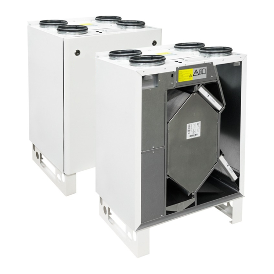
Ahu with heat recovery
Source: salda.lt/en, vetter-lufttechnik.de

Related Manuals for Salda Smarty 3X VER


Summary of Contents for Salda Smarty 3X VER
- Page 1 AHU WITH HEAT RECOVERY Smarty 3X VER Smarty 3X VEL Smarty 3X VER 3.0 Smarty 3X VEL 3.0 User‘s and service technical manual Subject to technical modification...
- Page 2 15. Boost/fireplace function 16. Bypass damper and its control Connection of the unit to electric network Recommendations for installation of functional modules (opera- tional, control measurement) CO2 concentration according to Pettenkofer limit Connection of the unit’s external functional modules www.salda.lt...
- Page 3 0.005 kW; 0.021 A; 24/50 V/Hz; ~- 0.17 kW; 1.87 A; IP-34 TOTAL: www.salda.lt gu072489 / 2014.03 Stick the auxiliary label on the unit (on an easily accessible place) or on the dashed place of a technical manual in order to keep the important information about the unit.
- Page 4 Extract – panel M5 (WxHxD) 435 x 175 x 25 mm Supply – panel F7 (WxHxD) 435 x 175 x 25 mm • Outdoor exploitation temperature +5 °C to +40 °C. Not suitable for swimming pools, saunas and other similar facilities. www.salda.lt...
- Page 5 • Unit is designed to supply/extract only clean air (free of chemical compounds causing metal corrosion, of substances aggressive to zinc, plastic and rubber, and of particles of solid, adhesive and fi bred materials). - temperature min./max. [°C] -15 / +40 - temperature min./max. [°C] +15 / +40 Supply Extract - humidity - max. humidity *With additional pre-heater www.salda.lt...
- Page 6 (when pressure switches are connected). When there is a folt in fans’ motor, any separate notice is shown on the control panel. Be sure the unit is disconnected from power source before performing any maintenance or repair. Smarty 3X VER, Smarty 3X VER 3.0 www.salda.lt...
- Page 7 Smarty 3X VE / Smarty 3X VE 3.0 Smarty 3X VEL, Smarty 3X VEL 3.0 www.salda.lt...
- Page 8 • Firstly take out heat exchanger cassette carefully. Submerge it into a bath and wash with warm soapy water (do not use soda). Then rinse it with weak hot water stream (too strong stream can fold the plates). Place back the heat exchanger only when it is completely dry. Smarty 3X VER, Smarty 3X VER 3.0 Smarty 3X VEL, Smarty 3X VEL 3.0 1.
- Page 9 [mm] Filter model Subject to technical modification Smarty 3X VEL Smarty 3X VER Smarty 3X VEL 3.0 Smarty 3X VER 3.0 Smarty 3X VEL Smarty 3X VEL Smarty 3X VER Smarty 3X VER Smarty 3X VEL 3.0 Smarty 3X VEL 3.0 Smarty 3X VER 3.0...
- Page 10 Smarty 3X VE / Smarty 3X VE 3.0 Smarty 3X VEL Smarty 3X VEL 3.0 ∅ 160 Smarty 3X VER Smarty 3X VER 3.0 ∅ 160 www.salda.lt...
- Page 11 • When using DX cooler we recommend to use the differential pressure rely for cooler protection (PS600). • Device power cable (CEE7 / 7) with a plug must be installed in a visible and accessible place for easy disconnection from its socket. Pic. 01 400mm Pic. 02 www.salda.lt...
- Page 12 Draining system must be installed in the premise where the tem- perature is not lower than 1°C. If temperature falls below 0°C the draining system should be isolated with thermal isolation. The Siphon (2) not necessarily must be mounted below the AHU (1), but below the 1st AHU level. www.salda.lt...
- Page 13 Supply air temperature sensor from automatics. CEE7/7 Power cable with plug DX cooler. There is only control signal from to unit’s automatics. RS485_2 BMS network connection place DX cooler‘s safety differential pressure relay RS485_1 Control panel connection place (PS600) www.salda.lt...
- Page 14 EKA NIS 160 1.0-1f Panel filter set Electric preheater Shut-off damper Actuator for damper Spring return actuator for GKOFILSMARTY3 PSIEKANIS03 GSKSKG003 ZAKP0027 damper ZAKP0063 FLEX Stouch EKA 160 0.3-1f Remote control panel Remote control panel Electric heater PRGPU015 PRGPU051 PSIEKA075 www.salda.lt...
-
Page 15: Other Information
30 – neutral (N) 34 – supply phase (L1) 31 – supply phase (L1) 35 – control (COM) 32 – protective earth (PE) 36 – control (0-10VDC) 33 – neutral (N) Maximum permissible connection power is 1kW (230V 50Hz) www.salda.lt... -
Page 16: Operation
• “OutDoor T.C” – selecting summer/winter temperature, 10-30°C. Default value: 16°C Time to cool heating elements upon switching off the unit may be configured by Flex remote control (default value – 60 seconds): Menu > additional >Add.Func.> FanStopTime (factory settings). www.salda.lt... - Page 17 X16), its control (configuration) is not possible. Standard speed configurations: • Building protection – 31%, motor operating voltage 2 V±5%, • Minimal – 45%, motor operating voltage 3,1V±5%, • Nominal – 74%, motor operating voltage 5,1V±5%, • Boost/židinys – 100%, motor operating voltage 10V. www.salda.lt...
- Page 18 6 and 7 of the Stouch remote control. 6 - GND (ground); 7 – 0–10VDC signal. Power to the sensor is supplied from a separate power supply source. Converter has separate power source. The installer has to assure power supply protection. www.salda.lt...
- Page 19 B4 B5 B6 L2 flashes. The segment display shows Intense ventilation the remaining time in seconds (time function(boost) switch- Hold B5 for 2 seconds. above 600 s is shown in minutes). Time is on/switch-off adjusted by touching B4 and B6. www.salda.lt...
- Page 20 Presssure transmitters are used only when connected by Flex remote control. The use of forced ventilation (“boost”) by a digital input. To activate this function a button or motion sensor (PIR) can be used. 4;5 – connection of an external button or PIR sensor www.salda.lt...
- Page 21 Connection of a functional node to a ventilation unit: 9 – Positive potential (+24VDC) “AHU Stop” 10 – Negative potential (-24VDC) “AHU Stop” 11 - Positive potential (+24VDC) “AHU Work” 12 - Negative potential (-24VDC) “AHU Work” Maximum power of one light indication cannot exceed 1.2W www.salda.lt...
- Page 22 If supply voltage is lost and reappears, the unit is operating according to the last settings. The risk of fire is recorded in 5 seconds after the signal is cut (when NO (Normally Open)). Connection of a functional node to a ventilation unit: To use this function, the short circuiter must be removed from terminals 13 and 14. It is normally installed by the manufacturer. www.salda.lt...
- Page 23 • “day T” – {15-40}°C maximum outdoor temperature • “Night T” – {0-15}°C minimum outdoor temperature • “Room T” – {10-30}°C room temperature • “Exercise” – {0-5} h. Purging and measuring take place regularly. If the setting is “0”, outdoor sensor must be routed outdoors. www.salda.lt...
- Page 24 When the time indicated by “STouch” remote control is over, the accident is shown “A.03”. When accident A.03 is cancelled, the filter timer is also automatically reset. Where STouch remote control is used, all settings made by Flex remote control are no longer used. Filter timer is recorded in the Stouch remote control. www.salda.lt...
- Page 25 • The power cable can be replaced only by a qualified specialist upon the evaluation of the rated power and current. The manufacturer does not assume any liability for personal injuries and property damage due to non-conformance with the provided instructions. www.salda.lt...
- Page 26 Where the supply air heater is used, the supply air sensor (SS) must be installed downstream of the heater (or cooler), if the sensor cable long enough, or to the first branching, turn of the air transportation system. Prior to connecting the unit to the power network, the door must be closed. Forced pressing of the door switch by side tools is prohibited. www.salda.lt...
- Page 27 If external units are connected to X16, they must be also disconnected prior to extending automation. Upon the full dismantling of the unit control automation and its re-installation, make sure that the connector conductors are not damaged or otherwise broken prior to connecting automation connectors. www.salda.lt...
- Page 28 Effect on an individual 3000 2500 Reduced concentration, drowsi- ness, headache, etc. 2000 1500 Pettenkofer limit Disturbs 1000 Pettenkofer limit Pleasant Šviežias lauko oras Duration of the presence in the room in hours www.salda.lt...
- Page 29 (FLEX) (see FLEX panel description II.6.6 for details on selecting this feature). There is boost time setting in minutes (factory setting: Off) in the user menu item Add.Func. For example, if 5min is set, then in case the signal is lost www.salda.lt...
- Page 30 • Switch on the mains voltage, switch on the blade switch Q, see Fig. 5 (actual appearance of the blade switch can be different from the given photo based on the model of the product). • Select the desired fan rotation speed and the supply air temperature using the remote controller. www.salda.lt...
- Page 31 (TJK-10K) controller PRV_V2.3 exhaust air damper actuator (TJK-10K) F1, F2, DTJ100.1 temp. and humidity sensor for extract air. fuse supply air fan EC R1, R2 relay extract air fan EC fire alarm input units door micro switch www.salda.lt...
- Page 32 Smarty 3X VE / Smarty 3X VE 3.0 www.salda.lt...
- Page 33 Smarty 3X VE / Smarty 3X VE 3.0 www.salda.lt...
- Page 34 Smarty 3X VE / Smarty 3X VE 3.0 www.salda.lt...
- Page 35 Smarty 3X VE / Smarty 3X VE 3.0 www.salda.lt...
- Page 36 The resistance between the fi fi rst and the last unit should be 120...150 Ω. The remote control can be connected to and disconnected from the unit only after switching off the supply voltage of the unit. Resistance Ω Switch 1 Switch 2 Microswitches 1 and 2 www.salda.lt...
- Page 37 Possible heater or unit failure. MUST address or malfunctioning (if installed) Manual protection is activated the servicing staff for failure detection and its elimination. Too low air flow at rated fan speed Clogged supply and/or extract air filter(s) Filter replacement needed www.salda.lt...
- Page 38 EC_0_100 EC- control of the EC motors using 0–10 V signal AC- control of the AC motors using three fixed voltages 11. „PSI.“ - when pressure support is selected, min. and max. limits are set for the pressure converter www.salda.lt...
- Page 39 „On“ – the controller works with UNI, PRO, TPC and FLEX remote controllers but doesn‘t support extended ModBus address list. „Off“ – controller works with FLEX remote controller and supports extended ModBus address list. 18.2. „empty1“ - unused 18.3.„empty2“ - unused 18.4. „empty3“ - unused 18.5.„empty4“ - unused www.salda.lt...
- Page 40 3. On the panel, in the menu Sensor overview, you can see instantaneous supply and exhaust air pressure values. 4. In case of any fault of the pressure converter, menu Emergency overview shows message GP sensor. Check if pressure converters are properly connected (only current input). www.salda.lt...
- Page 41 X16-2, X16-3 Deactivated by remote control LED5 (uždaroma) Heating X16-30, X16-31 Supply air electrical heater. Relay K6 LED13 LED6 (atidaroma) Rot.-Bypass Damper opened, heat exchanger closed. LED7 (uždaroma) Fan Run (System X16-11 ir X16-12. FanFail (System X16-9, X16-10 Alarm) www.salda.lt...
- Page 42 Max Supply OutDoor T.C. Cool. Ctrl. Min Supply ºС DX_CoolOn 23 % DX_CoolOff 20 % OutDoor T.C. ºС Add. Func. Night Cool. Fast Butt. standby FanStopTime Boost Ctrl. Boost timer 0 min Boost SAF 130 % Boost EAF 130 % www.salda.lt...
- Page 43 Exit Outdor air temp. Summer Winter 11MM RoomPI HeatPI ChilPI PreHeatPI NightCtrl Day T ºС Night T ºС Room T ºС Exercise Wheat W_crit ºС W_stop ºС Pump_stop 10 min Exercise 10 h Heater E_On/OFF Exch B_DMP VentUnit RHEC www.salda.lt...
- Page 44 PassiveTC Exercise AF 1 OutDoorTemp RotorPWM DefrStpTime PassiveTemp CONF1 3dayRH mean 3dayRHCurr 3dayOUTCurr St/Sp time CONF2 DIBTmenu Filters SetTimer 2160 h ReSetTimer reset Curr. Timer V2.4 programe coefficients Program SMARTY 3XVE-V2.4-0k Extra Modbus MBAddress Parity None Baudrate 4800 Stop www.salda.lt...
- Page 45 NightCtrl Day T Night T Room T Exercise Wheat W_crit W_stop Pump_stop 10 min Exercise 10 h Heater E_0_10 Exch B_DMP VentUnit RHEC FanType min_0V 0 Pa max_10V 330 Pa min_0V 0 ppm max_10V 1000 ppm PPM_100% 100 ppm www.salda.lt...
- Page 46 RotorPWM DefrStpTime PassiveTemp 3dayRH mean CONF1 3dayRHCurr 3dayOUTCurr St/Sp time CONF2 DIBTmenu Filters SetTimer 2160 h ReSetTimer reset Curr. Timer SAF Low SAF Normal SAF High 100% Preparing MAIN START Inicialization DATA Time To Messure GET ALL VALUES CONTROL www.salda.lt...
- Page 47 50 < Main PID < 100 Cooling Bypass Control Heating Toutside < Troom Toutside < Troom ByPass-OPEN Cold reccuperation Heat reccuperation ByPass-OPEN Toutside < -3 Texhaust<ExhaustSet PreHeater-Off PID Texhaust; ExhaustTest Ventilation with Temperature maintenance by controling ByPass Trying to maintenance Ex- haustTset www.salda.lt...
- Page 48 Smarty 3X VE / Smarty 3X VE 3.0 www.salda.lt...
- Page 49 11 ALARM Indicates when fans fail ON/OFF 24V 0.05mA Indicates when fans running ON/OFF 12 ANTI.F 0.05mA 15 A.0.10 Bypass 16 COM 17 +24V 24VDC 0.1A 18 COM 21 T.OUT Outdoor sensor TL Fresh (ambient) air temperature sensor. 22 COM www.salda.lt...
- Page 50 The blade switch should be disconnected during service (if installed on the device). If blade switch is not installed, disconnect the power supply from the distribution panel. www.salda.lt...
- Page 51 Smarty 3X VE / Smarty 3X VE 3.0 www.salda.lt...
- Page 52 Smarty 3X VE / Smarty 3X VE 3.0 www.salda.lt...
Need help?
Do you have a question about the Smarty 3X VER and is the answer not in the manual?
Questions and answers