Salda AKU Operation, Installation & Maintenance Instructions
Source: salda.lt/en, vetter-lufttechnik.de
Hide thumbs
Also See for AKU:
- Mounting and installation instruction (13 pages) ,
- Installation instruction (12 pages) ,
- Operation, installation & maintenance instructions (52 pages)

Subscribe to Our Youtube Channel
Related Manuals for Salda AKU


Summary of Contents for Salda AKU
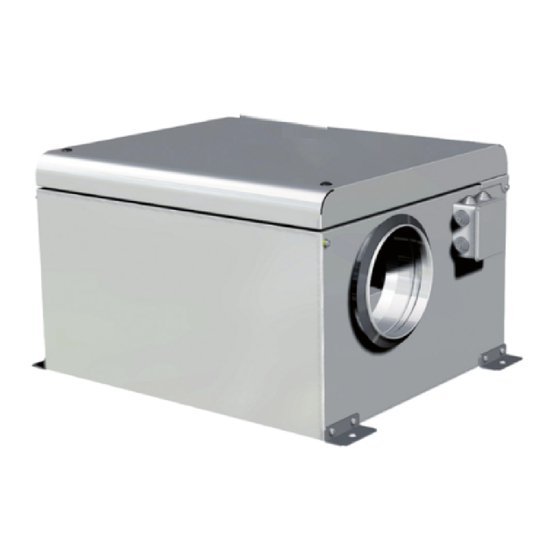
- Page 1 AKU / AKU EKO KF T120 / KF T120 EC KUB T120 / KUB EKO VKAP 3.0 / VKA EKO VKS / VKSA VSA 3.0 / VSA EKO VSV / VSV EKO AL / VSVI / VSVI EKO AL OPERATION, INSTALLATION & MAINTENANCE INSTRUCTIONS...
-
Page 2: Table Of Contents
1. CONTENT 1. CONTENT 2. SYMBOLS AND MARKING 3. SAFETY INSTRUCTIONS AND PRECAUTIONS 4. INFORMATION ABOUT THE PRODUCT 4.1. DESCRIPTION 4.2. DIMENSIONS AND WEIGHT 4.3. TECHNICAL DATA 4.4. OPERATING CONDITIONS 4.5. STANDARD PACKAGE OF COMPONENTS 4.6. DESCRIPTION OF COMPONENTS 5. INSTALLATION 5.1. -
Page 3: Symbols And Marking
2. SYMBOLS AND MARKING Warning – pay attention Additional information Apply the technical label on the unit (in an easily accessible location) or on the dashed location of the technical manual to keep the important information about the unit. Fig. 2.1 Technical label 1 - Logo;... - Page 4 Fig. 2.8 Fig. 2.9 direction direction Fig. 2.10 VSA 3.0 / VSA EKO technical label place Fig. 2.11 VSV / VSV EKO / VSV EKO AL technical label place Fig. 2.12 VSVI / VSVI EKO / VSVI EKO AL technical label place NOTE.
-
Page 5: Safety Instructions And Precautions
3. SAFETY INSTRUCTIONS AND PRECAUTIONS Read these instructions very carefully before installing and using this equipment. Installation, connection and maintenance should be carried out Main safety rules Danger • parts of the device have stopped. • Make sure that the fans are not accessible through air ducts or branch openings. •... -
Page 6: Information About The Product
The fans are designed for the use in the ventilation and air conditioning systems to supply / extract from a room the clean air only (free of chemical Not suitable for operation in pools, saunas and other similar premises. 4.2. DIMENSIONS AND WEIGHT Fig. 4.2.1 AKU / AKU EKO Fig. 4.2.2 AKU 700x400 EKO | EN FANS v2024.1... - Page 7 [mm] [mm] [mm] [mm] [mm] [mm] [mm] [mm] ØD [mm] [mm] Weight [kg] 13,6 13,5 13,8 17,3 AKU EKO 700 X 400 700 X 400 S [mm] [mm] [mm] [mm] [mm] [mm] [mm] [mm] [mm] [mm] [mm] [mm] [mm] [mm]...
- Page 8 Fig. 4.2.3 KF T120 / KF T120 EC KF T120 160-4 L3 180-4 L3 200-4 L3 225-4 L3 250-4 L3 280-4 L3 315-4 L3 355-4 L3 400-4 L3 [mm] [mm] [mm] [mm] [mm] [mm] [mm] [mm] ØD [mm] [mm] [mm] [mm] [mm] Weight...
- Page 9 Fig. 4.2.4 KUB T120 Fig. 4.2.5 KUB EKO KUB T120 355-4 L3 400-4 L3 450-4 L3 500-4 L3 560-4 L3 630-4 L3 [mm] [mm] [mm] [mm] [mm] [mm] ØD [mm] [mm] Weight [kg] KUB EKO 50-355 67-400 67-500 80-560 80-630 100-630 [mm] 1000...
- Page 10 Fig. 4.2.6 VKS Fig. 4.2.7 VKSA Fig. 4.2.8 VSA / VSA EKO | EN FANS v2024.1...
- Page 11 400- 400- 500- 500- 500- 500- 600- 600- 600- 600- 700- 800- 800- 1000- 200-4 200-4 250-4 250-4 300-4 300-4 300-4 300-4 350-4 350-4 400-4 500-4 500-6 500-4 [mm] [mm] 1040 [mm] [mm] 1000 [mm] [mm] [mm] 1020 Weight [kg] 400- 400- 500-...
- Page 12 Fig. 4.2.9 VSV / VSV AL / VSV AL EKO Fig. 4.2.10 VSVI / VSVI AL / VSVI AL EKO 250- 311-4 311-4 355-4 355-4 400-4 400-4 450-4 450-4 500-4 560-4 630-4 630-6 2SL1 [mm] 1065 1155 [mm] [mm] [mm] [mm] [mm] [mm]...
- Page 13 311-4 311-4 355-4 355-4 400-4 400-4 450-4 450-4 500-4 560-4 630-4 630-6 VSVI / VSVI AL [mm] 1265 [mm] [mm] [mm] [mm] [mm] [mm] [mm] [mm] [mm] 1265 Weight [kg] 311-L1 311-L1 355-L1 355-L1 400-L1 400-L1 450-L3 450-L3 500-L3 500-L3 560-L3 560-L3 630-L3 630-L3 VSVI EKO AL...
-
Page 14: Technical Data
Fig. 4.2.11 VKAP 3.0 / VKA EKO VKAP 3.0 100 LD 100 MD 125 LD 125 MD 150 LD 160 LD 160 MD 200 LD 200 MD 250 LD 250 MD 315 LD 315 MD [mm] [mm] [mm] ØD [mm] [mm] Weight [kg]... - Page 15 AKU EKO 700X400 700X400 S phase/voltage [50 Hz/VAC] ~1 / 230 ~1 / 230 ~1 / 230 ~1 / 230 ~1 / 230 ~1 / 230 ~1 / 230 [kW/A] 0,05 / 0,4 0,08 / 0,75 0,17 / 1,4 0,17 / 1,4...
- Page 16 VKAP 3.0 100 LD 100 MD 125 LD 125 MD 150 LD 160LD 160 MD 200 LD phase/voltage [50 Hz/VAC] ~1 / 230 ~1 / 230 ~1 / 230 ~1 / 230 ~1 / 230 ~1 / 230 ~1 / 230 ~1 / 230 [kW/A] 0,07 / 0,3...
- Page 17 VSA 3.0 190 S 190 L 220 S 220 M 225 L 250 L phase/voltage [50 Hz/VAC] ~1 / 230 ~1 / 230 ~1 / 230 ~1 / 230 ~1 / 230 ~1 / 230 [kW/A] 0,05 / 0,2 0,07 / 0,3 0,07 / 0,28 0,1 / 0,5 0,14 / 0,6...
-
Page 18: Operating Conditions
Not suitable for installation in living rooms: additional noise insulation required. 4.4. OPERATING CONDITIONS VSV / VSVI / AKU / KF T120 / KUB T120 / VKAP 3.0 / VKS / VSA / VSV EKO VSVI EKO AKU EKO KF T120 EC... -
Page 19: Description Of Components
4.6. DESCRIPTION OF COMPONENTS Fig. 4.6.1 AKU / AKU EKO Fig. 4.6.2 KF T120 Fig. 4.6.3 KF T120 EC Fig. 4.6.4 KUB T120 Fig. 4.6.5 KUB EKO Fig. 4.6.6 VKAP 3.0 / VKA EKO Fig. 4.6.7 VKS Fig. 4.6.8 VKSA Fig. -
Page 20: Installation
[mm] [mm] [mm] [mm] [PCS.] AKU 125 1900 1200 AKU 160 1900 1200 AKU 200 D AKU 200 M 1900 1200 AKU 250 D AKU 250 M AKU 250 S AKU 315 D 1050 AKU 315 M AKU 400 D... - Page 21 Dimensions of a single package Dimensions of a multi-package Max. number of transported packages [mm] [mm] [mm] [mm] [mm] [mm] [PCS.] KF T120 250-4 L3 KF T120 280-4 L3 KF T120 315-4 L3 KF T120 355-4 L3 1130 KF T120 400-4 L3 1130 KF T120 EC F 160 KF T120 EC F 180...
- Page 22 Dimensions of a single package Dimensions of a multi-package Max. number of transported packages [mm] [mm] [mm] [mm] [mm] [mm] [PCS.] VSA 190 1900 1200 VSA 220 1900 1200 VSA 225 2200 1200 VSA 250 1900 1200 VSA 190 EKO 2200 1200 VSA 220 EKO...
-
Page 23: Unpacking
To prevent damage to the casing, only a product placed on a pallet should be lifted. 5.3. UNPACKING Accessories may be packed together with the product. Prior to transporting the unit, the accessories should be unpacked • • Before commencing the installation of the unit, please check if all ordered equipment has been delivered. Any deviation from the ordered equip- ment list must be reported to the product supplier. -
Page 24: Mounting
• During installation, enough space must be retained for opening and cleaning the impeller. IMPORTANT. The fan should be installed only in such a way that the entire surface of the fan fully adheres to the surface of the installation. AKU / AKU EKO • •... - Page 25 Fig. 5.5.5 Mounting Fig. 5.5.6 Maintenance door removal Fig. 5.5.7 Changing the fan's maintenance door side KF T120 / KF T120 EC KUB T120 / KUB EKO • We recommend using a vibration isolating gasket. • • Fig. 5.5.8 Changing the maintenance side Fig.
- Page 26 VKAP 3.0 / VKA EKO • The fan can be mounted in any position. Fig. 5.5.11 Fig. 5.5.12 Connection to the duct using the clamp VKS / VKSA • The fan can be installed vertically or horizontally. • • thermo-contact leads and protectors. If a speed controller is used, a separate thermo-contact relay is not needed. •...
- Page 27 Fig. 5.5.15 Fig. 5.5.16 or ceiling Fig. 5.5.17 Mounting using special acces- Fig. 5.5.18 Enough space must be retained for opening and cleaning the impeller sories – adaptors AIR DUCT CONNECTION Fig. 5.5.19 Air duct connection CHIMNEY INSTALLATION • • •...
- Page 28 VSA 3.0 / VSA EKO • Fig. 5.5.21. • • Attach the fan to the roof chimney. • • Fig. 5.5.21 Mounting and installation Fig. 5.5.22 Mounting using accessories VSV / VSV EKO AL / VSVI EKO AL • Fig. 5.5.23. •...
-
Page 29: Connection Of The Air Ducts
Fig. 5.5.25 Mounting 5.6. CONNECTION OF THE AIR DUCTS • • • pressure and noise level, you can increase the diameter. • In order to reduce the level of noise in the air supply system, install silencers (see the chapter on air supply system installation). •... -
Page 30: Start-Up Recommendations
200 M 250 D 250 M 250 S Mains fuse 315 D 315 M 400 D 400 S Mains fuse AKU EKO 700X400 700X400 S Mains fuse 1,5A KF T120 EC B 315 B 355 B 400 F 160 F 180... -
Page 31: Pre Start-Up Recommendations Of The Unit (In The Presence Of The End-User)
VSV / VSVI / VSVI AL 250-2SL1 311-4 L1 311-4 L3 355-4 L1 355-4 L3 400-4 L1 400-4 L3 450-4 L1 450-4 L3 Mains fuse 1,5A 1,5A VSV / VSVI / VSVI AL 500-4 L3 560-4 L3 630-4 L3 630-6 L3 Mains fuse VSV EKO AL / VSVI EKO 311-L1... -
Page 32: Maintenance
6.3. COVER OPENING Fig. 6.3.1 AKU / AKU EKO Fig. 6.3.2 KF T120 / KF T120 EC Fig. 6.3.3 KUB T120 / KUB EKO Fig. 6.3.4 VKAP 3.0 / VKA EKO Fig. -
Page 33: Fan Maintenance
• Make sure the impeller is free of any obstacles. • • Prior to commencing any maintenance or repair works, make sure the unit is disconnected from the power source. Fig. 6.4.1 AKU / AKU EKO FANS v2024.1 EN |... - Page 34 Fig. 6.4.2 KF T120 / KF T120 EC Fig. 6.4.3 VKAP 3.0 / VKA EKO Fig. 6.4.4 VKS / VKSA Fig. 6.4.5 VSA 3.0 / VSA EKO | EN FANS v2024.1...
-
Page 35: Fan Speed Control
Fig. 6.4.6 VSV / VSV EKO / VSV EKO AL Fig. 6.4.7 VSVI / VSVI EKO / VSVI EKO AL 7. FAN SPEED CONTROL "PIPING AND INSTRUMENTATION DIAGRAM". "UNICON CPG-..AV OPERATING INSTRUC- TIONS" (L-BAL-E253). FANS v2024.1 EN |... -
Page 36: Connection Of Accessories
8. CONNECTION OF ACCESSORIES 8.1. CONNECTION OF EC FAN SPEED CONTROLLERS AKU EKO, KF T120 EC, KUB EKO, VKA EKO, VSA EKO, VSV EKO AL, VSVI EKO AL. These fans can be connected with 0-10VDC fan speed controllers: MTP or SMT. •... -
Page 37: Connection Of Ac Fan Speed Controllers
3x400VAC voltage) availability of controllers: SPEED CONTROLLER FAN UNITS ETY / MTY * AKU, VKAP 3.0, VKS L1, VKSA L1, VSA 3.0, VSV L1, VSVI L1, VSVI L1 AL TGRV TGRT VKS L3, VKSA L3, VSV L3, VSVI L3, VSVI L3 AL... - Page 38 • Fig. 8.2.3 ACS380 pinout and connection example | EN FANS v2024.1...
-
Page 39: Connection Of On/Off Safety Switch
8.3. CONNECTION OF ON/OFF SAFETY SWITCH Fig. 8.3.1 FANS v2024.1 EN |... -
Page 40: Electrical Wiring Diagrams
9. ELECTRICAL WIRING DIAGRAMS "TECHNICAL DATA" For the latest version of diagrams, check under the units terminal block cover. GENERAL COLOUR CODING Black Grey White Blue Orange Green – BK; U – BU; TB – BN – BK; U – BU; Z – BN. –... - Page 41 TK TK TK TK U1 – BN; U2 – RD; V1 – BU; V2 – GY; W1 – BK; W2 – OG; TK FANS v2024.1 EN |...
- Page 42 U1 – BN; U2 – BK; V1 V2 –RD; W1 – GN; W2 – BU; TK – YE. Harness | EN FANS v2024.1...
- Page 43 Harness GENERAL COLOUR CODING Black Grey White Blue Orange Green FANS v2024.1 EN |...
-
Page 44: Possible Faults And Troubleshooting
10. POSSIBLE FAULTS AND TROUBLESHOOTING FAILURE CAUSE EXPLANATION/CORRECTIVE ACTIONS No supply voltage The unit is not operating leakage relay is active (if installed by the installer) | EN FANS v2024.1... -
Page 45: Ecodesign Data Table
0,65 0,65 0,65 0,65 Declared maximum external leakage rates ErP Compliance 2018 2018 2018 2018 2018 Internet address for disassembly instructions AKU EKO 700X400 700X400 S NRVU/ NRVU/ NRVU/ NRVU/ NRVU/ NRVU/ NRVU/ Topology Type of drive (fan) Variable Variable... - Page 46 VKAP 3.0 100 LD 100 MD 125 LD 125 MD 150 LD 160 LD 160 MD Climate zone [ kWh/m -24,9 -24,3 -23,7 -25,2 -25,7 -25,5 consumption (SEC) SEC Class Average [ kWh/a ] [ kWh/a ] 2830 2830 2830 2830 2830 2830...
- Page 47 KUB EKO 50-355 67-400 67-500 80-560 80-630 100-630 Topology NRVU/VU NRVU/VU NRVU/VU NRVU/VU NRVU/VU NRVU/VU Type of drive (fan) Variable Variable Variable Variable Variable Variable /s ] 0,466 0,833 1,414 1,661 2,574 2,887 [ W ] 1273 1521 2984 2895 Face velocity [ m/s ] Nominal external pressure...
- Page 48 VSA 3.0 190 L 190 S 220 M 220 S 225 L 250 L Climate zone [ kWh/m -25,7 -24,7 -26,1 -25,2 -26,4 -24,8 consumption (SEC) SEC Class Average [ kWh/a ] 88,1 77,2 [ kWh/a ] 2830 2830 2830 2830 2830 2830...
- Page 49 VSV / VSVI / VSVI AL 311-4 L1 355-4 L1 355-4 L3 400-4 L1 400-4 L3 Topology NRVU/UVU NRVU/UVU NRVU/UVU NRVU/UVU NRVU/UVU Type of drive (fan) Multi-speed Multi-speed Multi-speed Multi-speed Multi-speed /s ] 0,36 0,61 0,457 0,64 0,631 [ W ] Face velocity [ m/s ] Nominal external pressure...
-
Page 50: Declaration Of Conformity
12. DECLARATION OF CONFORMITY Manufacturer SALDA, UAB LT-78109 Šiauliai, Lithuania Tel.: +370 41 540415 www.salda.lt FAN* Machinery Directive 2006 / 42 / EC Low Voltage Directive 2014 / 35 / EU EMC Directive 2014 / 30 / EU RoHS 2 Directive 2011 / 65 / EU Energy labeling of residential units Nr. -
Page 51: Warranty
The manufacturer reserves the right to change this technical passport at any time without prior notice if some typographic errors or inaccurate information is found, as well as after improving the apps and/or the devices. Such changes will be original device. The newest manual version is available at https://select.salda.lt 13.1. LIMITED WARRANTY COUPON 24 months* .................................. - Page 52 Date Fan cleaning Once per year** * - Look at the product label. ** - At least. NOTE. The customer shall be required to complete the Product Maintenance Table. MANUALS IN OTHER LANGUAGES https://select.salda.lt/file/ https://select.salda.lt/file/ https://select.salda.lt/file/ https://select.salda.lt/file/ https://select.salda.lt/file/ fans-de fans-dk...
Need help?
Do you have a question about the AKU and is the answer not in the manual?
Questions and answers