
Related Manuals for Kongsberg EM 712


Summary of Contents for Kongsberg EM 712
- Page 1 Kongsberg EM 712 Multibeam echo sounder Installation manual 401027/A July 2015 © Kongsberg Maritime AS...
- Page 2 Kongsberg Maritime AS. The document, or any part of it, may not be translated to any other language without the written approval from Kongsberg Maritime AS.
-
Page 3: Table Of Contents
TX Unit description....................11 RX Unit description....................11 EM 712 Processing Unit description..............12 Hydrographic Work Station description..............12 PREPARATIONS ..............14 Necessary tools and equipment for EM 712 installation ..........14 Requirements for shipyard worker skills .................15 Sonar room requirements....................16 Environment ......................16 Watertight integrity....................16 Size and access .......................17... - Page 4 Cable plan, Transmitter Unit ..................40 Cable plan, Receiver Unit, 0.5 degree..............42 Topside cable plan ....................45 List of EM 712 cables ......................45 Cable drawings and specifications ...................50 RS–232 serial line using three 3 wires and RJ45 connector ........51 RS-422 serial line using five wires and RJ45 connector ........52 1PPS (One pulse per second) using a coax cable ...........54...
-
Page 5: About This Manual
The purpose of this manual is to provide the information and basic drawings required for the physical installation of the EM 712. For more detailed information about the practical use of the EM 712, refer to the Operator manual and/or the Reference manual. -
Page 6: Kongsberg Em
You must follow the instructions given in this manual. If not it may affect the warranty. Kongsberg Maritime AS will accept no responsibility for any damage or injury to the system, vessel or personnel caused by equipment that has been incorrectly installed or maintained, or by drawings, instructions or procedures that have not been prepared by us. -
Page 7: Kongsberg Em 712
System units, page 10 System diagram 0.5 x 0.5 degrees system The system diagram identifies the main components of a basic EM 712 system, as well as the key connections between the units. Interface capabilities and power cables are not shown. - Page 8 Kongsberg EM 712 (CD020106_100_002) Hydrographic Work Station (HWS) Interfaces: • Sound speed sensor • Tide • Center depth output Processing Unit (PU) Processing Unit interfaces: • Positioning systems • Attitude (roll, pitch and heave) • Velocity • Heading • Clock...
- Page 9 Kongsberg EM 712 Processing Unit special interfaces: • Trigger input/output • Clock synchronization (1PPS) TX Unit RX Unit Transmit transducer Receive transducer 401027/A...
-
Page 10: System Units
The receiver transducer array should be aligned 90º on the keel. Both transducers should be horizontal on a plane on the keel. The EM 712 can use two sizes of transmit (TX) and receive (RX) modules: • : TX1 1 degree transmit transducer •... -
Page 11: Tx Unit Description
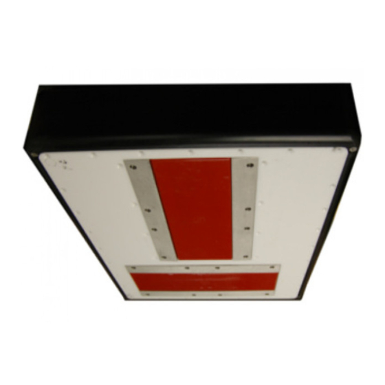
• Do not use high pressure water, sand blasting, metal tools or strong solvents to clean the transducer face. TX Unit description The EM 712 TX (transmit) Unit has all transmit electronics. The EM 712 TX Unit is a wall-mounted steel cabinet with integrated shock and vibration absorbers. It holds the circuit boards for transmission. -
Page 12: Em 712 Processing Unit Description
Ethernet cable connects the TX Unit to the Processing Unit. EM 712 Processing Unit description The EM 712 Processing Unit is provided to process the signals to and from the Transmitter and Receiver Units. The EM 712 Processing Unit is an industrial computer using both COTS (commercial off-the-shelf) components and custom made components. - Page 13 Kongsberg EM 712 In this publication, the computer is referred to as the Hydrographic Work Station. 401027/A...
-
Page 14: Preparations
Necessary tools and equipment for EM 712 installation The installation of the EM 712 must take place in dry dock, and the work must be done by a qualified shipyard. In order to do the EM 712 installation, all necessary tools and equipment for mechanical hull work, cabinet installation and electrical wiring must be available. -
Page 15: Requirements For Shipyard Worker Skills
Preparations Requirements for shipyard worker skills The installation of the EM 712 is a demanding task. It is very important that the shipyard workers involved in the installation tasks are competent. As a minimum, the following certified craftsmen must be available: •... -
Page 16: Sonar Room Requirements
Bilge pump and decking, page 18 Environment The EM 712 cabinets must be installed in a dry and dust-free environment. The cabinets are not fully protected against humidity, dust or water. Observe the environmental specifications related to the EM 712 cabinets. -
Page 17: Size And Access
The sonar room must be dimensioned to house all the relevant cabinets that comprise the EM 712 system. The room must not be used for any other heavy machinery. -
Page 18: Electrical Installations, Cables And Communication
Kongsberg EM 712 vent pipes to divert moisture to the bilge. On the main deck, the best ventilation is provided when the outlet pipe is at least four meters higher than the inlet pipe. To keep out sea water, rain and spray, the ventilation pipes should be fitted with goosenecks or a equivalent design. -
Page 19: Where To Install The Transducer
Mount the transducer deep In order to achieve the best possible EM 712 performance, mount the transducer as deep as possible under the vessel’s hull. Consider the situations when the vessel is unloaded, and when it is pitching in heavy seas. -
Page 20: Avoid Protruding Objects
Choose a position far away from the bow thruster(s) Bow thruster propellers are extremely noisy. When in operation, the noise and cavitation bubbles created by the thruster may make your EM 712 system useless, almost no matter where the transducer is installed. 401027/A... -
Page 21: Summary And General Recommendations
Preparations And when not in operation, the tunnel creates turbulence. If your vessel is pitching, the tunnel may be filled with air or aerated water in the upper position and release this in the lower position. In general, all transducers must therefore be placed well away from the bow thruster. In most cases, a location forward of the bow thruster is advantageous. -
Page 22: Acoustic Noise
Kongsberg EM 712 Acoustic noise As with any other hydroacoustic systems, the quality of the EM 712 presentations are subject to unwanted acoustic noise. The echoes from any large and small target must be detected inside the noise. It is important that we keep this noise level as low as possible in order to obtain long range and dependable interpretations of the echoes. -
Page 23: Self Noise
Preparations signal than noise. While SNR is commonly quoted for electrical signals, it can be applied to any form of signal [...]. http://en.wikipedia.org/wiki/Signal_to_noise_ratio (September 2013) For active sonar and echo sounder systems, the signal is the echo that we want to know something about, while the noise is any unwanted signals or disturbances. - Page 24 Kongsberg EM 712 • Cavitation • : Laminar flow, turbulent flow, bubbles, etc Flow noise • : Loose parts Rattle noise • : Other hydroacoustic systems on your own vessel Interferences We will here go into some details in order to analyse the different sources of self noise on a vessel and how they may influence upon the noise level of the hydroacoustic instruments.
- Page 25 Preparations Cavitation Cavitation usually occurs more willingly in air filled water and the occurrence is dependent on the hydrostatic pressure. Cavitation is a severe source of noise. The noise is made when the voids implode. Cavitation noise often occurs at the propeller and near extruding objects at higher speeds.
-
Page 26: Ambient Noise
At higher frequencies – where rather wide bandwidths are necessary – the noise from components, transistors or other analogue electronic may be a limiting factor. Some means to reduce acoustic noise Careful planning of the EM 712 installation may reduce the acoustic noise. 401027/A... - Page 27 Note The information here must be considered as general advice. Each EM 712 installation must be handled separately depending on the hull design and the other electrical and mechanical systems installed on the vessel.
-
Page 28: Vessel Coordinate System
• Make sure that all units are properly grounded, as this is important to avoid electrical noise. • You must use shielded cables with correct grounding. • Separate EM 712 cables from other cables with heavy currents or transients. • Place all high voltage power cables in metal conduits. Vessel coordinate system The vessel coordinate system is established to define the relative physical locations of systems and sensors. - Page 29 Preparations Example If you wish to measure the actual water depth, you will need to know the vertical distance from the echo sounder transducer to the water line. Since the vessel’s displacement changes with the amount of cargo, fuel etc, the physical location of the water line on the hull must either be measured at a regular basis, or measured with a second sensor.
- Page 30 Kongsberg EM 712 Alternative origins If necessary, other origin locations may be defined for specific products or purposes. One example is the Navigation Reference Point that is frequently used. Whenever a vessel is surveyed to establish accurate offset information, the surveyor may also establish an alternative origin location.
-
Page 31: Installing The Transducer
Transducer installation, page 31 Transducer installation Installation of the EM 712 transducers are similar to the EM 710 transducers. For details about the installation of the EM 712 transducers please refer to the EM 710 Installation Manual document number: 164851. 401027/A... -
Page 32: Installing The Em 712 Hardware Units
Installing the TX Unit The EM 712 TX Unit is normally positioned in a dedicated room in the vicinity of the transducer. The physical length of the cables limit the distance between the transducers and the TX Unit. - Page 33 Installing the EM 712 hardware units 190 330 ø11 (CD020106_001_001) Procedure Prepare the installation site. Observe the general sonar room requirements. Provide ample space around the cabinet to allow for inspection, maintenance and parts replacement. Make sure that the space allows the cabinet door to be fully dismounted for unobstructed access to its internal parts.
-
Page 34: Installing The Rx Unit
Kongsberg EM 712 Installing the RX Unit The EM 712 RX Unit is normally positioned in a dedicated room in the vicinity of the transducer. The physical length of the cables limit the distance between the transducers and the RX Unit. - Page 35 Installing the EM 712 hardware units Mark the location of the holes for the upper and lower shock absorber on the bulkhead. Drill 9-mm holes, three (3) for each shock absorber. Note Always check on the other side of the bulkhead before drilling holes Mount the cabinet to the bulkhead with six (6) M8 bolts.
-
Page 36: Cable Layout And Interconnections
Cable layout and interconnections Cabling principles, cable plans and drawings, as well as relevant procedures, are provided. Topics Read this first, page 37 Cable plans, page 38 List of EM 712 cables, page 45 Cable drawings and specifications, page 50 401027/A... -
Page 37: Read This First
Cable layout and interconnections Read this first Detailed information about cable specifications, termination and connectors is provided. Unless otherwise specified, all cables are supplied by Kongsberg Maritime as a part of the EM 712 delivery. Note All electronic installations and corresponding wiring must be in accordance with the vessel's national registry and corresponding maritime authority and/or classification society. -
Page 38: Cable Plans
Kongsberg EM 712 Cable plans Topics Cable plan, Processing Unit, page 39 Cable plan, Transmitter Unit, page 40 Cable plan, Receiver Unit, 0.5 degree, page 42 Topside cable plan, page 45 401027/A... -
Page 39: Cable Plan, Processing Unit
Cable layout and interconnections Cable plan, Processing Unit The processing unit cables include those used to connect the EM 712 processing unit to AC mains power, and to the transmitter and receiver units. One Ethernet cable is used to connect the processing unit to the Hydrographic Work Station. -
Page 40: Cable Plan, Transmitter Unit
Kongsberg EM 712 Cable plan, Transmitter Unit The transmitter (TX) Unit cables include those used to connect the EM 712 TX Unit(s) to AC mains power, to the receiver (RX) Unit, to the Processing Unit and to the transducers. If there are more than one TX Unit they have to be connected to each other with a fibre optic cable. - Page 41 Transmit Transducer (TX) 1 Transmit Transducer (TX) 2 Cables identified with an asterisk (*) are provided with the standard EM 712 delivery. The illustration shows the TX transducer arrays mounted in the default orientation, with the cables pointing towards starboard.
-
Page 42: Cable Plan, Receiver Unit, 0.5 Degree
Cable plan, Receiver Unit, 0.5 degree The receiver (RX) Unit cables include those used to connect the EM 712 RX Unit(s) to AC mains power, to the transmitter (TX) Unit, to the Processing Unit and to the transducers. If there are more than one RX Unit they have to be connected to each other with a fibre optic cable. - Page 43 Cable layout and interconnections ETHERNET POWER ETHERNET POWER C43* C67* C42* C65* C66* C64* SYNC SYNC C45* C46* Starboard RX1-1* RX2-1* RX1-2* RX2-2* RX1-3* RX2-3* RX1-4* RX2-4* (CD020106_202_002) 401027/A...
- Page 44 Receive Transducer (RX) 1 Receive Transducer (RX) 2 Cables identified with an asterisk (*) are provided with the standard EM 712 delivery. The illustration shows the RX transducer arrays mounted in the default orientation, with the cables pointing towards stern.
-
Page 45: Topside Cable Plan
Cables identified with an asterisk (*) are provided with the standard EM 712 delivery. List of EM 712 cables A set of cables is required to connect the EM 712 system units to each other, to the relevant power source(s), and to peripheral devices. - Page 46 Kongsberg EM 712 Cable Signal From / To Min. requirements AC power Ship supply / Hydrographic Work Station power supply Ground Ground / Hydrographic Work Station Ethernet Processing Unit / Hydrographic See comment 4 Work Station Serial Hydrographic Work Station \...
- Page 47 Cable layout and interconnections Cable Signal From / To Min. requirements Remote control Last Transmitter Unit (TX Unit) / Receiver Unit (RX Unit) 1 Remote control Receiver Unit (RX Unit) 1 / Receiver Unit (RX Unit) 2 AC power Ship supply / Transmitter Unit See comment 9 (TX Unit) 1 Ground...
- Page 48 Kongsberg EM 712 Cable Signal From / To Min. requirements TX2–3 Transducer TX Transducer 2 / Transmitter See comment 11 Unit (TX Unit) TX2–4 Transducer TX Transducer 2 / Transmitter See comment 11 Unit (TX Unit) TX2–5 Transducer TX Transducer 2 / Transmitter...
- Page 49 Standard cable length is 15 meters. Identifying EM 712 cables on a project cable drawing The EM 712 is often a part of a project delivery. For such deliveries, project cable drawings are established to show all main cables, and how the various products interconnect.
-
Page 50: Cable Drawings And Specifications
Kongsberg EM 712 Cable drawings and specifications Relevant cables and connections required for the EM 712 are described in detail. Topics RS–232 serial line using three 3 wires and RJ45 connector, page 51 RS-422 serial line using five wires and RJ45 connector, page 52... -
Page 51: Rs-232 Serial Line Using Three 3 Wires And Rj45 Connector
Cable layout and interconnections RS–232 serial line using three 3 wires and RJ45 connector An RS-232 serial line connection using three –3– wires and NMEA telegrams is probably the most common way to connect the EM 712 to external devices. GROUND GROUND... -
Page 52: Rs-422 Serial Line Using Five Wires And Rj45 Connector
Kongsberg EM 712 RS-422 serial line using five wires and RJ45 connector An RS-422 serial line connection can transmit data at rates as high as 10 million bits per second, and may be sent on cables as long as 1500 meters. - Page 53 Cable layout and interconnections Minimum cable requirements • : 2 x 4 x 0.5 mm² Conductors • : Overall braided Screen • : 60 V Voltage • : Defined by the plugs Maximum outer diameter If you need to install a very long serial line cable, increase the cross section. 401027/A...
-
Page 54: 1Pps (One Pulse Per Second) Using A Coax Cable
Kongsberg EM 712 1PPS (One pulse per second) using a coax cable The Processing Unit is equipped with a 1PPS signal input for clock synchronization. This cable must be provided by the installation shipyard. 1PPS cable Male BNC connector Ground... - Page 55 Cable layout and interconnections 12V - 1.2V(U ) 10.8 =1080 10mA 0.010 R =1080-330=750 An added resistor of 750Ω and minimum 0.1 Watt must be used. Note The input signals must not be negative, i.e. no RS-232 signals can be used for these inputs.
-
Page 56: Remote Control
Kongsberg EM 712 Remote control The Processing Unit can be switched on/off with a remote switch. This switch is connected to a 9–pin D-connector on the Processing Unit. STANDBY 12 V STANDBY GND (CD0806_701_010) (CD0801_001_002) Local connection, male 9–pin D-connector Connection to remote lamp and on/off switch Female 9–pin D-connector... -
Page 57: Remote Control Using K-Rem
Cable layout and interconnections Remote Control using K-Rem The Processing Unit can be switched on/off with a remote switch. This switch is connected to a 9–pin D-connector on the Processing Unit. A dedicated junction box with on/off switches and light indication has been designed for this purpose (K-Rem). STANDBY 12 V STANDBY 12 V STANDBY GND... -
Page 58: Dummy Plug For Not Using Remote Control
Optical isolated input High • : This is an output signal from the EM 712 to the synchronization Ready To Transmit system that goes active when the EM is ready to transmit. The signal is inactive when the echo sounder is transmitting, receiving or processing samples. - Page 59 Cable layout and interconnections • : The EM 712 issues a trig out signal. The trig out signal starts before the first Trig out transmit pulse and is terminated after the end of the last transmit pulse. • The EM 712 can be triggered by an external signal that will cause the echo Trig in: sounder to ping.
- Page 60 Kongsberg EM 712 Optical isolated input signals Input from external system Processing Unit input circuitry Trig In+ The input current must U =1.2V be approximately 10 mA. Depending on your input signal Trig In- additional resistance must be applied to achieve the required CD020104_102_001 input current.
- Page 61 Cable layout and interconnections External power CBMF board RTS out+ Trig out+ Customer input RTS out- Trig out- cd020104_102_002 Power Resistor value Minimum effect 0.1 W 0.38 kΩ 12 V 1.08 kΩ 0.15 W 24 V 0.25 W 2.28 kΩ Note To avoid ground loops and damage of the EM 2040 electronics caused by external connections, all connections are optically isolated.
-
Page 62: Drawing File
Kongsberg EM 712 Drawing file 401027/A... -
Page 63: Em 712 Transmitter Unit Outline Dimensions
Drawing file EM 712 Transmitter Unit outline dimensions Drawing 396402. All measurements in mm. [396402] Rev .A The drawing is not in scale. 401027/A... -
Page 64: Em 712 Receiver Unit Outline Dimensions
Kongsberg EM 712 EM 712 Receiver Unit outline dimensions Drawing 396428. All measurements in mm. [396428] Rev .A The drawing is not in scale. 401027/A... -
Page 65: Processing Unit Dimensions
Drawing file Processing Unit dimensions Drawing 385422 482.5 Front V iew Rear V iew Side V Weight: 10.5 kg All measurements in mm. [385422] Rev .Pro01 The drawing is not in scale. CD12_385422_001_001 401027/A... -
Page 66: Hydrographic Work Station Outline Dimensions
Kongsberg EM 712 Hydrographic Work Station outline dimensions Drawing 378828 (2 pages) 401027/A... - Page 67 Drawing file Page 2 401027/A...
-
Page 68: Remote Control Unit (K-Rem) Outline Dimensions
Kongsberg EM 712 Remote Control Unit (K-REM) outline dimensions Drawing 370275 (2 pages) Top view 4 x M5 Front view 482.6 465.9 (19" rack) 4x M6 mounting holes Side view 4x M4 (both sides) All measurements in mm. [370275] Rev .A The drawing is not in scale. - Page 69 Drawing file Page 2 Top view 4 x PG9 - cable diameter 6.5 - 9 mm 4 x PG13.5 - cable diameter 12 - 15 mm Bottom view Ground connection 259.5 All measurements in mm. [370275] Rev .A The drawing is not in scale. CD12_ 370275 _001_002...
-
Page 70: Technical Specifications
Kongsberg EM 712 Technical specifications The technical specifications summarize the main functional and operational characteristics of the EM 712 system, as well as information related to power requirements, physical properties and environmental conditions. Note We are continuously working to improve the quality and performance of our products. - Page 71 • : Hewlett Packard Manufacturer (http://www.hp.com) • : HP8300H Model The standard computer from Hewlett Packard has been configured to fit the operational requirements of the EM 712. • Outline dimensions – : 384 mm Depth – : 337 mm Width –...
-
Page 72: Power Requirements
: 118 mm Height • : 28.5 kg (with 2 cables) Weight Power requirements The power specifications summarize the supply power requirements for the EM 712 system. Note The use of an uninterrupted power supply (UPS) is highly recommended. 401027/A... -
Page 73: Environmental Requirements
(http://www.hp.com) • : HP8300H Model The standard computer from Hewlett Packard has been configured to fit the operational requirements of the EM 712. • : 115/230 Vac / 47 to 63 Hz / single phase, selectable (nominal) Voltage requirement •... - Page 74 Kongsberg EM 712 Transceiver Unit TX Unit • : 0 to +50°C Operational temperature • : –30 to +70°C Storage temperature • : 93% relative non-condensing Relative humidity • : IP54 Ingress protection • Vibration – : 5 to 150 Hz Frequency range –...
- Page 75 Hydrographic Work Station ......45 TX Unit ........... 71 processing unit ........... 39 drawing receiver unit ..........43 1 pulse per second (1PPS) ......54 topside ............. 45 cables ............38 transmitter unit ........... 40 EM 712 system diagram ......... 8 cables 401027/A...
- Page 76 Kongsberg EM 712 external synchronization ........ 58 instructions ..........5 remote control ..........56 planning ........... 14 remote control using K-Rem ......57 preparations..........14 RS-232 serial line cable......... 51 requirements for installation workers ....15 RS-422 serial line cable......... 52 RX Unit ...........
- Page 77 Index weight ............. 71 propeller noise operating humidity cavitation..........25 computer ..........73 propellers Hydrographic Work Station ......73 transducer installation ........20 RX Unit ........... 74 protruding objects transceiver ..........74 avoid ............20 TX Unit ........... 74 operating temperature outline dimensions........
- Page 78 RX Unit ........... 74 system cables TX Unit ........... 74 list ............45 simplified system units EM 712 system diagram ......... 8 installation ..........32 size computer ..........66 Processing Unit .......... 65 Remote Control Unit (K-Rem)......68 RX Unit ........... 64 target audience sonar room ..........
- Page 79 Index outline dimensions........63 power requirements........73 weight and outline dimensions......71 turbulence protruding objects........20 turbulent flow..........25 TX unit cable plan ..........40 TX Unit brief description.......... 11 dimensions ..........71 installation ..........32 operating humidity........74 operating temperature ........74 operating voltage.........
- Page 80 ©2015 Kongsberg Maritime...
Need help?
Do you have a question about the EM 712 and is the answer not in the manual?
Questions and answers