Siemens SIMATIC ET 200eco PN M12-L System Manual
Distributed i/o system et 200eco pn
Hide thumbs
Also See for SIMATIC ET 200eco PN M12-L:
- Operating instructions manual (278 pages) ,
- Compact operating instructions (156 pages) ,
- System manual (92 pages)

Related Manuals for Siemens SIMATIC ET 200eco PN M12-L


Summary of Contents for Siemens SIMATIC ET 200eco PN M12-L
- Page 1 Edition 11/2023 System Manual SIMATIC ET 200eco PN M12-L Distributed I/O system ET 200eco PN support.industry.siemens.com...
- Page 2 Introduction Safety instructions SIMATIC New properties/functions ET 200eco PN Distributed I/O system Industrial cybersecurity ET 200eco PN M12-L System overview System Manual Mounting Connecting Configuring Commissioning Maintenance Technical specifications Safety-related shutdown Dimension drawings Accessories/spare parts 11/2023 A5E48753295-AG...
- Page 3 Note the following: WARNING Siemens products may only be used for the applications described in the catalog and in the relevant technical documentation. If products and components from other manufacturers are used, these must be recommended or approved by Siemens. Proper transport, storage, installation, assembly, commissioning, operation and maintenance are required to ensure that the products operate safely and without any problems.
-
Page 4: Table Of Contents
Table of contents Introduction............................Siemens Industry Online Support..................Industry Mall........................10 Guide to ET 200eco PN M12-L................... 10 1.3.1 Information classes ET 200eco PN M12-L................10 1.3.2 Basic tools........................1.3.3 S7 Port Configuration Tool (S7-PCT).................. 13 1.3.4 MultiFieldbus Configuration Tool (MFCT)................ - Page 5 Secure operation of I/O modules..................33 4.10 Secure operation of the power supply modules..............33 System overview..........................What are the SIMATIC ET 200eco PN M12-L distributed I/O devices?........34 Components........................36 Mounting............................39 Basics..........................39 Mounting without mounting rail..................40 Mounting with mounting rail....................
- Page 6 Table of contents 7.7.2 Optional markings......................65 7.7.3 Mounting identification labels................... 66 Configuring............................67 MultiFieldbus engineering....................Detect active fieldbus......................67 PROFINET IO........................68 8.3.1 Configuring the ET 200eco PN M12-L................68 8.3.2 Isochronous real-time communication................8.3.3 Isochronous mode......................70 8.3.4 Shared device........................
- Page 7 Table of contents Technical specifications........................93 11.1 Codes and approvals......................93 11.2 Certificates........................98 11.3 Standards and requirements..................... 99 11.4 Electromagnetic compatibility................... 100 11.5 Transport and storage conditions..................102 11.6 Mechanical and climatic ambient conditions..............102 11.7 Details on insulation, protection class, degree of protection and rated voltage....105 11.8 Use of the ET 200eco PN M12-L in Zone 2/Zone 22 hazardous areas........
-
Page 8: Introduction
Introduction Purpose of the documentation This documentation provides you with important information on configuring, installing, wiring and commissioning the SIMATIC ET 200eco PN M12‑L distributed I/O devices. The ET 200eco PN M12‑L I/O devices are the innovation of the proven product family ET 200eco PN. You can recognize the I/O devices of the new innovation level by the suffix M12-L. -
Page 9: Siemens Industry Online Support
• mySupport Your personal working area in Industry Online Support for messages, support queries, and configurable documents. This information is provided by the Siemens Industry Online Support in the Internet (http://www.siemens.com/automation/service&support). Distributed I/O system ET 200eco PN M12-L System Manual, 11/2023, A5E48753295-AG... -
Page 10: Industry Mall
Introduction 1.3 Guide to ET 200eco PN M12-L Industry Mall The Industry Mall is the catalog and order system of Siemens AG for automation and drive solutions on the basis of Totally Integrated Automation (TIA) and Totally Integrated Power (TIP). -
Page 11: Basic Tools
With the TIA Selection Tool , you can generate a complete order list from your product selection or product configuration. You can find the TIA Selection Tool on the Internet. (https://support.industry.siemens.com/cs/ww/en/view/109767888) SIMATIC Automation Tool You can use the SIMATIC Automation Tool to perform commissioning and maintenance activities on various SIMATIC S7 stations as bulk operations independent of TIA Portal. - Page 12 You can find SIEMENS PRONETA Basic on the Internet: (https://support.industry.siemens.com/cs/ww/en/view/67460624) SIEMENS PRONETA Professional is a licensed product that offers you additional functions. It offers you simple asset management in PROFINET networks and supports operators of automation systems in automatic data collection/acquisition of the components used through various functions: •...
-
Page 13: S7 Port Configuration Tool (S7-Pct)
SIMATIC S7-PCT The Port Configuration Tool (PCT) is a PC-based software for the parameter assignment of Siemens IO-Link Master modules and IO-Link devices from any manufacturer. You integrate IO-Link-devices using the standardized device description "IODD", which you get from the respective device manufacturer. S7-PCT supports version 1.0 and V1.1 of the IODD. -
Page 14: Simatic Technical Documentation
Online Support: Industry Online Support International https://support.industry.siemens.com/cs/ww/en/view/109742705 Watch this short video to find out where you can find the overview directly in Siemens Industry Online Support and how to use Siemens Industry Online Support on your mobile device: Quick introduction to the technical documentation of automation products per video ( https://support.industry.siemens.com/cs/us/en/view/109780491... - Page 15 Manuals, characteristics, operating manuals, certificates • Product master data You can find "mySupport" on the Internet. (https://support.industry.siemens.com/My/ww/en) Application examples The application examples support you with various tools and examples for solving your automation tasks. Solutions are shown in interplay with multiple components in the system - separated from the focus on individual products.
-
Page 16: Safety Instructions
Safety instructions Warnings in this document You can find explanations of the warnings used in this document in the "Legal information" section. Safety related icons for ET 200eco PN M12-L The following table explains the symbols located on the I/O device with the degree of protection IP65/IP67 and IP69K, on its packaging or in the accompanying documentation. -
Page 17: Intended Use
Safety instructions 2.5 Target group and personnel qualifications Symbol Meaning Note that a device of Protection Class III can only be supplied with a protective low voltage according to the standard SELV/PELV. IEC 60417‑1‑5180 "Class III equipment" Note that the device must be constructed and connected in accordance with EMC regulations. -
Page 18: Working On Electrical Parts
Safety instructions 2.7 Residual risks Working on electrical parts Only work on electrical parts if you are a qualified specialist (see section Target group and personnel qualifications (Page 17)). • Always observe the country-specific safety rules. • Notify all those who will be affected by the procedure. •... -
Page 19: Conductive Pollution
Safety instructions 2.7 Residual risks Maintenance • Only work on electrical parts if you are a qualified specialist (see section Target group and personnel qualifications (Page 17)). • Adhere to the protective measures for safe working on electrical parts (see section Working on electrical parts (Page 18)). -
Page 20: Unsafe Operating States
Safety instructions 2.9 Material damage 2.7.4 Unsafe operating states Unsafe operating states may result in personal injury of unknown extent. The following factors can be triggers: • Manipulation of the software, e.g. viruses, trojans or worms. Manipulation of the software, e.g. viruses, trojans or worms. •... - Page 21 Safety instructions 2.9 Material damage 2.9.2 Installation and connection Ensure for the connection that the overvoltage protection is sufficient. Installation/disassembly with voltage switched on • Install the ET 200eco PN M12‑L distributed I/O devices only with disconnected supply and load voltages. Refer to section Mounting (Page 39) •...
-
Page 22: New Properties/Functions
New properties/functions Changes compared to previous version What's new in the ET 200eco PN M12-L System Manual, 11/2023 edition compared to 08/2023 edition) What's new? What are the customer benefits? Where can I find the informa tion? New con Approval for hazardous areas According to the specifications in the informa Starting with section System tents tion for use, the I/O devices are suitable for... -
Page 23: Industrial Cybersecurity
Siemens' products and solutions undergo continuous development to make them more secure. Siemens strongly recommends that product updates are applied as soon as they are available and that the latest product versions are used. Use of product versions that are no longer supported, and failure to apply the latest updates may increase customers' exposure to cyber threats. -
Page 24: Security Update Notification
Introduction (Page 8) section. Set up notification of security updates To receive notifications about security updates, proceed as follows: 1. Register with mySiePortal (https://sieportal.siemens.com/en-ww/home). 2. Enter the keyword "Security" in the search engine. 3. Choose the "Search in Knowledge base" option. -
Page 25: Integrated Security Concept And Security Strategies
Integrated security concept and security strategies 4.4.1 Comprehensive security concept "Defense in Depth" With Defense in Depth, Siemens provides a multi-layer security concept that offers industrial plants comprehensive and far-reaching protection in accordance with the recommendations of the IEC 62443 international standard. - Page 26 Industrial cybersecurity 4.4 Integrated security concept and security strategies Siemens will provide you with information and support. Subscribe to the RSS feed (https://www.siemens.com/cert) for vulnerabilities. Register with mySiePortal (https://sieportal.siemens.com/en-ww/home) and create filters to be notified when important information is published. Consider using Siemens Cybersecurity Services.
-
Page 27: Operational Application Environment And Security Assumptions
Industrial cybersecurity 4.5 Operational application environment and security assumptions Consideration of the risks posed by cyber attacks in the Threat and Risk Assessment (TRA) Make an inventory of all software, hardware, and infrastructure devices, in order to identify risks to the location or organization. Incident response procedures must be incorporated into all IT and manufacturing processes. -
Page 28: Requirements For The Operational Application Environment And Security Assumptions
4.5 Operational application environment and security assumptions 4.5.2 Requirements for the operational application environment and security assumptions Siemens recommends the following security measures: • Conducting a threat and risk assessment (as part of security management) • Network security concepts – Network segmentation –... -
Page 29: Security Properties Of The Devices
Security properties of the devices The security properties of the individual devices are listed in the Equipment Manuals. Secure operation of the system This section describes measures recommended by Siemens to protect your system from manipulation and unauthorized access. 4.7.1... -
Page 30: Handling Of Sensitive Data
Siemens ProductCERT If Siemens identifies or fixes security gaps (Vulnerabilities) in the products, this will be published in the Security Advisories. You can find the documents for SIMATIC on the following Siemens AG Web page: Siemens ProductCERT and Siemens CERT (https://new.siemens.com/global/en/products/services/cert. -
Page 31: Data Backup
– Measures – Availability – Etc. • Report possible vulnerabilities yourself at (https://new.siemens.com/global/en/products/services/cert.html#ContactInformation) Set up an RSS feed to receive notifications about security-related topics. 4.7.6 Data backup Secure your configuration and parameter settings so that you can quickly restore this data if needed. -
Page 32: Securely Removing Data
Industrial cybersecurity 4.7 Secure operation of the system 4.7.8.1 Securely removing data Before disposing of components of your automation system, you should securely delete all data from the storage media of these components. How to securely delete data from the devices so that it cannot be recovered is described below. -
Page 33: Recycling And Disposal
Industrial cybersecurity 4.10 Secure operation of the power supply modules For more information on resetting the I/O device to factory settings, refer to the section Resetting an interface module to factory settings (Page 90). NOTE TIA Portal V19 Only the communication parameters will be securely deleted on "Reset to factory settings" with the "Delete I&M data"... -
Page 34: System Overview
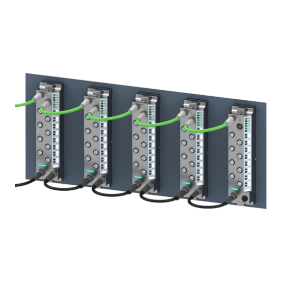
System overview What are the SIMATIC ET 200eco PN M12-L distributed I/O devices? SIMATIC ET 200eco PN M12‑L The SIMATIC ET 200eco PN M12‑L distributed I/O devices are part of a scalable and highly flexible, distributed I/O system for connecting the process signals to a higher-level controller via MultiFieldbus. - Page 35 System overview 5.1 What are the SIMATIC ET 200eco PN M12-L distributed I/O devices? Area of application The areas of application of the ET 200eco PN M12‑L are derived from its special properties: • A robust design and degrees of protection IP65/IP67 and IP69K make the ET 200eco PN M12‑L distributed I/O device suitable for use in harsh industrial...
-
Page 36: Components
System overview 5.2 Components Components Components of the ET 200eco PN M12‑L distributed I/O system The following table shows and explains the function of the most important components of the ET 200eco PN M12‑L distributed I/O system. Table 5-1 Overview of components Component Function Figure I/O device •... - Page 37 System overview 5.2 Components Component Function Figure Identification labels • The identification labels come with the module • They can be machine-printed • They can be ordered separately Sealing cap • Caps for unused connections • IP protection class is maintained through use PROFINET IO cable •...
- Page 38 System overview 5.2 Components Component Function Figure Y-connector • Double connection of actuators or sensors to one socket • IP protection class is maintained when 2 actuators or sensors are con nected to one socket Plug cover • For use in Zone 2 / Zone 22 hazard ous area Distributed I/O system ET 200eco PN M12-L System Manual, 11/2023, A5E48753295-AG...
-
Page 39: Mounting
Mounting Basics Introduction All ET 200eco PN M12‑L distributed I/O devices are designed for IP65/IP67 and IP69K degrees of protection. This means that you can directly mount these I/O devices in your plant. Only use such accessories which are permitted for the required degree of protection. Mounting position You can mount the ET 200eco PN M12‑L distributed I/O devices in any mounting position. -
Page 40: Mounting Without Mounting Rail
Mounting 6.2 Mounting without mounting rail Configuration variants There are two mounting variants: • Without mounting rail • With mounting rail You can find additional information in the following sections. Mounting without mounting rail Introduction The ET 200eco PN M12‑L distributed I/O devices are designed for installation on a level, firm surface. - Page 41 Mounting 6.2 Mounting without mounting rail Drill holes of the I/O device All enclosures of the ET 200eco PN M12‑L distributed I/O devices have a uniform hole pattern. The housings of the I/O devices are axially symmetric. The distance between the drill holes is identical for all I/O devices.
-
Page 42: Mounting With Mounting Rail
Mounting 6.3 Mounting with mounting rail Mounting with mounting rail Introduction A suitable mounting rail and profile screws are available as accessories for mounting the I/O devices. Advantages of the mounting rail: • Mounting rail can be cut to size for the application •... - Page 43 Mounting 6.3 Mounting with mounting rail Installing the mounting rail The mounting rail with 500 mm length must be cut to length according to your requirements. To install the mounting rail with 500 mm length, follow these steps: 1. Drill the mounting holes for screws with 8 mm diameter. We recommend that, after an initial distance of 12 mm, the mounting holes be provided at regular intervals of 182 mm.
-
Page 44: Installing The Plug Cover
Mounting 6.4 Installing the plug cover Installing the plug cover The plug cover is an accessory for protecting the connected connectors on the I/O device. The plug cover may be necessary for use in hazardous areas. Complete the following tasks before installing the plug cover: •... - Page 45 Mounting 6.4 Installing the plug cover Dimensions of plug cover The figure below shows the dimensions of the plug cover. Figure 6-5 Dimensions of plug cover Requirement The mounting of the I/O module is prepared according to the description of these sections: 1.
- Page 46 Mounting 6.4 Installing the plug cover Installing the plug cover For the installation, follow the steps below. 0,8...1Nm TX 10 Figure 6-6 Installing the plug cover 1. Loosen the mounting screws of the I/O device 2. Slide the plug cover part with the cable cutouts under the I/O device. 3.
-
Page 47: Connecting
Connecting Rules and regulations for operation Introduction The ET 200eco PN M12‑L distributed I/O devices are part of plants and systems. Depending on the area of application, follow the special rules and regulations. This section provides an overview of the most important rules to be followed for integrating the ET 200eco PN M12‑L distributed I/O devices into a plant or a system. - Page 48 In the event of danger through overvoltage, you must provide lightning protection measures for internal lightning protection (e.g. lightning protection elements). Additional information can be found in the function manual Designing interference-free controllers (https://support.industry.siemens.com/cs/ww/en/view/59193566). • For 24 V DC supply: Ensure that there is a safe electrical separation of extra-low voltage (SELV/PELV) according to IEC 61010-2-201 or IEC 60950-1.
-
Page 49: Operation On Grounded/Non-Grounded Infeed
– Line/wire break – Cross-circuit in the line Reference Additional information can be found in the function manual Designing interference-free con trollers (https://support.industry.siemens.com/cs/ww/en/view/59193566). Operation on grounded/non-grounded infeed Introduction Information is provided below on the overall configuration of an ET 200eco PN M12‑L distributed I/O system on a grounded incoming supply (TN-S network). The specific subjects discussed are: •... - Page 50 Connecting 7.2 Operation on grounded/non-grounded infeed Safe electrical isolation (SELV/PELV) Power packs/power supply modules with safe electrical isolation SELV/PELV are necessary for operating the ET 200eco PN M12‑L distributed I/O devices. These power supplies/power supply modules must comply with IEC 61010-2-201 or IEC 60950-1. The wiring of SELV/PELV circuits must be separated from the wiring of non-SELV/PELV circuits.
- Page 51 Connecting 7.2 Operation on grounded/non-grounded infeed Reference to IEC 60364 IEC 60204 illustration DIN VDE 0100 DIN VDE 0113 Short-circuit / over IEC 60364-5-55 IEC 60204-1 ② load protection VDE 0100 Part 557: VDE 0113 Part 1: • Grounded secondary circuit: • Grounded secondary circuit: Secure single pole Secure single pole •...
- Page 52 Connecting 7.2 Operation on grounded/non-grounded infeed Overall configuration of ET 200eco PN M12‑L The following figure shows a ET 200eco PN M12‑L distributed I/O device with electrical overall configuration. ① Main switch ② Short-circuit and overvoltage protection ③ Fuses for cable protection ④ When configuring the ET 200eco PN M12‑L distributed I/O devices with non-grounded refer ence potential, no connection is made between 1M, 2M and functional earth.
- Page 53 Connecting 7.2 Operation on grounded/non-grounded infeed Insulation monitoring In the following situations, you must provide insulation monitoring: • When setting up the ET 200eco PN M12‑L distributed I/O devices with non-grounded reference potential • If dangerous system states occur due to error Distributed I/O system ET 200eco PN M12-L System Manual, 11/2023, A5E48753295-AG...
-
Page 54: Electrical Configuration Of The Et 200Eco Pn M12-L
Connecting 7.3 Electrical configuration of the ET 200eco PN M12-L Electrical configuration of the ET 200eco PN M12-L Electrical isolation The electrical configuration of the ET 200eco PN M12‑L features electrical isolation between: • 1L+: Non-switched supply voltage (electronics/sensor/load supply): Isolated from MultiFieldbus and 2L+ (load voltage supply) •... - Page 55 Connecting 7.3 Electrical configuration of the ET 200eco PN M12-L Connection of a digital output with a digital input NOTICE Pay attention to the potential groups When a digital output is connected to a digital input, pay attention to the potential groups. Depending on the configuration, 1M and 2M can then be connected, resulting in elimination of the electrical isolation between 1L+ and 2L+.
-
Page 56: Connecting Et 200Eco Pn M12-L To The Functional Earth
Connecting 7.4 Connecting ET 200eco PN M12-L to the functional earth Reference You will find more information on electrical configuration and the voltage drop in the section Connecting cables for ET 200eco PN M12-L (Page 59). Connecting ET 200eco PN M12-L to the functional earth Introduction You must connect the ET 200eco PN M12‑L distributed I/O devices to the functional earth. -
Page 57: Mounting Et 200Eco Pn M12-L On Non-Conductive Surface
Connecting 7.4 Connecting ET 200eco PN M12-L to the functional earth Mounting Proceed as follows to connect ET 200eco PN M12‑L distributed I/O devices to functional earth with a conductive mounting surface: 1. Drill two fastening holes. The dimensions of the I/O device can be found in the section Dimension drawing (Page 113). - Page 58 Connecting 7.4 Connecting ET 200eco PN M12-L to the functional earth Mounting To connect ET 200eco PN M12‑L distributed I/O devices to functional earth, proceed as follows: 1. Drill two fastening holes. The dimensions of the I/O device can be found in the section Dimension drawing I/O device (Page 113).
-
Page 59: Connecting Cables For Et 200Eco Pn M12-L
Connecting 7.5 Connecting cables for ET 200eco PN M12-L Figure 7-4 Connecting the functional earth NOTE Earthing with non-conductive mounting substrate Make sure there is a low-impedance connection between the I/O device and the functional earth. Reference You will find more information on installing the I/O devices in the section Mounting (Page 39). -
Page 60: Wiring
Connecting 7.6 Wiring Derating of the input currents The table below shows the maximum permissible input current of the distributed I/O systems depending on the ambient temperature. Table 7-2 Deratings of the input currents while maintaining the minimum clearance Ambient temperature Max. - Page 61 Connecting 7.6 Wiring Accessories required when connecting the supply voltage You need the following accessories: • Pre-assembled power cable 4-pin M12-L coded • Flexible 4-wire copper cable (wire cross section: 1.5 to 2.5 mm ) and a connection plug 4-pin M12-L coded. Accessories required for the connection of MultiFieldbus You need the following accessories: •...
- Page 62 Connecting 7.6 Wiring The figure below shows the connection of the sensor/actuator M12 plugs. Figure 7-6 Connect sensor/actuator cable Pin assignment of the sockets The pin assignment of the sockets can be found in the manuals of the I/O device in the section on pin assignment.
- Page 63 Connecting 7.6 Wiring Y- connection The Y-connection allows you to connect two actuators or sensors to the inputs or outputs of the I/O devices. The use of a Y-cable or the Y-connector is particularly recommended when two channels are occupied for each socket of an I/O device. The Y-cable or the Y-connector distributes the two channels to two circular connectors.
-
Page 64: Marking The Et 200Eco Pn M12-L
Connecting 7.7 Marking the ET 200eco PN M12-L Marking the ET 200eco PN M12-L 7.7.1 Factory markings Introduction For better orientation, the ET 200eco PN M12‑L distributed I/O system is identified using various markings which will help you when configuring and connecting the I/O devices. Marking of the interfaces The interfaces of the I/O devices are factory-labeled. -
Page 65: Optional Markings
Connecting 7.7 Marking the ET 200eco PN M12-L 7.7.2 Optional markings Introduction In addition to the factory markings, there are also optional possibilities for labeling and/or identifying interfaces and I/O devices on the ET 200eco PN M12‑L distributed I/O system. Identification label The identification labels come with each I/O device as strips and can be machine-printed. A strip has 10 identification labels measuring 10 x 5 mm in the color RAL9016. -
Page 66: Mounting Identification Labels
Connecting 7.7 Marking the ET 200eco PN M12-L 7.7.3 Mounting identification labels Introduction This section describes how to mount or remove identification labels. Required tools You need a screwdriver with 3 mm blade width (only to remove identification labels). Mounting procedure To mount an identification label, proceed as follows: 1. -
Page 67: Configuring
• Comma Separated Values (CSV), contains the I/O data mapping of your configuration You can find additional information on MFCT in the "MultiFieldbus (https://support.industry.siemens.com/cs/ww/en/view/109773209)" function manual. Detect active fieldbus For exclusive operation on a fieldbus (not MF Shared Device) you can recognize the active fieldbus by the number of green LEDs on the MF Device. -
Page 68: Profinet Io
Information on the configuration can be obtained from the STEP 7 online help and in the SIMATIC PROFINET with STEP 7 (https://support.industry.siemens.com/cs/ww/en/view/49948856) system manual. Configuring the ET 200eco PN M12‑L with STEP 7 Classic The procedure for STEP 7 Classic can be found in the manual Programming with STEP 7 (https://support.industry.siemens.com/cs/ww/en/view/109751825). -
Page 69: Isochronous Real-Time Communication
Detailed information You can find additional information on the topic of isochronous real-time communication in the STEP 7 online help and in the SIMATIC PROFINET with STEP 7 (https://support.industry.siemens.com/cs/ww/en/view/49948856) function manual. Distributed I/O system ET 200eco PN M12-L System Manual, 11/2023, A5E48753295-AG... -
Page 70: Isochronous Mode
Detailed information You can find additional information on the topic of isochronous mode in the STEP 7 online help and in the SIMATIC PROFINET with STEP 7 (https://support.industry.siemens.com/cs/ww/en/view/49948856) function manual. Distributed I/O system ET 200eco PN M12-L System Manual, 11/2023, A5E48753295-AG... -
Page 71: Shared Device
Detailed information You can find additional information on the topic of shared device in the STEP 7 online help and in the SIMATIC PROFINET with STEP 7 (https://support.industry.siemens.com/cs/ww/en/view/49948856) function manual. 8.3.5 Module-internal shared input / shared output (MSI/MSO) Module-internal shared input / shared output (MSI/MSO) The module-internal shared input function allows an input module to make its input data available to several IO controllers. -
Page 72: System Redundancy S2
IO-Link connection can take more time, for example. You receive invalid values with value status QI = 0 until then. Detailed information You can find more information in the SIMATIC PROFINET with STEP 7 (https://support.industry.siemens.com/cs/ww/en/view/49948856) system manual. Distributed I/O system ET 200eco PN M12-L System Manual, 11/2023, A5E48753295-AG... -
Page 73: Device Replacement Without Programming Device
(STEP 7 V5.5 and higher). For additional information, refer to the STEP 7 online help and the SIMATIC PROFINET with STEP 7 (https://support.industry.siemens.com/cs/ww/en/view/49948856) manual. Distributed I/O system ET 200eco PN M12-L System Manual, 11/2023, A5E48753295-AG... -
Page 74: Ethernet/Ip
MultiFieldbus for all downstream devices. The bus interruption is evaluated by the software used and the controller. Detailed information You can find more information in the "MultiFieldbus (https://support.industry.siemens.com/cs/ww/en/view/109773209)" function manual. 8.4.2 EtherNet/IP functions The I/O modules can be configured with MFCT or another user program via EtherNet/IP. -
Page 75: Modbus Tcp
MultiFieldbus for all downstream devices. The bus interruption is evaluated by the software used and the controller. Detailed information You can find more information in the "MultiFieldbus (https://support.industry.siemens.com/cs/ww/en/view/109773209)" function manual. Distributed I/O system ET 200eco PN M12-L System Manual, 11/2023, A5E48753295-AG... -
Page 76: Modbus Tcp Functions
The module objects are displayed in the MFCT or in other software during the selection. Detailed information You can find more information in the MF Shared Device section of the "MultiFieldbus (https://support.industry.siemens.com/cs/ww/en/view/109773209)" function manual. Distributed I/O system ET 200eco PN M12-L System Manual, 11/2023, A5E48753295-AG... -
Page 77: Commissioning
Commissioning Commissioning ET 200eco PN M12-L on MultiFieldbus Introduction The commissioning of your distributed I/O devices depends on the respective plant configuration. The following procedure describes how to commission the ET 200eco PN M12‑L on an IO controller. Requirements for commissioning on the MultiFieldbus NOTE Performing tests You must ensure the safety of your plant. -
Page 78: Startup Of The I/O Device
Reference Additional information on the commissioning: • STEP 7 online help • In the manual SIMATIC PROFINET with STEP 7 (https://support.industry.siemens.com/cs/ww/en/view/49948856) • In the MultiFieldbus (https://support.industry.siemens.com/cs/ww/en/view/109773209) function manual Startup of the I/O device 9.2.1 Unconfigured without MultiFieldbus Startup without parameter assignment, without MultiFieldbus The following schematic diagram shows the startup of the ET 200eco PN M12-L in factory... -
Page 79: Unconfigured On Profinet Io
Commissioning 9.2 Startup of the I/O device 9.2.2 Unconfigured on PROFINET IO Startup without parameter assignment on PROFINET IO The following schematic diagram shows the startup of the ET 200eco PN M12-L in factory setting, without PROFINET IO: Distributed I/O system ET 200eco PN M12-L System Manual, 11/2023, A5E48753295-AG... -
Page 80: Configured On Profinet Io
Commissioning 9.2 Startup of the I/O device 9.2.3 Configured on PROFINET IO Startup configured on PROFINET IO The following schematic diagram shows the startup of the ET 200eco PN M12-L I/O device on PROFINET IO: Distributed I/O system ET 200eco PN M12-L System Manual, 11/2023, A5E48753295-AG... -
Page 81: Configured On Ethernet/Ip
Commissioning 9.2 Startup of the I/O device 9.2.4 Configured on EtherNet/IP Startup configured on EtherNet/IP The following schematic diagram shows the startup of the ET 200eco PN M12-L I/O device on EtherNet/IP: Distributed I/O system ET 200eco PN M12-L System Manual, 11/2023, A5E48753295-AG... -
Page 82: Configured On Modbus Tcp
Commissioning 9.2 Startup of the I/O device 9.2.5 Configured on Modbus TCP Startup configured on Modbus TCP The following schematic diagram shows the startup of the ET 200eco PN M12-L I/O device on Modbus TCP: Distributed I/O system ET 200eco PN M12-L System Manual, 11/2023, A5E48753295-AG... -
Page 83: Identification And Maintenance Data
With third party software, the "read record" instruction may be named differently. You can find more information in the "MultiFieldbus (https://support.industry.siemens.com/cs/ww/en/view/109773209)" function manual. Procedure for reading the I&M data using STEP 7 Requirement: An online connection to the I/O device must be available. -
Page 84: Data Record Structure For I&M Data
Commissioning 9.3 Identification and maintenance data Procedure for input of maintenance data using STEP 7 The default module name is assigned by STEP 7. You have the option to enter the following data: • Plant designation (I&M1) • Location identifier (I&M1) •... - Page 85 Explanation Identification data 0: (data record index AFF0 hex) VendorIDHigh read (1 byte) This is where the name of the manufac turer is stored (42 = SIEMENS AG). VendorIDLow read (1 byte) Order_ID read (20 bytes) 6ES7141-6BG00-0BB0 Order number of the I/O device (e.g. of the...
-
Page 86: Maintenance
Maintenance 10.1 Replacing an I/O device Replacing an I/O device Replacing an I/O device is not permitted during ongoing operation. NOTICE Material damage can occur If you connect or disconnect the I/O devices with the power connected, this can lead to undefined states in your system. - Page 87 Maintenance 10.1 Replacing an I/O device Procedure To replace an I/O device, follow these steps: 1. Disconnect the supply voltage to the I/O device to be replaced. 2. Completely remove all cables connected to the I/O device. 3. Loosen the fixing screws of the I/O device completely. 4.
-
Page 88: Firmware Update
3. The new I/O device and all downstream I/O devices start up again by themselves. Reference You will find information on the device name in the STEP 7 online help or the MultiFieldbus (https://support.industry.siemens.com/cs/ww/en/view/109773209) function manual. 10.2 Firmware update Introduction During operation, it may become necessary to update the firmware (e.g. -
Page 89: Calibrating An Analog I/O Device
After a firmware update, the I/O device remains in the bus protocol in which the update was installed. For example, at an update via EtherNet/IP, the I/O device remains in EtherNet/IP mode. Reference More information about the procedure: • FAQs on the Internet (http://www.siemens.com/automation/service&support) • STEP 7 online help • MultiFieldbus (https://support.industry.siemens.com/cs/ww/en/view/109773209) function manual 10.3... -
Page 90: Resetting The I/O Device To Factory Settings
Maintenance 10.4 Resetting the I/O device to factory settings Reference You can find information on the procedure in the Function Manual SIMATIC analog value pro cessing (https://support.industry.siemens.com/cs/ww/en/view/67989094). 10.4 Resetting the I/O device to factory settings Introduction When you "Reset to factory settings", the I/O device is reset to the "delivery state". All information that was saved internally on the I/O device is deleted. - Page 91 2 s while "Reset to factory settings" is running. Reference You will find more information on the procedure in the STEP 7 online help and in the Multi Fieldbus (https://support.industry.siemens.com/cs/ww/en/view/109773209) function manual. Distributed I/O system ET 200eco PN M12-L System Manual, 11/2023, A5E48753295-AG...
-
Page 92: Maintenance And Repair
Maintenance 10.6 Cleaning the I/O device 10.5 Maintenance and repair The components of the SIMATIC ET 200eco PN M12‑L system are maintenance-free. NOTE Repairs to an ET 200eco PN M12‑L I/O device may only be carried out by the manufacturer. 10.6 Cleaning the I/O device When wired, ET 200eco PN M12‑L I/O devices comply with the degrees of protection IP65/IP67 and IP69K. -
Page 93: Technical Specifications
You can find the associated certificates for download on the Internet. See also: ET 200eco PN approvals (https://support.industry.siemens.com/cs/ww/en/ps/14244/cert) CE marking The ET 200eco PN M12‑L distributed I/O devices meet the requirements and protection targets of the following directives. - Page 94 • Restriction of the Use of Certain Hazardous Substances in Electrical and Electronic Equipment Regulations 2012 (S.I. 2012 No. 3032), and related amendments UK Declarations of Conformity are available to the relevant authorities at the following address: Siemens AG Digital Industries Factory Automation DI FA TI COS TT...
- Page 95 More information You can find the explosion protection with the approved ET 200eco PN M12-L I/O devices here on the Internet (https://support.industry.siemens.com/cs/ww/en/ps/14244/cert?ct=441). The multilingual product information "Use of the ET 200eco PN M12-L in Zone 2/Zone 22 hazardous areas" is available here on the Internet (https://support.industry.siemens.com/cs/ww/en/view/109814099).
- Page 96 The multilingual product information "Use of the ET 200eco PN M12-L in Zone 2/Zone 22 hazardous areas" is available here on the Internet. See also Filter explosion protection certificates (https://support.industry.siemens.com/cs/ww/en/ps/14244/cert?ct=441) Use of the ET 200eco PN M12-L in Zone 2/Zone 22 hazardous areas(https://support.industry.siemens.com/cs/ww/en/view/109814099) Distributed I/O system ET 200eco PN M12-L...
- Page 97 More information You can find the explosion protection with the approved ET 200eco PN M12-L I/O devices here on the Internet (https://support.industry.siemens.com/cs/ww/en/ps/14244/cert?ct=441). The multilingual product information "Use of the ET 200eco PN M12-L in Zone 2/Zone 22 hazardous areas" is available here on the Internet (https://support.industry.siemens.com/cs/ww/en/view/109814099).
-
Page 98: Certificates
• RINA (Registro Italiano Navale) After a successful approval you can find the certificates with the certified article numbers in the Internet. See also: ET 200eco PN Marine/Shipbuilding (https://support.industry.siemens.com/cs/ww/en/ps/14244/cert?ct=446) Material compatibility test The distributed I/O devices ET 200eco PN M12‑L have been tested by the ECOLAB® company with the following liquids. -
Page 99: Standards And Requirements
Technical specifications 11.3 Standards and requirements 11.3 Standards and requirements IEC 61131-2 The ET 200eco PN M12‑L distributed I/O system fulfills the requirements and criteria of IEC 61131‑2 (Programmable controllers, Part 2: Equipment requirements and tests) and the EMC requirements for use in Zone B. IEC 61010-2-201 The ET 200eco PN M12‑L distributed I/O system fulfills the requirements and criteria of standard IEC 61010-2-201. -
Page 100: Electromagnetic Compatibility
Technical specifications 11.4 Electromagnetic compatibility Use in residential areas The ET 200eco PN M12‑L distributed I/O system is not intended for use in residential areas. Using the ET 200eco PN M12‑L distributed I/O system in residential areas can affect radio or television reception. 11.4 Electromagnetic compatibility Definition Electromagnetic compatibility is the ability of an electrical apparatus to function in a satisfactory manner in its electromagnetic environment without affecting this environment. - Page 101 Technical specifications 11.4 Electromagnetic compatibility Sinusoidal disturbance variables The following tables show the electromagnetic compatibility of the distributed I/O systems to sinusoidal disturbance variables. Table 11-2 RF radiation RF radiation according to IEC 61000-4-3 Corresponds Electromagnetic RF field, amplitude modulated with degree of severity 80 ... 1000 MHz 10 V/m...
-
Page 102: Transport And Storage Conditions
• The rated conditions exceed the requirements according to IEC 61131-2 – Class OTH2 You can find the values for the rated conditions in the technical specifications of the equipment manuals or on the Internet (https://support.industry.siemens.com/cs/de/en/view/109742718). Distributed I/O system ET 200eco PN M12-L System Manual, 11/2023, A5E48753295-AG... - Page 103 Technical specifications 11.6 Mechanical and climatic ambient conditions Tests of mechanical ambient conditions The following table shows the type and scope of the tests on mechanical ambient conditions. Table 11-7 Tests of mechanical ambient conditions Condition tested Test standard Values Sinusoidal vibrations, Vibration test accord...
- Page 104 Technical specifications 11.6 Mechanical and climatic ambient conditions Climatic ambient conditions The following table shows the type and scope of the tests on climatic ambient conditions. Table 11-9 Tests for climatic ambient conditions Ambient conditions Fields of application Comments Temperature -40 ... 60 °C All mounting positions* Temperature variation 10 K/h...
-
Page 105: Details On Insulation, Protection Class, Degree Of Protection And Rated Voltage
Technical specifications 11.7 Details on insulation, protection class, degree of protection and rated voltage 11.7 Details on insulation, protection class, degree of protection and rated voltage Insulation The insulation is designed in compliance with the requirements of IEC 61010-2-201. NOTE In the case of I/O devices with 24 V DC (SELV/PELV) supply voltage, galvanic isolations are tested with 707 V DC (type test). -
Page 106: Use Of The Et 200Eco Pn M12-L In Zone 2/Zone 22 Hazardous Areas
Zone 2/Zone 22 hazardous areas. The multilingual product information in different EU official languages is available here: Use of the ET 200eco PN M12-L in Zone 2/Zone 22 hazardous areas (https://support.industry.siemens.com/cs/ww/en/view/109814099) Approved I/O devices ET 200eco PN M12-L The I/O devices have these explosion approvals: •... - Page 107 Technical specifications 11.8 Use of the ET 200eco PN M12-L in Zone 2/Zone 22 hazardous areas Special conditions • Set up the I/O devices so that the risk of mechanical danger is low. • Adhere to the technical specifications for the I/O devices as specified in the EU -type examination certificate: –...
-
Page 108: Safety-Related Shutdown
Safety-related shutdown Safety-related shutdown of ET 200eco PN M12-L Introduction The setup below describes how you shut down ET 200eco PN M12-L standard modules in a fail-safe manner. With the illustrated setup (e.g. with safety relay 3SK1 or electronic module ET 200SP F-PM-E), all outputs that are connected to load voltage 2L+/2M (24 V switched) of the ET 200eco PN M12-L standard modules are switched to the safe OFF state. - Page 109 Figure A-1 Higher-level safety circuit of the outputs You can find an overview table with the article numbers of the I/O devices and other information in the FAQ on safety-related shutdown (https://support.industry.siemens.com/cs/ww/en/view/39198632). Distributed I/O system ET 200eco PN M12-L System Manual, 11/2023, A5E48753295-AG...
- Page 110 Figure A-2 Higher-level safety circuit of the outputs You can find an overview table with the article numbers of the I/O devices and other information in the FAQ on safety-related shutdown (https://support.industry.siemens.com/cs/ww/en/view/39198632). Planning Note the following points when planning safety circuits.
- Page 111 • Disabling of dark test (max. SIL 2, Cat.3/PL d) since it causes outputs to drop out briefly Observe the information in Manual for Power Module F-PM-E 24VDC/8A PPM ST (https://support.industry.siemens.com/cs/ww/en/view/78645796) and Product information for Power Module F-PM-E 24VDC/8A PPM ST (https://support.industry.siemens.com/cs/ww/en/view/109761777) •...
- Page 112 This FAQ specifies the SIMATIC standard modules that are suitable for a safety-related shutdown and a file with wiring examples. Request TÜV report (Report no. SN96753T) You can request copies of the TÜV report at the following address: SIEMENS AG Digital Industries DI FA TI COS TT P.O. Box 1963...
-
Page 113: Dimension Drawings
Dimension drawings Dimension drawing I/O device The following figure shows the dimensions of an I/O device of the distributed I/O system ET 200eco PN M12-L. Figure B-1 Dimension drawing of an I/O device Distributed I/O system ET 200eco PN M12-L System Manual, 11/2023, A5E48753295-AG... -
Page 114: Dimension Drawing Of Plug Cover
Dimension drawings B.2 Dimension drawing of plug cover Dimension drawing of plug cover The figure below shows the dimensions of the plug cover for a distributed I/O device ET 200eco PN M12-L. Figure B-2 Dimension drawing of plug cover Distributed I/O system ET 200eco PN M12-L System Manual, 11/2023, A5E48753295-AG... -
Page 115: Accessories/Spare Parts
Accessories/spare parts Accessories/spare parts Accessories for the ET 200eco PN M12-L distributed I/O system Table C-1 Accessories for power supply Designation Length Article number Cable is pre-assembled CONNECTING CABLE M12, L-CODED 0.5 m 6XV1801-6DE50 Power connecting cable M12-180/M12-180 for power 1.0 m 6XV1801-6DH10 supply of ET 200 1.5 m 6XV1801-6DH15 Pre-assembled cable with M12 plug and M12 socket,... - Page 116 Accessories/spare parts C.1 Accessories/spare parts Designation Article number PROFINET M12 connector, D-coded with FastConnect 1 unit/ 6GK1901‑0DB20‑6AA0 connection system, 180° pack 8 units/ 6GK1901‑0DB20‑6AA8 pack PROFINET M12 connector, D-coded, angled 3RK1902‑2DA00 Table C-3 Non-preassembled cable PROFINET (sold by the meter) Designation Article number Non-preassembled connectors for X1 P1R PN (LAN) and X1 P2R PN (LAN) PROFINET FC cable FC TP Standard Cable...
- Page 117 Accessories/spare parts C.1 Accessories/spare parts Designation Article number PROFINET M12 connecting cable, trailing cable, pre- 3.0 m 3RK1902‑2HB30 assembled on one side with M12 plug, angled (one end 5.0 m 3RK1902‑2HB50 with pin, one end open) 10.0 m 3RK1902‑2HC10 PROFINET M12 connecting cable, trailing cable, pre- 2.0 m 6XV1871‑5TH20 assembled on one side with M12 plug 180°...
-
Page 118: Ul-Approved Cables
7021, straight socket M12, coding: L, free cable end UL-approved cables from Siemens In combination with the cables listed for the connection of DI/DQ of the manufacturer Siemens, the SIMATIC ET 200eco PN M12‑L distributed I/O devices meet the UL approval. Table C-8 Accessories for DI/DQ connection Designation... -
Page 119: Plug Cover For Et 200Ecopn M12-L
Accessories/spare parts C.3 Plug cover for ET 200ecoPN M12-L Designation Length Article number Power connecting cable M12-180/M12-180 for power supply of ET 200, 1.5 m 6XV1801-5DH15 pre-assembled cable with M12 connector and M12 socket, a-coded, 2.0 m 6XV1801-5DH20 5-pin 3.0 m 6XV1801-5DH30 5.0 m 6XV1801-5DH50 10.0 m 6XV1801-5DN10 15.0 m 6XV1801-5DN15... - Page 120 Accessories/spare parts C.3 Plug cover for ET 200ecoPN M12-L Article number 6ES7194-6JA00-0BB0 Mechanics/material Material of housing stainless steel with plastic edge protection Material property • Silicone-free Dimensions Width 50 mm Height 200 mm Depth 110 mm Weights Weight, approx. 710 g Distributed I/O system ET 200eco PN M12-L System Manual, 11/2023, A5E48753295-AG...
-
Page 121: Glossary
Glossary A common transfer route connecting all nodes and having two defined ends. Configuration Systematic arrangement of the individual I/O devices (configuration). Connection plug Physical connection between device and cable. Derating Derating allows devices to be used even in harsh operating conditions by selectively restricting the output capacity. - Page 122 Glossary Functional grounding Functional grounding is a low-impedance current path between electric circuits and ground. It is not designed as a safety measure but instead, for example, as a measure to improve interference immunity. Functional status (FS) Functional status provides information on the hardware version of the module. Ground Conductive ground whose electrical potential can be set equal to zero at any point.
- Page 123 Glossary Modbus TCP Modbus protocol as a communication protocol which is based on a master/device or client/server architecture and permits Ethernet TCP/IP as a further transmission technology MultiFieldbus MultiFieldbus states that a device supports several bus protocols. For example, PROFINET, Modbus TCP and EtherNet/IP. Parameter assignment Parameter assignment is the transfer of parameters from the IO controller to the IO device.
- Page 124 Glossary TIA Portal Totally Integrated Automation Portal TIA Portal is the key to the full performance capability of Totally Integrated Automation. The software optimizes operating, machine and process sequences. Value status Binary additional information for an input signal. This additional information indicates whether or not the input signal is valid.
-
Page 125: Index
Index Commissioning ET 200eco PN M12‑L, 77 24 V DC supply, 48 Configuration, 35 Power supply, 55 Functional earth, 56 Configuration example, 35 Accessories, 115 Connecting Ambient conditions Conductive substrate, 57 Mechanical, 103 Non-conductive substrate, 58 Climatic, 104 M12 plugs, 61 Application, 47 Connecting cables, 59 Burst pulses, 100 Degree of protection, 105 Derating, 39... - Page 126 Index Functional earth, 56 Mounting position, 39 Fuse, 48 MSI, 71 MSO, 71 MultiFieldbus Behavior, 86 Grounded infeed, 49 Outdoors, 103 Hazardous area Overall configuration, 52 Special conditions, 107 Overvoltage category, 105 Identification data, 83 Identification label, 65 PELV, 50, 50 Mounting, 66 Plug cover, 44 Removing, 66...
- Page 127 Index Shock, 103 SIMATIC ET 200eco PN M12‑L, 34 Sinusoidal disturbance variables, 101 Sockets, 63 Spare parts, 115 Standards IEC 61131-2, 99 IEC 61010-2-201, 99 PROFINET standard, IEC 61158 Type 10, 99 EtherNet/IP requirement, 99 Modbus TCP requirement, 99 IO-Link standard, IEC 61131-9, 99 Use in industrial environments, 99 Use in mixed areas, 99 Use in residential areas, 100 Switch, 48...
Need help?
Do you have a question about the SIMATIC ET 200eco PN M12-L and is the answer not in the manual?
Questions and answers