Siemens SIMATIC ET 200eco PN M12-L Equipment Manual
Hide thumbs
Also See for SIMATIC ET 200eco PN M12-L:
- Operating instructions manual (278 pages) ,
- Compact operating instructions (156 pages) ,
- System manual (127 pages)

Related Manuals for Siemens SIMATIC ET 200eco PN M12-L


Summary of Contents for Siemens SIMATIC ET 200eco PN M12-L
- Page 1 Edition 03/2023 Equipment Manual SIMATIC ET 200eco PN M12-L I/O device digital outputs DQ 8x24VDC/0.5A M12-L 8xM12 (6ES7142-6BG00-0BB0) support.industry.siemens.com...
- Page 2 Guide to ET 200eco PN M12-L Product overview SIMATIC Wiring ET 200eco PN I/O device digital outputs PROFINET IO DQ 8x24VDC/0.5A M12-L 8xM12 (6ES7142-6BG00-0BB0) EtherNet/IP Equipment Manual Modbus TCP Technical specifications Dimension drawing Parameter data record 03/2023 A5E46570894-AD...
- Page 3 Note the following: WARNING Siemens products may only be used for the applications described in the catalog and in the relevant technical documentation. If products and components from other manufacturers are used, these must be recommended or approved by Siemens. Proper transport, storage, installation, assembly, commissioning, operation and maintenance are required to ensure that the products operate safely and without any problems.
- Page 4 Preface Purpose of the documentation This equipment manual supplements the ET 200eco PN M12-L Distributed I/O System (https://support.industry.siemens.com/cs/ww/en/view/109778292) system manual. Functions that relate in general to the distributed I/O devices ET 200eco PN M12‑L are described in this system manual. The MultiFieldbus (https://support.industry.siemens.com/cs/ww/en/view/109773209) Function Manual describes general MultiFieldbus functions. This equipment manual describes the specific adaptations for this I/O device.
- Page 5 Siemens' products and solutions undergo continuous development to make them more secure. Siemens strongly recommends that product updates are applied as soon as they are available and that the latest product versions are used. Use of product versions that are no longer supported, and failure to apply the latest updates may increase customers' exposure to cyber threats.
-
Page 6: Table Of Contents
Table of contents Guide to ET 200eco PN M12-L......................Information classes ET 200eco PN M12-L................Basic tools........................MultiFieldbus Configuration Tool (MFCT)................SIMATIC Technical Documentation..................12 Product overview..........................14 Properties ........................14 Operator controls and display elements................16 Wiring..............................17 Terminal and block diagram....................17 Pin assignment......................... - Page 7 Table of contents Modbus TCP............................45 Functions/parameters/address space................. 45 6.1.1 Supported Modbus TCP functions..................45 6.1.2 Parameters........................46 6.1.3 Explanation of the parameters..................46 6.1.4 Update time of the I/O data....................47 6.1.5 Address space........................47 Diagnostics........................52 6.2.1 Status and error displays for Modbus TCP................52 Technical specifications........................
-
Page 8: Guide To Et 200Eco Pn M12-L
This arrangement enables you to access the specific content you require. You can download the documentation free of charge from the Internet (https://support.industry.siemens.com/cs/de/en/view/109742718). Basic information The System Manual describes in detail the configuration, installation, wiring and commissioning of the SIMATIC ET 200eco PN M12-L distributed I/O system. -
Page 9: Basic Tools
With the TIA Selection Tool , you can generate a complete order list from your product selection or product configuration. You can find the TIA Selection Tool on the Internet. (https://support.industry.siemens.com/cs/ww/en/view/109767888) SIMATIC Automation Tool You can use the SIMATIC Automation Tool to perform commissioning and maintenance activities on various SIMATIC S7 stations as bulk operations independent of TIA Portal. - Page 10 You can find SIEMENS PRONETA Basic on the Internet: (https://support.industry.siemens.com/cs/ww/en/view/67460624) SIEMENS PRONETA Professional is a licensed product that offers you additional functions. It offers you simple asset management in PROFINET networks and supports operators of automation systems in automatic data collection/acquisition of the components used through various functions: •...
-
Page 11: Multifieldbus Configuration Tool (Mfct)
MultiFieldbus- and DALI-devices. In addition, the MFCT offers convenient options for mass firmware updates of ET 200 devices with MultiFieldbus- support and reading service data for many other Siemens devices. Functional scope of the MFCT • MultiFieldbus configuration:... -
Page 12: Simatic Technical Documentation
Online Support: Industry Online Support International https://support.industry.siemens.com/cs/ww/en/view/109742705 Watch this short video to find out where you can find the overview directly in Siemens Industry Online Support and how to use Siemens Industry Online Support on your mobile device: Quick introduction to the technical documentation of automation products per video ( https://support.industry.siemens.com/cs/us/en/view/109780491... - Page 13 Solutions are shown in interplay with multiple components in the system - separated from the focus on individual products. You can find the application examples on the Internet. (https://support.industry.siemens.com/cs/ww/en/ps/ae) I/O device digital outputs DQ 8x24VDC/0.5A M12-L 8xM12 (6ES7142-6BG00-0BB0) Equipment Manual, 03/2023, A5E46570894-AD...
-
Page 14: Product Overview
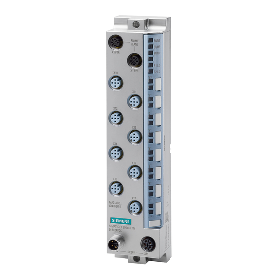
Product overview Properties Article number 6ES7142-6BG00-0BB0 View of the I/O device Figure 2-1 View of the I/O device DQ 8x24VDC/0.5A M12-L 8xM12 I/O device digital outputs DQ 8x24VDC/0.5A M12-L 8xM12 (6ES7142-6BG00-0BB0) Equipment Manual, 03/2023, A5E46570894-AD... - Page 15 Product overview 2.1 Properties Properties The I/O device has the following technical properties: • Using the MultiFieldbus function, it connects the ET 200eco PN M12‑L distributed I/O system with one of the following bus protocols: – PROFINET IO – EtherNet/IP – Modbus TCP • 8 digital outputs •...
-
Page 16: Operator Controls And Display Elements
2.2 Operator controls and display elements See also You can find additional information on the accessories in the ET 200eco PN M12-L distributed I/O system (https://support.industry.siemens.com/cs/ww/en/view/109778292) system manual. Operator controls and display elements The figure below shows the operator controls and display elements of the DQ 8x24VDC/0.5A M12‑L 8xM12 I/O device. -
Page 17: Wiring
Wiring Terminal and block diagram The figure below shows an example of the connections and components of the I/O device. I/O device digital outputs DQ 8x24VDC/0.5A M12-L 8xM12 (6ES7142-6BG00-0BB0) Equipment Manual, 03/2023, A5E46570894-AD... - Page 18 Wiring 3.1 Terminal and block diagram ① Bus interface with integrated X1 P1R MultiFieldbus interface X1 RN/NS RUN/network status LED 2-port switch Port 1 ② Monitoring X1 P2R MultiFieldbus interface X1 ER/MS ERROR/module status LED Port 2 ③ DQ circuit Supply voltage 1L+ (non- MT/IO MAINT/IO status LED switched)
-
Page 19: Pin Assignment
Wiring 3.2 Pin assignment ① Output (dual assignment of Supply voltage 1L+ (non- Load voltage 2L+ (switched) the socket) switched) ② Output (single assignment of Ground 1M (non-switched) Ground 2M (switched) socket) ③ Output (single assignment of Output signal socket) Figure 3-2 Terminal circuit diagram Pin assignment Pin assignment MultiFieldbus connector... - Page 20 Wiring 3.2 Pin assignment Pin assignment of sockets for digital outputs The table below shows the pin assignment of the 8 sockets for the connection of the digital outputs. Table 3-2 Pin assignment for digital outputs Assignment Front view of the sockets X10 to X17 - sockets for digital outputs X10, X12, X11, X13,...
- Page 21 Wiring 3.2 Pin assignment The following graphic shows the assignment of the output signals to the respective sockets with dual or single assignment. Figure 3-3 Assignment of output signals with dual or single assignment of sockets Pin assignment of the connector for infeed of the supply voltage (M12 L-coded) The table below shows the pin assignment of the M12 L-coded connector for infeed of the supply voltage.
- Page 22 Wiring 3.2 Pin assignment Pin assignment of the socket for loop-through of the supply voltage (M12 L-coded) The table below shows the pin assignment of the M12 L-coded socket for loop-through of the supply voltage. Table 3-4 Pin assignment of the supply voltage socket Assignment of the Assignment Front view of the sock...
-
Page 23: Profinet Io
PROFINET IO Parameters/address space 4.1.1 Parameters The table below shows the parameters for the I/O device DQ 8x24VDC/0.5A M12‑L 8xM12. Table 4-1 Configurable parameters and their defaults (GSD file) Parameters Value range Default Scope with configura tion software, e.g. STEP 7 (TIA Portal) Diagnostics: Low voltage 1L+ •... -
Page 24: Explanation Of The Parameters
PROFINET IO 4.1 Parameters/address space 4.1.2 Explanation of the parameters Diagnostics: Low voltage 1L+ Enabling of the diagnostics for insufficient supply voltage 1L+. Diagnostics: Low voltage 1L+ triggers the "Undervoltage" maintenance event. You can find more information in section Maintenance events (Page 32). Diagnostics: Missing 2L+ Enabling of the diagnostics for missing or insufficient load voltage 2L+. -
Page 25: Address Space
PROFINET IO 4.1 Parameters/address space 4.1.3 Address space The DQ 8x24VDC/0.5A M12-L 8xM12 I/O device can be configured differently; see following table. Depending on the configuration, additional/different addresses are assigned in the process images. Configuration options of the DQ 8x24VDC/0.5A M12-L 8xM12 I/O device You can configure the I/O device Digital Outputs as follows: •... - Page 26 PROFINET IO 4.1 Parameters/address space Value status (Quality Information, QI) The value status is always returned with the following configuration options: • DQ 8x24VDC QI • DQ 8x24VDC MSO Evaluating the value status An additional byte is occupied in the input address space if you enable the value status for the I/O device.
- Page 27 You can find information on the functionality Module-internal Shared Input/Shared Output (MSI/MSO) in the STEP 7 online help or in the function manual SIMATIC PROFINET with STEP 7 (https://support.industry.siemens.com/cs/ww/en/view/49948856). Address space for configuration as 2 x 4-channel DQ 8x24VDC S The figure below shows the address space assignment for configuration as a 2 x 4-channel I/O device digital outputs.
-
Page 28: Interrupts/Diagnostics Alarms
PROFINET IO 4.2 Interrupts/diagnostics alarms Interrupts/diagnostics alarms 4.2.1 Status and error displays LED displays The figure below shows the LED displays (status and error displays) of the I/O device DQ 8x24VDC/0.5A M12-L 8xM12. PN/MF RN/NS (LAN) ER/MS MT/IO X1 P1R P1 LK X1 P2R P2 LK MAC-ADD.;... - Page 29 PROFINET IO 4.2 Interrupts/diagnostics alarms Behavior of the LEDs RN/NS (RUN/network status), ER/MS (ERROR/module status) and MT/IO (MAINT/IO status) on PROFINET Table 4-3 Fault display of the LEDs LEDs Meaning Solution Missing or insufficient supply voltage Check the supply voltage. at the I/O device. Test of LEDs during startup: The three LEDs light up simultaneously for approximately 0.25 s.
- Page 30 PROFINET IO 4.2 Interrupts/diagnostics alarms PWR LED Table 4-4 Status display of the PWR LED PWR LED Meaning Load voltage 2L+ is missing or too low Load voltage 2L+ present P1 LK and P2 LK LEDs Table 4-5 Error display of the P1 LK and P2 LK LEDs LEDs Meaning Solution...
-
Page 31: Interrupts
PROFINET IO 4.2 Interrupts/diagnostics alarms 4.2.2 Interrupts The I/O device digital outputs DQ 8x24VDC/0.5A M12‑L 8xM12 supports diagnostic interrupts and maintenance alarms. Diagnostic interrupt The I/O device generates a diagnostic interrupt on the following events: • Wire break • Internal module fault •... -
Page 32: Maintenance Events
PROFINET IO 4.2 Interrupts/diagnostics alarms Diagnostics alarm Error code Meaning Corrective measures Wire break Channel not connected (open) • Disable diagnostics • Connect a resistor to the actuator con tacts in the load resistance range. Error Internal module error has occurred Replace the I/O device. -
Page 33: Ethernet/Ip
EtherNet/IP Functions/parameters/address space 5.1.1 Supported EtherNet/IP functions Supported functions The table below shows the functions that the I/O device supports with EtherNet/IP. Supported functions Remarks I/O communication with scanner FW 5.1.x or higher Parameter assignment FW 5.1.x or higher Reading diagnostics FW 5.1.x or higher Normative CIP objects FW 5.1.x or higher... -
Page 34: Parameters
EtherNet/IP 5.1 Functions/parameters/address space Supported CIP objects for EtherNet/IP The table below shows the CIP objects that the I/O device supports with EtherNet/IP. Supported CIP objects Remarks Identity object FW 5.1.x or higher Assembly object FW 5.1.x or higher Connection Manager object FW 5.1.x or higher TCP/IP Interface object FW 5.1.x or higher... -
Page 35: Explanation Of The Parameters
EtherNet/IP 5.1 Functions/parameters/address space 5.1.3 Explanation of the parameters Diagnostics: Low voltage 1L+ Enabling of the diagnostics for insufficient supply voltage 1L+. Diagnostics: Missing 2L+ Enabling of the diagnostics for missing or insufficient load voltage 2L+. Diagnostics: Short-circuit Enabling of the diagnostics for short-circuit of the output to ground. Diagnostics: Wire break Enabling of diagnostics when the line between the actuator and the I/O device is interrupted. -
Page 36: Address Space
EtherNet/IP 5.1 Functions/parameters/address space 5.1.5 Address space The DQ 8x24VDC/0.5A M12-L 8xM12 I/O device can be configured differently; see following table. Depending on the configuration, additional/different addresses are assigned in the process images. Configuration options of the DQ 8x24VDC/0.5A M12-L 8xM12 I/O device When the I/O device is configured using a GSD file, the configurations are available under different short designations/device names in the device view of MFCT. - Page 37 EtherNet/IP 5.1 Functions/parameters/address space Value status (Quality Information, QI) The value status is always returned with the following configuration options: • DQ 8x24VDC QI • DQ 8x24VDC MSO Evaluating the value status An additional byte is occupied in the input address space if you enable the value status for the I/O device.
- Page 38 EtherNet/IP 5.1 Functions/parameters/address space Address space for configuration as 1 x 8-channel DQ 8x24VDC MSO With the configuration 1 x 8-channel I/O device (module-internal shared output, MSO), the channels 0 to 7 (incl. value status) of the I/O device are copied into two submodules. Channels 0 to 7 are then available with identical values in various submodules.
- Page 39 Figure 5-3 Address space for configuration as 1 x 8-channel DQ 8x24VDC MSO with value status Reference You can find information about the Module Internal Shared Input/Shared Output (MSI/MSO) functionality in the MultiFieldbus (https://support.industry.siemens.com/cs/ww/en/view/109773209) Function Manual SIMATIC PROFINET with STEP 7 (https://support.industry.siemens.com/cs/ww/en/view/49948856). I/O device digital outputs DQ 8x24VDC/0.5A M12-L 8xM12 (6ES7142-6BG00-0BB0) Equipment Manual, 03/2023, A5E46570894-AD...
- Page 40 EtherNet/IP 5.1 Functions/parameters/address space Address space for configuration as 2 x 4-channel DQ 8x24VDC S The figure below shows the address space assignment for configuration as a 2 x 4-channel I/O device digital outputs. Figure 5-4 Address space for configuration as 2 x 4-channel DQ 8x24VDC S I/O device digital outputs DQ 8x24VDC/0.5A M12-L 8xM12 (6ES7142-6BG00-0BB0) Equipment Manual, 03/2023, A5E46570894-AD...
-
Page 41: Diagnostics
EtherNet/IP 5.2 Diagnostics Diagnostics 5.2.1 Status and error displays for EtherNet/IP LED displays The figure below shows the LED displays (status and fault displays) of the I/O device DQ 8x24VDC/0.5A M12-L 8xM12. PN/MF RN/NS (LAN) ER/MS MT/IO X1 P1R P1 LK X1 P2R P2 LK MAC-ADD.;... - Page 42 EtherNet/IP 5.2 Diagnostics Behavior of the LEDs RN/NS (RUN/network status), ER/MS (ERROR/module status) and MT/IO (MAINT/IO status) on EtherNet/IP The LEDs display the status with the highest priority if there are different LED states due to overlaid events. (0 = off, 1 = green flashing, 2 = green, 3 = yellow, 4 = red flashing, 5 = red) The following table shows the meaning of the RN/NS, ER/MS LEDs and MT/IO LEDs for EtherNet/IP: Table 5-3 Error display of the LEDs...
- Page 43 EtherNet/IP 5.2 Diagnostics LEDs Meaning Remedy Test of LEDs during startup: The three LEDs light up simultaneously for Flashes Flashes Flashes approximately 0.25 s in red. Then for approximately 0.25 s in green. Hardware or firmware defective. You can read out the service data with MFCT.
- Page 44 EtherNet/IP 5.2 Diagnostics Channel status/channel fault LED Table 5-6 Status and fault display of the channel status/channel fault LED LEDs Meaning Channel status/channel fault Process value = 0 Process value = 1 Channel diagnostics I/O device digital outputs DQ 8x24VDC/0.5A M12-L 8xM12 (6ES7142-6BG00-0BB0) Equipment Manual, 03/2023, A5E46570894-AD...
-
Page 45: Modbus Tcp
Modbus TCP Functions/parameters/address space 6.1.1 Supported Modbus TCP functions Supported functions The table below shows the functions that the I/O device supports with Modbus TCP. Supported functions RegLayoutVersion Remarks I/O communication with Modbus client V1.0 FW 5.1.x or higher Free user registers (e.g. for coordination of the redundancy) V1.0 FW 5.1.x or higher Device information... -
Page 46: Parameters
Modbus TCP 6.1 Functions/parameters/address space 6.1.2 Parameters The table below shows the parameters for the I/O device DQ 8x24VDC/0.5A M12‑L 8xM12. Table 6-1 Configurable parameters and their defaults (GSD file) Parameters Value range Default Effective range with configuration soft ware, for example, MFCT Diagnostics: Low voltage 1L+ •... -
Page 47: Update Time Of The I/O Data
Modbus TCP 6.1 Functions/parameters/address space Reaction to CPU STOP With this parameter, you set the reaction of the digital outputs of the I/O device after a CPU STOP: • Shutdown: The digital output is de-energized. • Keep last value: The last value of the digital output remains activated. •... - Page 48 Modbus TCP 6.1 Functions/parameters/address space Address space for configuration as 1 x 8-channel DQ 8x24VDC The following figure shows the address space allocation for the configuration as 8-channel I/O device digital outputs without value status. The addresses of the channels are derived from the start address.
- Page 49 Modbus TCP 6.1 Functions/parameters/address space Address space for configuration as 1 x 8-channel DQ 8x24VDC QI The following figure shows the address space allocation for the configuration as 8-channel I/O device digital outputs with value status. Figure 6-2 Address space for configuration as 1 x 8-channel DQ 8x24VDC QI with value status Address space for configuration as 1 x 8-channel DQ 8x24VDC MSO With the configuration 1 x 8-channel I/O device (module-internal shared output, MSO), the channels 0 to 7 (incl.
- Page 50 Figure 6-3 Address space for configuration as 1 x 8-channel DQ 8x24VDC MSO with value status Reference You can find information about the Module Internal Shared Input/Shared Output (MSI/MSO) functionality in the MultiFieldbus (https://support.industry.siemens.com/cs/ww/en/view/109773209) Function Manual SIMATIC PROFINET with STEP 7 (https://support.industry.siemens.com/cs/ww/en/view/49948856). I/O device digital outputs DQ 8x24VDC/0.5A M12-L 8xM12 (6ES7142-6BG00-0BB0) Equipment Manual, 03/2023, A5E46570894-AD...
- Page 51 Modbus TCP 6.1 Functions/parameters/address space Address space for configuration as 2 x 4-channel DQ 8x24VDC S The figure below shows the address space assignment for configuration as a 2 x 4-channel I/O device digital outputs. Figure 6-4 Address space for configuration as 2 x 4-channel DQ 8x24VDC S I/O device digital outputs DQ 8x24VDC/0.5A M12-L 8xM12 (6ES7142-6BG00-0BB0) Equipment Manual, 03/2023, A5E46570894-AD...
-
Page 52: Diagnostics
Modbus TCP 6.2 Diagnostics Diagnostics 6.2.1 Status and error displays for Modbus TCP LED displays The figure below shows the LED displays (status and fault displays) of the I/O device DQ 8x24VDC/0.5A M12-L 8xM12. PN/MF RN/NS (LAN) ER/MS MT/IO X1 P1R P1 LK X1 P2R P2 LK... - Page 53 Modbus TCP 6.2 Diagnostics Behavior of the LEDs RN/NS (RUN/network status), ER/MS (ERROR/module status) and MT/IO (MAINT/IO status) on modbus TCP The LEDs display the status with the highest priority if there are different LED states due to overlaid events. (0 = off, 1 = green flashing, 2 = green, 3 = yellow, 4 = red flashing, 5 = red) The following table shows the meaning of the RN/NS, ER/MS LEDs and MT/IO LEDs for Modbus TCP: Table 6-3 Error display of the LEDs...
- Page 54 Modbus TCP 6.2 Diagnostics PWR LED Table 6-4 Status display of the PWR LED PWR LED Meaning Load voltage 2L+ is missing or too low Load voltage 2L+ present P1 LK and P2 LK LEDs Table 6-5 Error display of the P1 LK and P2 LK LEDs LEDs Meaning Remedy...
-
Page 55: Technical Specifications
Technical specifications Technical specifications of the I/O device DQ 8x24VDC/0.5A M12-L 8xM12 The following table shows the technical specifications as of the issue date. You can find a data sheet including daily updated technical specifications on the Internet (https://support.industry.siemens.com/cs/de/en/pv/6ES7142-6BG00-0BB0/td?dl=en). Article number 6ES7142-6BG00-0BB0 General information ... - Page 56 Technical specifications Article number 6ES7142-6BG00-0BB0 Load voltage 2L+ • Rated value (DC) 24 V permissible range, lower limit (DC) 20.4 V • • permissible range, upper limit (DC) 28.8 V • Reverse polarity protection Yes; against destruction; load increasing Input current Current consumption (rated value) 65 mA;...
- Page 57 Technical specifications Article number 6ES7142-6BG00-0BB0 Output delay with resistive load • "0" to "1", max. 50 µs; at rated load "1" to "0", max. 100 µs; at rated load • Parallel switching of two outputs • for uprating • for redundant control of a load Switching frequency ...
- Page 58 Technical specifications Article number 6ES7142-6BG00-0BB0 PROFINET IO Device Services – Yes; 250 µs to 4 ms in 125 µs frame Prioritized startup – – Shared device – Number of IO Controllers with shared device, max. Redundancy mode •...
- Page 59 Technical specifications Article number 6ES7142-6BG00-0BB0 Modbus TCP Services – read coils (code=1) read discrete inputs (code=2) – – Read Holding Registers (Code=3) – write single coil (code=5) – write multiple coils (code=15) – Write Multiple Registers (Code=16) Parameter change by master –...
- Page 60 PL d 13849-1 Category according to ISO 13849-1 Cat. 3 • • SIL acc. to IEC 62061 SIL 2 remark on safety-oriented shutdown https://sup • port.industry.siemens.com/cs/de/en/view/39198 Ambient conditions Ambient temperature during operation min. -40 °C • • max. 60 °C I/O device digital outputs DQ 8x24VDC/0.5A M12-L 8xM12 (6ES7142-6BG00-0BB0)
- Page 61 Technical specifications Article number 6ES7142-6BG00-0BB0 Altitude during operation relating to sea level • Ambient air temperature-barometric pres Up to max. 5 000 m, at installation height > 2 sure-altitude 000 m additional restrictions connection method / header Design of electrical connection 4/5-pin M12 circular connectors Design of electrical connection for the inputs M12, 5-pin, A-coded...
-
Page 62: A Dimension Drawing
Dimension drawing Dimension drawing The figure below shows the dimension drawing of the I/O device digital outputs DQ 8x24VDC/0.5A M12‑L 8xM12 in front and side views. Figure A-1 Dimension drawing I/O device digital outputs DQ 8x24VDC/0.5A M12-L 8xM12 (6ES7142-6BG00-0BB0) Equipment Manual, 03/2023, A5E46570894-AD... -
Page 63: Parameter Data Record
Parameter data record Dependencies for the configuration When configuring the I/O device, the parameter settings are independent of each other. Structure of data record 128 for I/O device parameter assignment With data record 128, you can reconfigure the I/O device in your user program, regardless of your programming. - Page 64 Parameter data record B.2 Structure of data record 128 for I/O device parameter assignment Structure of data record 128 The figure below shows the structure of data record 128. On the left, you can see the structure of data record 128 when it is configured as an 1 x 8-channel I/O device.
- Page 65 Parameter data record B.2 Structure of data record 128 for I/O device parameter assignment Device header information The figure below shows the structure of the device header information. Figure B-3 Device header information Device parameter block The figure below shows the structure of the device parameter block. Figure B-4 Device parameter block Channel header information The figure below shows the structure of the channel header information.
- Page 66 Parameter data record B.2 Structure of data record 128 for I/O device parameter assignment Parameters The following figure shows the structure of the parameters for a channel. You activate a parameter by setting the corresponding bit to "1". The channel number depends on the parameter assignment of the I/O device. •...
-
Page 67: Error Transferring The Data Record
Parameter data record B.3 Error transferring the data record Error transferring the data record Error transferring the data record The I/O device checks the values of the transferred data record. Only if the values were transferred without errors does the I/O device apply the values from the data record. The "WRREC"...
Need help?
Do you have a question about the SIMATIC ET 200eco PN M12-L and is the answer not in the manual?
Questions and answers