Siemens SIMATIC ET 200eco PN M12-L Equipment Manual
Hide thumbs
Also See for SIMATIC ET 200eco PN M12-L:
- Operating instructions manual (278 pages) ,
- Compact operating instructions (156 pages) ,
- System manual (127 pages)
Table of Contents
Advertisement
Quick Links
Advertisement
Table of Contents

Subscribe to Our Youtube Channel
Related Manuals for Siemens SIMATIC ET 200eco PN M12-L


Summary of Contents for Siemens SIMATIC ET 200eco PN M12-L
- Page 2 I/O device digital inputs DI 8x24VDC M12-L 8xM12 (6ES7141-6BG00-0BB0) Preface ET 200eco PN M12-L Documentation Guide SIMATIC Product overview Wiring ET 200eco PN I/O device digital inputs PROFINET IO DI 8x24VDC M12-L 8xM12 (6ES7141-6BG00-0BB0) EtherNet/IP Equipment Manual Modbus TCP Technical specifications Dimension drawing 02/2022 A5E46570417-AC...
- Page 3 Note the following: WARNING Siemens products may only be used for the applications described in the catalog and in the relevant technical documentation. If products and components from other manufacturers are used, these must be recommended or approved by Siemens. Proper transport, storage, installation, assembly, commissioning, operation and maintenance are required to ensure that the products operate safely and without any problems.
-
Page 4: Preface
Preface Purpose of the documentation This equipment manual supplements the ET 200eco PN M12-L Distributed I/O System (https://support.industry.siemens.com/cs/ww/en/view/109778292) system manual. Functions that relate in general to the distributed I/O devices ET 200eco PN M12-L are described in this system manual. - Page 5 Siemens' products and solutions undergo continuous development to make them more secure. Siemens strongly recommends that product updates are applied as soon as they are available and that the latest product versions are used. Use of product versions that are no longer supported, and failure to apply the latest updates may increase customers' exposure to cyber threats.
-
Page 6: Table Of Contents
Table of contents Preface ..............................3 ET 200eco PN M12-L Documentation Guide ..................7 Product overview ..........................11 Properties .......................... 11 Operator controls and display elements ................14 Wiring ..............................15 Terminal and block diagram ....................15 Pin assignment ........................16 PROFINET IO ............................ - Page 7 Table of contents Technical specifications ........................56 Dimension drawing ..........................62 Dimension drawing......................62 I/O device digital inputs DI 8x24VDC M12-L 8xM12 (6ES7141-6BG00-0BB0) Equipment Manual, 02/2022, A5E46570417-AC...
-
Page 8: Et 200Eco Pn M12-L Documentation Guide
This arrangement enables you to access the specific content you require. Basic information The system manual describes in detail the configuration, installation, wiring and commissioning of the SIMATIC ET 200eco PN M12-L distributed I/O system. The STEP 7 online help supports you in the configuration and programming. Device information... - Page 9 You must register once to use the full functionality of "mySupport". You can find "mySupport" on the Internet (https://support.industry.siemens.com/My/ww/en). Application examples The application examples support you with various tools and examples for solving your automation tasks.
- Page 10 You can find the SIMATIC Automation Tool on the Internet (https://support.industry.siemens.com/cs/ww/en/view/98161300). PRONETA SIEMENS PRONETA (PROFINET network analysis) allows you to analyze the plant network during commissioning. PRONETA features two core functions: • The topology overview automatically scans the PROFINET and all connected components.
- Page 11 ET 200eco PN M12-L Documentation Guide SINETPLAN SINETPLAN, the Siemens Network Planner, supports you in planning automation systems and networks based on PROFINET. The tool facilitates professional and predictive dimensioning of your PROFINET installation as early as in the planning stage. In addition, SINETPLAN supports you during network optimization and helps you to exploit network resources optimally and to plan reserves.
-
Page 12: Product Overview
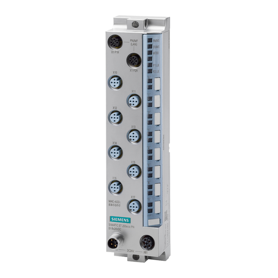
Product overview Properties Article number 6ES7141-6BG00-0BB0 View of the I/O device Figure 2-1 View of the I/O device DI 8x24VDC M12-L 8xM12 I/O device digital inputs DI 8x24VDC M12-L 8xM12 (6ES7141-6BG00-0BB0) Equipment Manual, 02/2022, A5E46570417-AC... - Page 13 Product overview 2.1 Properties Properties The I/O device has the following technical properties: • Using the MultiFieldbus function, it connects the ET 200eco PN M12-L distributed I/O system with one of the following bus protocols: – PROFINET IO – EtherNet/IP –...
- Page 14 Product overview 2.1 Properties See also You can find additional information on the accessories in the ET 200eco PN M12-L distributed I/O system (https://support.industry.siemens.com/cs/ww/en/view/109778292) system manual. I/O device digital inputs DI 8x24VDC M12-L 8xM12 (6ES7141-6BG00-0BB0) Equipment Manual, 02/2022, A5E46570417-AC...
-
Page 15: Operator Controls And Display Elements
Product overview 2.2 Operator controls and display elements Operator controls and display elements The figure below shows the operator controls and display elements of the DI 8x24VDC M12-L 8xM12 I/O device. ① PN/MF (LAN): Sockets for connecting MultiFieldbus ② RN/NS: RUN/network status LED ③... -
Page 16: Wiring
Wiring Terminal and block diagram The figure below shows an example of the pin assignment of signal inputs with 2-wire and 3-wire connection with single and dual assignment of the sockets. * = with set parameter "Dual assignment of the socket" I/O device digital inputs DI 8x24VDC M12-L 8xM12 (6ES7141-6BG00-0BB0) Equipment Manual, 02/2022, A5E46570417-AC... -
Page 17: Pin Assignment
Wiring 3.2 Pin assignment ① Bus interface with integrated 2-port switch X1 P2R MultiFieldbus interface X1 Port 2 ② DI circuit Supply voltage 1L+ (non-switched) ③ Internal supply voltage Ground 1M (non-switched) ④ 2-wire connection (dual assignment of the Load voltage 2L+ (switched) socket) ⑤... - Page 18 Wiring 3.2 Pin assignment Pin assignment of the sockets for digital inputs The table below shows the pin assignment of the 8 sockets for the connection of digital inputs. Table 3- 2 Pin assignment for digital inputs Assignment Front view of the sockets X10 to X17 - sockets for digital inputs X10, X12, X11, X13,...
- Page 19 Wiring 3.2 Pin assignment The following graphic shows the assignment of the input signals to the respective sockets with dual or single assignment. Figure 3-2 Assignment of input signals with dual or single assignment of sockets Pin assignment of the connector for infeed of the supply voltage (M12 L-coded) The table below shows the pin assignment of the M12 L-coded connector for infeed of the supply voltage.
- Page 20 Wiring 3.2 Pin assignment Pin assignment of the socket for loop-through of the supply voltage (M12 L-coded) The table below shows the pin assignment of the M12 L-coded socket for loop-through of the supply voltage. Table 3- 4 Pin assignment of the supply voltage socket Assignment of the Assignment Front view of the...
-
Page 21: Profinet Io
PROFINET IO Parameters/address space 4.1.1 Parameters The table below shows the parameters for the I/O device digital inputs DI 8x24VDC M12-L 8xM12. Table 4- 1 Configurable parameters and their defaults (GSD file) Parameters Value range Default Scope with configuration software, e.g. STEP 7 (TIA Portal) Dual assignment of the socket Disable... -
Page 22: Explanation Of The Parameters
PROFINET IO 4.1 Parameters/address space 4.1.2 Explanation of the parameters Dual assignment of the socket Defines whether dual assignment of the socket is enabled for the respective channel group. The channel groups are defined by the digital inputs of the relevant sockets: •... -
Page 23: Address Space
PROFINET IO 4.1 Parameters/address space Input delay This parameter can be used to suppress signal interference. Changes to the signal are only detected if they are present consistently for longer than the set input delay time. In isochronous mode, the terminal signal is read in at the time T (time for reading the input data). - Page 24 PROFINET IO 4.1 Parameters/address space The following configurations are possible: Table 4- 2 Configuration options Configuration Short designation/ Configuration software, e.g., with STEP 7 (TIA Portal) device name in the Integrated in hardware GSD file in GSD file (device view catalog STEP 7 STEP 7 (TIA Portal) V11 or in the configuration...
- Page 25 PROFINET IO 4.1 Parameters/address space Value status (Quality Information, QI) The value status is always returned with the following configuration options: • DI 8x24VDC QI, • DI 8x24VDC MSI Evaluating the value status An additional byte is occupied in the input address space if you enable the value status for the I/O device.
- Page 26 You can find information on the functionality Module-internal Shared Input/Shared Output (MSI/MSO) in the STEP 7 online help or in the function manual SIMATIC PROFINET with STEP 7 (https://support.industry.siemens.com/cs/ww/en/view/49948856). I/O device digital inputs DI 8x24VDC M12-L 8xM12 (6ES7141-6BG00-0BB0) Equipment Manual, 02/2022, A5E46570417-AC...
-
Page 27: Interrupts/Diagnostics Alarms
PROFINET IO 4.2 Interrupts/diagnostics alarms Interrupts/diagnostics alarms 4.2.1 Status and error displays LED displays The figure below shows the LED displays (status and error displays) of the I/O device DI 8x24VDC M12-L 8xM12. ① RN/NS: RUN/network status LED ② ER/MS: ERROR/module status LED ③... - Page 28 PROFINET IO 4.2 Interrupts/diagnostics alarms Meaning of the LEDs The following tables set out the meaning of the status and error displays. Measures for dealing with diagnostics alarms can be found in the section Diagnostics alarms (Page 30). Behavior of the LEDs RN/NS (RUN/network status), ER/MS (ERROR/module status) and MT/IO (MAINT/IO status) on PROFINET Table 4- 3 Fault display of the LEDs...
- Page 29 PROFINET IO 4.2 Interrupts/diagnostics alarms LEDs Meaning Solution Maintenance Evaluate the maintenance relevant relevant events. The "Node flash test" is running (the P1 LK and P2 LK LEDs of the Flashes Flashes Flashes PROFINET interface are also flashing). Hardware or firmware defec- Replace the ET 200eco PN I/O tive.
-
Page 30: Interrupts
PROFINET IO 4.2 Interrupts/diagnostics alarms 4.2.2 Interrupts The I/O device digital inputs DI 8x24VDC M12-L 8xM12 supports diagnostic and hardware interrupts. Diagnostic interrupt The I/O device generates a diagnostic interrupt on the following events: • Wire break • Internal module fault •... -
Page 31: Alarms
PROFINET IO 4.2 Interrupts/diagnostics alarms 4.2.3 Alarms 4.2.3.1 Diagnostics alarms A diagnostics alarm is output for each diagnostics event. On the I/O device DI 8x24VDC M12-L 8xM12 the LED ER/MS flashes red. You can read out the diagnostics alarms in the diagnostics buffer of the CPU, for example. You can evaluate the error codes with the user program. -
Page 32: Maintenance Events
PROFINET IO 4.2 Interrupts/diagnostics alarms 4.2.3.2 Maintenance events Triggering of a maintenance event The MultiFieldbus interfaces of the ET 200eco PN M12-L support the diagnostics concept and maintenance concept in PROFINET according to the IEC 61158-6-10 standard. The goal is to detect and remove potential problems as soon as possible. -
Page 33: Hardware Interrupts
PROFINET IO 4.2 Interrupts/diagnostics alarms 4.2.3.3 Hardware interrupts During a hardware interrupt, the CPU interrupts processing of the user program and processes the hardware interrupt organization block. For detailed information on the event, refer to the hardware interrupt organization block with the "RALRM"... -
Page 34: Ethernet/Ip
EtherNet/IP Functions/parameters/address space 5.1.1 Supported EtherNet/IP functions Supported functions The table below shows the functions that the module supports with EtherNet/IP. Supported functions Remarks I/O communication with scanner FW 5.1.x or higher Parameter assignment FW 5.1.x or higher Reading diagnostics FW 5.1.x or higher Normative CIP objects FW 5.1.x or higher... -
Page 35: Parameters
EtherNet/IP 5.1 Functions/parameters/address space Supported CIP objects for EtherNet/IP The table below shows the functions that the module supports with EtherNet/IP. Supported CIP object Remarks Identity object FW 5.1.x or higher Assembly object FW 5.1.x or higher Connection Manager object FW 5.1.x or higher TCP/IP Interface object FW 5.1.x or higher... -
Page 36: Explanation Of The Parameters
EtherNet/IP 5.1 Functions/parameters/address space Parameters Value range Default Effective range with configuration software, for example, MFCT Hardware interrupt on rising Disable Channel • Disable edge • Enable Hardware interrupt on falling Disable Channel • Disable edge • Enable * = Short-circuit monitoring of the socket takes place once via Pin 1 (1L+) and Pin 3 (1M). 5.1.3 Explanation of the parameters Dual assignment of the socket... -
Page 37: Update Time Of The I/O Data
EtherNet/IP 5.1 Functions/parameters/address space Input delay This parameter can be used to suppress signal interference. Changes to the signal are only detected if they are present consistently for longer than the set input delay time. For input channels with longer input delays, the read-in time is moved accordingly. This means individual channels can be assigned input delays, if necessary, without having a negative impact on the possible cycle time. -
Page 38: Address Space
EtherNet/IP 5.1 Functions/parameters/address space 5.1.5 Address space The DI 8x24VDC M12-L 8xM12 I/O device can be configured differently; see following table. Depending on the configuration, additional/different addresses are assigned in the process image input. Configuration options of the DI 8x24VDC M12-L 8xM12 I/O device When the I/O device is configured using a GSD file, the configurations are available under different short designations/device names in the device view of MFCT. - Page 39 EtherNet/IP 5.1 Functions/parameters/address space Address space for configuration as 1 x 8-channel DI 8x24VDC The following figure shows the address space allocation for the configuration as 8-channel I/O device digital inputs without value status. Figure 5-1 Address space for configuration as 1 x 8-channel DI 8x24VDC without value status I/O device digital inputs DI 8x24VDC M12-L 8xM12 (6ES7141-6BG00-0BB0) Equipment Manual, 02/2022, A5E46570417-AC...
- Page 40 EtherNet/IP 5.1 Functions/parameters/address space Value status (Quality Information, QI) The value status is always returned with the following configuration options: • DI 8x24VDC QI, • DI 8x24VDC MSI Evaluating the value status An additional byte is occupied in the input address space if you enable the value status for the I/O device.
- Page 41 EtherNet/IP 5.1 Functions/parameters/address space Address space for configuration as 1 x 8-channel DI 8x24VDC MSI With the configuration 1 x 8-channel I/O device (module-internal shared input, MSI), the channels 0 to 7 (incl. value status) of the I/O device are copied into a submodule. Channels 0 to 7 (incl.
- Page 42 5.1 Functions/parameters/address space Reference You can find information about the Module Internal Shared Input/Shared Output (MSI/MSO) functionality in the MultiFieldbus (https://support.industry.siemens.com/cs/ww/en/view/109773209) Function Manual SIMATIC PROFINET with STEP 7 (https://support.industry.siemens.com/cs/ww/en/view/49948856). I/O device digital inputs DI 8x24VDC M12-L 8xM12 (6ES7141-6BG00-0BB0) Equipment Manual, 02/2022, A5E46570417-AC...
-
Page 43: Diagnostics
EtherNet/IP 5.2 Diagnostics Diagnostics 5.2.1 Status and error displays for EtherNet/IP LED displays The figure below shows the LED displays (status and fault displays) of the I/O device DI 8x24VDC M12-L 8xM12. ① RN/NS: RUN/network status LED ② ER/MS: ERROR/module status LED ③... - Page 44 EtherNet/IP 5.2 Diagnostics Behavior of the LEDs RN/NS (RUN/network status), ER/MS (ERROR/module status) and MT/IO (MAINT/IO status) on EtherNet/IP The LEDs display the status with the highest priority if there are different LED states due to overlaid events. (0 = off, 1 = green flashing, 2 = green, 3 = yellow, 4 = red flashing, 5 = red) The following table shows the meaning of the RN/NS, ER/MS LEDs and MT/IO LEDs for EtherNet/IP: Table 5- 3...
- Page 45 EtherNet/IP 5.2 Diagnostics LEDs Meaning Remedy Hardware or firmware defective. You can read out the ser- vice data with MFCT. Flashes Flashes Flashes The "Node flash test" is running (the P1 LK and P2 LK LEDs are also flash- Flashes Flashes Flashes ing).
-
Page 46: Modbus Tcp
Modbus TCP Functions/parameters/address space 6.1.1 Supported Modbus TCP functions Supported functions The table below shows the functions that the module supports with Modbus TCP. Supported functions RegLayoutVer- Remarks sion I/O communication with Modbus client V1.0 FW 5.1.x or higher Free user registers (e.g. for coordination of the redundancy) V1.0 FW 5.1.x or higher Device information... -
Page 47: Parameters
Modbus TCP 6.1 Functions/parameters/address space 6.1.2 Parameters The table below shows the parameters for the I/O device digital inputs DI 8x24VDC M12-L 8xM12. Table 6- 1 Configurable parameters and their defaults (GSD file) Parameters Value range Default Effective range with configuration software, for example, MFCT Dual assignment of the sock- Disable... -
Page 48: Explanation Of The Parameters
Modbus TCP 6.1 Functions/parameters/address space 6.1.3 Explanation of the parameters Dual assignment of the socket Defines whether dual assignment of the socket is enabled for the respective channel group. The channel groups are defined by the digital inputs of the relevant sockets: •... -
Page 49: Update Time Of The I/O Data
Modbus TCP 6.1 Functions/parameters/address space Hardware interrupt on falling edge Specifies whether a hardware interrupt is generated via the data status on a falling edge on the channel. The hardware interrupt information can be read and confirmed via the event interface. - Page 50 Modbus TCP 6.1 Functions/parameters/address space Address space for configuration as 1 x 8-channel DI 8x24VDC The following figure shows the address space allocation for the configuration as 8-channel I/O device digital inputs without value status. Figure 6-1 Address space for configuration as 1 x 8-channel DI 8x24VDC without value status I/O device digital inputs DI 8x24VDC M12-L 8xM12 (6ES7141-6BG00-0BB0) Equipment Manual, 02/2022, A5E46570417-AC...
- Page 51 Modbus TCP 6.1 Functions/parameters/address space Value status (Quality Information, QI) The value status is always returned with the following configuration options: • DI 8x24VDC QI, • DI 8x24VDC MSI Evaluating the value status An additional byte is occupied in the input address space if you enable the value status for the I/O device.
- Page 52 Modbus TCP 6.1 Functions/parameters/address space Address space for configuration as 1 x 8-channel DI 8x24VDC MSI With the configuration 1 x 8-channel I/O device (module-internal shared input, MSI), the channels 0 to 7 (incl. value status) of the I/O device are copied into a submodule. Channels 0 to 7 (incl.
- Page 53 6.1 Functions/parameters/address space Reference You can find information about the Module Internal Shared Input/Shared Output (MSI/MSO) functionality in the MultiFieldbus (https://support.industry.siemens.com/cs/ww/en/view/109773209) Function Manual SIMATIC PROFINET with STEP 7 (https://support.industry.siemens.com/cs/ww/en/view/49948856). I/O device digital inputs DI 8x24VDC M12-L 8xM12 (6ES7141-6BG00-0BB0) Equipment Manual, 02/2022, A5E46570417-AC...
-
Page 54: Diagnostics
Modbus TCP 6.2 Diagnostics Diagnostics 6.2.1 Status and error displays for Modbus TCP LED displays The figure below shows the LED displays (status and fault displays) of the I/O device DI 8x24VDC M12-L 8xM12. ① RN/NS: RUN/network status LED ② ER/MS: ERROR/module status LED ③... - Page 55 Modbus TCP 6.2 Diagnostics Behavior of the LEDs RN/NS (RUN/network status), ER/MS (ERROR/module status) and MT/IO (MAINT/IO status) on modbus TCP The LEDs display the status with the highest priority if there are different LED states due to overlaid events. (0 = off, 1 = green flashing, 2 = green, 3 = yellow, 4 = red flashing, 5 = red) The following table shows the meaning of the RN/NS, ER/MS LEDs and MT/IO LEDs for Modbus TCP: Table 6- 3...
- Page 56 Modbus TCP 6.2 Diagnostics P1 LK and P2 LK LEDs Table 6- 4 Error display of the P1 LK and P2 LK LEDs LEDs Meaning Remedy P1 LK P2 LK There is no Ethernet connection between Check whether the bus cable to the the communications interface of your IO switch/communication partner is inter- device and a communication partner...
- Page 57 Technical specifications of the I/O device digital inputs DI 8x24VDC M12-L 8xM12 The following table shows the technical specifications as of the issue date. You can find a data sheet including daily updated technical specifications on the Internet (https://support.industry.siemens.com/cs/de/en/pv/6ES7141-6BG00-0BB0/td?dl=en). Article number 6ES7141-6BG00-0BB0...
- Page 58 Technical specifications Article number 6ES7141-6BG00-0BB0 Input current Current consumption (rated value) 85 mA; without load from load voltage 1L+ (unswitched voltage) 12 A; Maximum value from load voltage 2L+, max. 12 A; Maximum value Encoder supply Number of outputs 24 V encoder supply Yes;...
- Page 59 Technical specifications Article number 6ES7141-6BG00-0BB0 Interfaces Number of PROFINET interfaces 1. Interface Interface type PROFINET with 100 Mbit/s full duplex (100BASE- Interface types Yes; 2x M12, 4-pin, D-coded • M12 port • Number of ports • integrated switch Protocols • PROFINET IO Device •...
- Page 60 Technical specifications Article number 6ES7141-6BG00-0BB0 EtherNet/IP Services – CIP Implicit Messaging – CIP Explicit Messaging – CIP Safety – Yes; 2x EtherNet/IP Scanner Shared device – Number of scanners with shared device, max. Updating times – 2 ms Requested Packet Interval (RPI) Redundancy mode –...
- Page 61 Technical specifications Article number 6ES7141-6BG00-0BB0 Isochronous mode Equidistance shortest clock pulse 250 µs max. cycle 4 ms Jitter, max. 10 µs Interrupts/diagnostics/status information Alarms Yes; Parameterizable • Diagnostic alarm Yes; Parameterizable • Maintenance interrupt Yes; Parameterizable • Hardware interrupt Diagnoses •...
- Page 62 Technical specifications Article number 6ES7141-6BG00-0BB0 Standards, approvals, certificates Suitable for safety-related tripping of standard Yes; From FS01 modules Highest safety class achievable for safety- related tripping of standard modules PL d • Performance level according to ISO 13849-1 Cat. 3 •...
- Page 63 Dimension drawing Dimension drawing The figure below shows the dimension drawing of the I/O device digital inputs DI 8x24VDC M12-L 8xM12 in front and side views. Figure A-1 Dimension drawing I/O device digital inputs DI 8x24VDC M12-L 8xM12 (6ES7141-6BG00-0BB0) Equipment Manual, 02/2022, A5E46570417-AC...
Need help?
Do you have a question about the SIMATIC ET 200eco PN M12-L and is the answer not in the manual?
Questions and answers