Siemens SIMATIC ET 200eco PN M12-L Equipment Manual
Hide thumbs
Also See for SIMATIC ET 200eco PN M12-L:
- Operating instructions manual (278 pages) ,
- Compact operating instructions (156 pages) ,
- System manual (127 pages)

Related Manuals for Siemens SIMATIC ET 200eco PN M12-L


Summary of Contents for Siemens SIMATIC ET 200eco PN M12-L
- Page 1 Edition 03/2023 Equipment Manual SIMATIC ET 200eco PN M12-L I/O device digital inputs DI 16x24VDC M12-L 8xM12 (6ES7141-6BH00-0BB0) support.industry.siemens.com...
- Page 2 Guide to ET 200eco PN M12-L Product overview SIMATIC Wiring ET 200eco PN I/O device digital inputs DI PROFINET IO 16x24VDC M12-L 8xM12 (6ES7141-6BH00-0BB0) EtherNet/IP Equipment Manual Modbus TCP Technical specifications Dimension drawing Parameter data record 03/2023 A5E46570510-AD...
- Page 3 Note the following: WARNING Siemens products may only be used for the applications described in the catalog and in the relevant technical documentation. If products and components from other manufacturers are used, these must be recommended or approved by Siemens. Proper transport, storage, installation, assembly, commissioning, operation and maintenance are required to ensure that the products operate safely and without any problems.
- Page 4 Preface Purpose of the documentation This equipment manual supplements the ET 200eco PN M12-L Distributed I/O System (https://support.industry.siemens.com/cs/ww/en/view/109778292) system manual. Functions that relate in general to the distributed I/O devices ET 200eco PN M12‑L are described in this system manual. The MultiFieldbus (https://support.industry.siemens.com/cs/ww/en/view/109773209) Function Manual describes general MultiFieldbus functions. This equipment manual describes the specific adaptations for this I/O device.
- Page 5 Siemens' products and solutions undergo continuous development to make them more secure. Siemens strongly recommends that product updates are applied as soon as they are available and that the latest product versions are used. Use of product versions that are no longer supported, and failure to apply the latest updates may increase customers' exposure to cyber threats.
-
Page 6: Table Of Contents
Table of contents Guide to ET 200eco PN M12-L......................Information classes ET 200eco PN M12-L................Basic tools........................MultiFieldbus Configuration Tool (MFCT)................SIMATIC Technical Documentation..................12 Product overview..........................14 Properties ........................14 Operator controls and display elements................16 Wiring..............................17 Terminal and block diagram....................17 Pin assignment......................... - Page 7 Table of contents 6.1.1 Supported Modbus TCP functions..................44 6.1.2 Parameters........................45 6.1.3 Explanation of the parameters..................46 6.1.4 Update time of the I/O data....................47 6.1.5 Address space........................47 Diagnostics........................52 6.2.1 Status and error displays for Modbus TCP................52 Technical specifications........................
-
Page 8: Guide To Et 200Eco Pn M12-L
This arrangement enables you to access the specific content you require. You can download the documentation free of charge from the Internet (https://support.industry.siemens.com/cs/de/en/view/109742718). Basic information The System Manual describes in detail the configuration, installation, wiring and commissioning of the SIMATIC ET 200eco PN M12-L distributed I/O system. -
Page 9: Basic Tools
With the TIA Selection Tool , you can generate a complete order list from your product selection or product configuration. You can find the TIA Selection Tool on the Internet. (https://support.industry.siemens.com/cs/ww/en/view/109767888) SIMATIC Automation Tool You can use the SIMATIC Automation Tool to perform commissioning and maintenance activities on various SIMATIC S7 stations as bulk operations independent of TIA Portal. - Page 10 You can find SIEMENS PRONETA Basic on the Internet: (https://support.industry.siemens.com/cs/ww/en/view/67460624) SIEMENS PRONETA Professional is a licensed product that offers you additional functions. It offers you simple asset management in PROFINET networks and supports operators of automation systems in automatic data collection/acquisition of the components used through various functions: •...
-
Page 11: Multifieldbus Configuration Tool (Mfct)
MultiFieldbus- and DALI-devices. In addition, the MFCT offers convenient options for mass firmware updates of ET 200 devices with MultiFieldbus- support and reading service data for many other Siemens devices. Functional scope of the MFCT • MultiFieldbus configuration:... -
Page 12: Simatic Technical Documentation
Online Support: Industry Online Support International https://support.industry.siemens.com/cs/ww/en/view/109742705 Watch this short video to find out where you can find the overview directly in Siemens Industry Online Support and how to use Siemens Industry Online Support on your mobile device: Quick introduction to the technical documentation of automation products per video ( https://support.industry.siemens.com/cs/us/en/view/109780491... - Page 13 Solutions are shown in interplay with multiple components in the system - separated from the focus on individual products. You can find the application examples on the Internet. (https://support.industry.siemens.com/cs/ww/en/ps/ae) I/O device digital inputs DI 16x24VDC M12-L 8xM12 (6ES7141-6BH00-0BB0) Equipment Manual, 03/2023, A5E46570510-AD...
-
Page 14: Product Overview
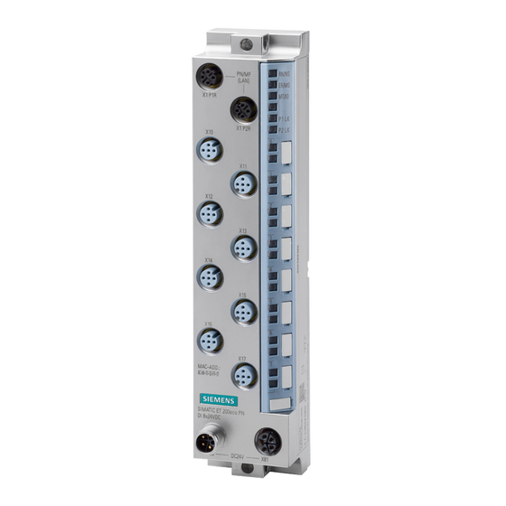
Product overview Properties Article number 6ES7141-6BH00-0BB0 View of the I/O device Figure 2-1 View of the I/O device DI 16x24VDC M12-L 8xM12 I/O device digital inputs DI 16x24VDC M12-L 8xM12 (6ES7141-6BH00-0BB0) Equipment Manual, 03/2023, A5E46570510-AD... - Page 15 • Connectors and cables • M12 sealing cap See also You can find additional information on the accessories in the ET 200eco PN M12-L distributed I/O system (https://support.industry.siemens.com/cs/ww/en/view/109778292) system manual. I/O device digital inputs DI 16x24VDC M12-L 8xM12 (6ES7141-6BH00-0BB0) Equipment Manual, 03/2023, A5E46570510-AD...
-
Page 16: Operator Controls And Display Elements
Product overview 2.2 Operator controls and display elements Operator controls and display elements The figure below shows the operator controls and display elements of the DI 16x24VDC M12‑L 8xM12 I/O device. PN/MF RN/NS (LAN) ER/MS MT/IO X1 P1R P1 LK X1 P2R P2 LK MAC-ADD.;... -
Page 17: Wiring
Wiring Terminal and block diagram The figure below shows an example of the connections and components of the I/O device. ① Bus interface with integrated X1 P1R MultiFieldbus interface X1 RN/NS RUN/network status LED 2-port switch port 1 ② DI circuit X1 P2R MultiFieldbus interface X1 ER/MS ERROR/module status LED port 2 ③... - Page 18 Wiring 3.1 Terminal and block diagram Terminal circuit diagram The figure below shows an example of the pin assignment of signal inputs with 2-wire and 3-wire connection with single and dual assignment of the sockets. ① 2-wire connection (dual Supply voltage 1L+ (non- Load voltage 2L+ (switched) assignment of the socket) switched)
-
Page 19: Pin Assignment
Wiring 3.2 Pin assignment Pin assignment Pin assignment MultiFieldbus connector The following table shows the pin assignment of the MultiFieldbus connector. Table 3-1 Pin assignment of the MultiFieldbus connector, port 1 and 2 Assignment of the core Assignment Front view of the connectors color of the PROFINET cable Assignment X1 P1R... - Page 20 Wiring 3.2 Pin assignment Assignment Front view of the sockets X10 to X17 - sockets for digital inputs X10, X12, X11, X13, X14, X16 X15, X17 Input signal DI : Connector X10 Input signal DI : Connector X11 Input signal DI : Connector X12 Input signal DI : Connector X13...
- Page 21 Wiring 3.2 Pin assignment Pin assignment of the socket for loop-through of the supply voltage (M12 L-coded) The table below shows the pin assignment of the M12 L-coded socket for loop-through of the supply voltage. Table 3-4 Pin assignment of the supply voltage socket Assignment of the Assignment Front view of the sock...
-
Page 22: Profinet Io
PROFINET IO Parameters/address space 4.1.1 Parameters The table below shows the parameters for the I/O device digital inputs DI 16x24VDC M12‑L 8xM12. Table 4-1 Configurable parameters and their defaults (GSD file) Parameters Value range Default Scope with configura tion software, e.g. STEP 7 (TIA Portal) Diagnostics: Low voltage 1L+ •... -
Page 23: Explanation Of The Parameters
PROFINET IO 4.1 Parameters/address space 4.1.2 Explanation of the parameters Diagnostics: Low voltage 1L+ Enabling of the diagnostics for insufficient supply voltage 1L+. Diagnostics: Low voltage 1L+ triggers the "Undervoltage" maintenance event. You can find more information in section Maintenance events (Page 31). Diagnostics: Short-circuit Enabling of diagnostics for short-circuit to ground at transducer supply Diagnostics: Wire break detection and alarm... -
Page 24: Address Space
PROFINET IO 4.1 Parameters/address space Hardware interrupt on falling edge Specifies whether a hardware interrupt is generated for a falling edge on the channel. A hardware interrupt is only generated for the channel when there is a fault-free signal (value status/QI = 1). - Page 25 PROFINET IO 4.1 Parameters/address space Value status (Quality Information, QI) The value status is always returned with the following configuration options: • DI 16x24VDC QI • DI 16x24VDC MSI Evaluating the value status An additional two bytes are occupied in the input address space if you enable the value status for the I/O device.
- Page 26 PROFINET IO 4.1 Parameters/address space Address space for configuration as 1 x 16-channel DI 16x24VDC MSI With the configuration 1 x 16-channel I/O device (module-internal shared input, MSI), the channels 0 to 15 (incl. value status) of the I/O device are copied into a submodule. Channels 0 to 15 (incl.
-
Page 27: Interrupts/Diagnostics Alarms
4.2 Interrupts/diagnostics alarms Reference You can find information on the functionality Module-internal Shared Input/Shared Output (MSI/MSO) in the STEP 7 online help or in the function manual SIMATIC PROFINET with STEP 7 (https://support.industry.siemens.com/cs/ww/en/view/49948856). Interrupts/diagnostics alarms 4.2.1 Status and error displays LED displays The figure below shows the LED displays (status and error displays) of the I/O device DI 16x24VDC M12-L 8xM12. - Page 28 PROFINET IO 4.2 Interrupts/diagnostics alarms Meaning of the LEDs The following tables set out the meaning of the status and error displays. Measures for dealing with diagnostics alarms can be found in the section Diagnostics alarms (Page 30-31). Behavior of the LEDs RN/NS (RUN/network status), ER/MS (ERROR/module status) and MT/IO (MAINT/IO status) on PROFINET Table 4-3 Error display of the LEDs LEDs...
- Page 29 PROFINET IO 4.2 Interrupts/diagnostics alarms P1 LK and P2 LK LEDs Table 4-4 Error display of the P1 LK and P2 LK LEDs LEDs Meaning Remedy P1 LK P2 LK There is no Ethernet connection between Check whether the bus cable to the the communications interface of your IO switch/communication partner is interrup...
-
Page 30: Interrupts
PROFINET IO 4.2 Interrupts/diagnostics alarms 4.2.2 Interrupts The I/O device digital inputs DI 16x24VDC M12-L 8xM12 supports diagnostic and hardware interrupts. Diagnostic interrupt The I/O device generates a diagnostic interrupt on the following events: • Wire break • Internal module fault •... -
Page 31: Alarms
PROFINET IO 4.2 Interrupts/diagnostics alarms 4.2.3 Alarms 4.2.3.1 Diagnostics alarms A diagnostics alarm is output for each diagnostics event. On the I/O device DI 16x24VDC M12‑L 8xM12 the LED ER/MS flashes red. You can read out the diagnostics alarms in the diagnostics buffer of the CPU, for example. You can evaluate the error codes with the user program. -
Page 32: Maintenance Events
PROFINET IO 4.2 Interrupts/diagnostics alarms 4.2.3.2 Maintenance events Triggering of a maintenance event The MultiFieldbus interfaces of the ET 200eco PN M12-L support the diagnostics concept and maintenance concept in PROFINET according to the IEC 61158-6-10 standard. The goal is to detect and remove potential problems as soon as possible. -
Page 33: Ethernet/Ip
EtherNet/IP Functions/parameters/address space 5.1.1 Supported EtherNet/IP functions Supported functions The table below shows the functions that the I/O device supports with EtherNet/IP. Supported functions Remarks I/O communication with scanner FW 5.1.x or higher Parameter assignment FW 5.1.x or higher Reading diagnostics FW 5.1.x or higher Normative CIP objects FW 5.1.x or higher... -
Page 34: Parameters
EtherNet/IP 5.1 Functions/parameters/address space Supported CIP objects for EtherNet/IP The table below shows the CIP objects that the I/O device supports with EtherNet/IP. Supported CIP objects Remarks Identity object FW 5.1.x or higher Assembly object FW 5.1.x or higher Connection Manager object FW 5.1.x or higher TCP/IP Interface object FW 5.1.x or higher... -
Page 35: Explanation Of The Parameters
EtherNet/IP 5.1 Functions/parameters/address space 5.1.3 Explanation of the parameters Diagnostics: Low voltage 1L+ Enabling of the diagnostics for insufficient supply voltage 1L+. Diagnostics: Short-circuit Enabling of diagnostics for short-circuit to ground at transducer supply Diagnostics: Wire break detection and alarm Activates wire break detection and enabling of diagnostics for the digital input in case of an interruption of the cable between the encoder and I/O device. -
Page 36: Update Time Of The I/O Data
EtherNet/IP 5.1 Functions/parameters/address space 5.1.4 Update time of the I/O data You can estimate the typical update time for an I/O cycle as follows: RPI timer (settable from 2 to 20 ms ± 10 %) default 10 ms + I/O processing (typically 1.4 ms, ± 1 ms jitter due to free-running cycles) + EM conversion (dependent on cycle time and parameter assignment of the module) If necessary, you must take into account other influences caused by the EIP scanner and network components by adding them. - Page 37 EtherNet/IP 5.1 Functions/parameters/address space Address space for configuration as 1 x 16-channel DI 16x24VDC The following figure shows the address space allocation for the configuration as 16-channel I/O device digital inputs without value status. Figure 5-1 Address space for configuration as 1 x 16-channel DI 16x24VDC without value status Value status (Quality Information, QI) The value status is always returned with the following configuration options: •...
- Page 38 EtherNet/IP 5.1 Functions/parameters/address space Address space for configuration as 1 x 16-channel DI 16x24VDC QI The following figure shows the address space allocation for the configuration as 16-channel I/O device digital inputs with value status. The addresses of the channels are derived from the start address.
- Page 39 EtherNet/IP 5.1 Functions/parameters/address space Address space for configuration as 1 x 16-channel DI 16x24VDC MSI With the configuration 1 x 16-channel I/O device (module-internal shared input, MSI), the channels 0 to 15 (incl. value status) of the I/O device are copied into a submodule. Channels 0 to 15 (incl.
- Page 40 Figure 5-3 Address space for configuration as 1 x 16-channel DI 16x24VDC MSI with value status Reference You can find information about the Module Internal Shared Input/Shared Output (MSI/MSO) functionality in the MultiFieldbus (https://support.industry.siemens.com/cs/ww/en/view/109773209) Function Manual SIMATIC PROFINET with STEP 7 (https://support.industry.siemens.com/cs/ww/en/view/49948856). I/O device digital inputs DI 16x24VDC M12-L 8xM12 (6ES7141-6BH00-0BB0) Equipment Manual, 03/2023, A5E46570510-AD...
-
Page 41: Diagnostics
EtherNet/IP 5.2 Diagnostics Diagnostics 5.2.1 Status and error displays for EtherNet/IP LED displays The figure below shows the LED displays (status and fault displays) of the I/O device DI 16x24VDC M12-L 8xM12. PN/MF RN/NS (LAN) ER/MS MT/IO X1 P1R P1 LK X1 P2R P2 LK MAC-ADD.;... - Page 42 EtherNet/IP 5.2 Diagnostics Behavior of the LEDs RN/NS (RUN/network status), ER/MS (ERROR/module status) and MT/IO (MAINT/IO status) on EtherNet/IP The LEDs display the status with the highest priority if there are different LED states due to overlaid events. (0 = off, 1 = green flashing, 2 = green, 3 = yellow, 4 = red flashing, 5 = red) The following table shows the meaning of the RN/NS, ER/MS LEDs and MT/IO LEDs for EtherNet/IP: Table 5-3 Error display of the LEDs...
- Page 43 EtherNet/IP 5.2 Diagnostics LEDs Meaning Remedy Test of LEDs during startup: The three LEDs light up simultaneously for Flashes Flashes Flashes approximately 0.25 s in red. Then for approximately 0.25 s in green. Hardware or firmware defective. You can read out the service data with MFCT.
-
Page 44: Modbus Tcp
Modbus TCP Functions/parameters/address space 6.1.1 Supported Modbus TCP functions Supported functions The table below shows the functions that the I/O device supports with Modbus TCP. Supported functions RegLayoutVersion Remarks I/O communication with Modbus client V1.0 FW 5.1.x or higher Free user registers (e.g. for coordination of the redundancy) V1.0 FW 5.1.x or higher Device information... -
Page 45: Parameters
Modbus TCP 6.1 Functions/parameters/address space 6.1.2 Parameters The table below shows the parameters for the I/O device digital inputs DI 16x24VDC M12‑L 8xM12. Table 6-1 Configurable parameters and their defaults (GSD file) Parameters Value range Default Effective range with configuration soft ware, for example, MFCT Diagnostics: Low voltage 1L+ •... -
Page 46: Explanation Of The Parameters
Modbus TCP 6.1 Functions/parameters/address space 6.1.3 Explanation of the parameters Diagnostics: Low voltage 1L+ Enabling of the diagnostics for insufficient supply voltage 1L+. Diagnostics: Short-circuit Enabling of diagnostics for short-circuit to ground at transducer supply Diagnostics: Wire break detection and alarm Activates wire break detection and enabling of diagnostics for the digital input in case of an interruption of the cable between the encoder and I/O device. -
Page 47: Update Time Of The I/O Data
Modbus TCP 6.1 Functions/parameters/address space 6.1.4 Update time of the I/O data You can estimate the typical update time for an I/O cycle as follows: Update time (can be set starting at 2 ms) + I/O processing (typically 1.4 ms, +/- 1 ms jitter due to free-running cycles) + EM conversion (dependent on cycle time and parameter assignment of the module) If necessary, you must take into account other influences caused by the MTCP client and network components by adding them. - Page 48 Modbus TCP 6.1 Functions/parameters/address space Address space for configuration as 1 x 16-channel DI 16x24VDC The following figure shows the address space allocation for the configuration as 16-channel I/O device digital inputs without value status. Figure 6-1 Address space for configuration as 1 x 16-channel DI 16x24VDC without value status Value status (Quality Information, QI) The value status is always returned with the following configuration options: •...
- Page 49 Modbus TCP 6.1 Functions/parameters/address space Address space for configuration as 1 x 16-channel DI 16x24VDC QI The following figure shows the address space allocation for the configuration as 16-channel I/O device digital inputs with value status. The addresses of the channels are derived from the start address.
- Page 50 Modbus TCP 6.1 Functions/parameters/address space Address space for configuration as 1 x 16-channel DI 16x24VDC MSI With the configuration 1 x 16-channel I/O device (module-internal shared input, MSI), the channels 0 to 15 (incl. value status) of the I/O device are copied into a submodule. Channels 0 to 15 (incl.
- Page 51 Figure 6-3 Address space for configuration as 1 x 16-channel DI 16x24VDC MSI with value status Reference You can find information about the Module Internal Shared Input/Shared Output (MSI/MSO) functionality in the MultiFieldbus (https://support.industry.siemens.com/cs/ww/en/view/109773209) Function Manual SIMATIC PROFINET with STEP 7 (https://support.industry.siemens.com/cs/ww/en/view/49948856). I/O device digital inputs DI 16x24VDC M12-L 8xM12 (6ES7141-6BH00-0BB0) Equipment Manual, 03/2023, A5E46570510-AD...
-
Page 52: Diagnostics
Modbus TCP 6.2 Diagnostics Diagnostics 6.2.1 Status and error displays for Modbus TCP LED displays The figure below shows the LED displays (status and fault displays) of the I/O device DI 16x24VDC M12-L 8xM12. PN/MF RN/NS (LAN) ER/MS MT/IO X1 P1R P1 LK X1 P2R P2 LK... - Page 53 Modbus TCP 6.2 Diagnostics Behavior of the LEDs RN/NS (RUN/network status), ER/MS (ERROR/module status) and MT/IO (MAINT/IO status) on modbus TCP The LEDs display the status with the highest priority if there are different LED states due to overlaid events. (0 = off, 1 = green flashing, 2 = green, 3 = yellow, 4 = red flashing, 5 = red) The following table shows the meaning of the RN/NS, ER/MS LEDs and MT/IO LEDs for Modbus TCP: Table 6-3 Error display of the LEDs...
- Page 54 Modbus TCP 6.2 Diagnostics PWR LED Table 6-4 Status display of the PWR LED PWR LED Meaning Load voltage 2L+ is missing or too low Load voltage 2L+ present P1 LK and P2 LK LEDs Table 6-5 Error display of the P1 LK and P2 LK LEDs LEDs Meaning Remedy...
-
Page 55: Technical Specifications
Technical specifications of the I/O device digital inputs DI 16x24VDC M12-L 8xM12 The following table shows the technical specifications as of the issue date. You can find a data sheet including daily updated technical specifications on the Internet (https://support.industry.siemens.com/cs/de/en/pv/6ES7141-6BH00-0BB0/td?dl=en). Article number 6ES7141-6BH00-0BB0 General information ... - Page 56 Technical specifications Article number 6ES7141-6BH00-0BB0 Input current Current consumption (rated value) 90 mA; without load from load voltage 1L+ (unswitched voltage) 12 A; Maximum value from load voltage 2L+, max. 12 A; Maximum value Encoder supply Number of outputs 24 V encoder supply ...
- Page 57 Technical specifications Article number 6ES7141-6BH00-0BB0 Encoder Connectable encoders • 2-wire sensor permissible quiescent current (2-wire 1.5 mA – sensor), max. Interfaces Number of PROFINET interfaces 1. Interface Interface type PROFINET with 100 Mbit/s full duplex (100BASE-TX) Interface types ...
- Page 58 Technical specifications Article number 6ES7141-6BH00-0BB0 EtherNet/IP Services – CIP Implicit Messaging CIP Explicit Messaging – – CIP Safety – Shared device Yes; 2x EtherNet/IP Scanner – Number of scanners with shared device, max. Updating times – Requested Packet Interval (RPI) 2 ms Redundancy mode ...
- Page 59 Technical specifications Article number 6ES7141-6BH00-0BB0 Isochronous mode Equidistance shortest clock pulse 250 µs max. cycle 4 ms Jitter, max. 10 µs Interrupts/diagnostics/status information Alarms • Diagnostic alarm Yes; Parameterizable • Maintenance interrupt Yes; Parameterizable • Hardware interrupt Yes; Parameterizable Diagnoses ...
- Page 60 PL d 13849-1 • Category according to ISO 13849-1 Cat. 3 SIL acc. to IEC 62061 SIL 2 • • remark on safety-oriented shutdown https://sup port.industry.siemens.com/cs/de/en/view/39198 Ambient conditions Ambient temperature during operation • min. -40 °C • max. 60 °C Altitude during operation relating to sea level ...
-
Page 61: A Dimension Drawing
Dimension drawing Dimension drawing The figure below shows the dimension drawing of the I/O device digital inputs DI 16x24VDC M12‑L 8xM12 in front and side views. Figure A-1 Dimension drawing I/O device digital inputs DI 16x24VDC M12-L 8xM12 (6ES7141-6BH00-0BB0) Equipment Manual, 03/2023, A5E46570510-AD... -
Page 62: Parameter Data Record
Parameter data record Dependencies for the configuration When configuring the I/O device, the parameter settings are independent of each other. Structure of data record 128 for I/O device parameter assignment With data record 128, you can reconfigure the I/O device in your user program, regardless of your programming. - Page 63 Parameter data record B.2 Structure of data record 128 for I/O device parameter assignment Structure of data record 128 The following figure shows the structure of data record 128 when configured as 1 x 16-channel I/O device. Figure B-1 Structure of data record 128 Header information The figure below shows the structure of the header information.
- Page 64 Parameter data record B.2 Structure of data record 128 for I/O device parameter assignment Device header information The figure below shows the structure of the device header information. Figure B-3 Device header information Device parameter block The figure below shows the structure of the device parameter block. Figure B-4 Device parameter block Channel header information The figure below shows the structure of the channel header information.
- Page 65 Parameter data record B.2 Structure of data record 128 for I/O device parameter assignment Parameters The following figure shows the structure of the parameters for a channel. You can activate a parameter by setting the corresponding bit to "1". * x = 7 + (channel number * 3); channel number = 0 to 15 Figure B-6 Structure of byte x to x + 3 I/O device digital inputs DI 16x24VDC M12-L 8xM12 (6ES7141-6BH00-0BB0) Equipment Manual, 03/2023, A5E46570510-AD...
-
Page 66: Error Transferring The Data Record
Parameter data record B.3 Error transferring the data record Error transferring the data record Error transferring the data record The I/O device checks the values of the transferred data record. Only if the values were transferred without errors does the I/O device apply the values from the data record. The "WRREC"...
Need help?
Do you have a question about the SIMATIC ET 200eco PN M12-L and is the answer not in the manual?
Questions and answers